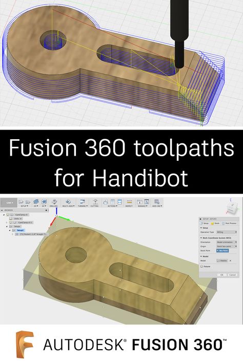
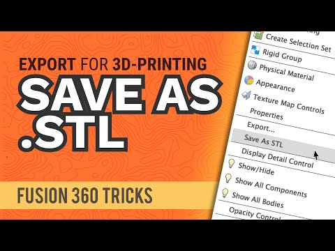
Fusion 360 export for 3d printing
How to 3D Print from Fusion 360
Once a Fusion 360 model is finished, it is time to get it 3D printed. However, the finished 3D model cannot print as-is. A 3D printer (or CNC Machine) needs a toolpath or “instructions” to create the model. Instructions are typically in the form of a G-code (.gcode) file. A 3D Printer’s “slicer” must be used to convert the STL file to G-code. Here are three ways to get your 3D model from Fusion 360 and retrieve G-code.
Save As Mesh
Saving an STL (Standard Tessellation Language) file from Fusion 360 is one of the easiest ways to transfer models from Fusion 360 to a 3D printing slicer. This format uses a series of linked triangles to recreate the surface geometry of the 3D model. Use STL files because they are small in size and easy to transfer to 3D machines and software. STL files can also be uploaded and shared with others via online sites like Thangs and Thingiverse.
Exporting STL from Fusion 360
In Fusion 360, right-click on the root (top-level) component, a component, or a 3D body in the Fusion 360 Browser.
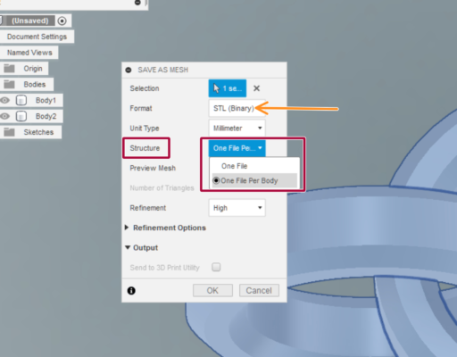
Then, select “Save as Mesh” from the right-click menu. This opens the Save as Mesh Fusion 360 dialog, where we can define the export settings.
3D Print from Fusion 360 using the Save as Mesh selection.Format: We recommend 3MF files over STL files because they include units of measure and some additional metadata.
The Binary option is recommended if you prefer STL files, as it creates a smaller file that is easier to use, share, and store. Both Binary and ASCII will use the same number of triangles and quality, so the smaller file is preferable.
3D Printing: STL files are unitless, so it’s critical to know what unit of measurement the Slicer of software program will expect. See Why is STL 10 times larger than expected.
Structure: If you are printing a model which is already arranged per the print, then the structure should be set to one file. If the model will be arranged as individual parts, then One File per Body will save each body as an individual STL, saving some time by creating multiple files.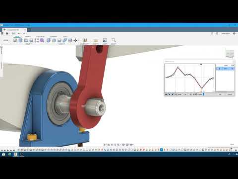
Refinement: If the model contains organic shapes and many curves, then a higher refinement may be required, which will increase the number of triangles saved in the STL. This gives the STL higher resolution but increases the file size.
After defining the settings, select OK to save the mesh file.
Importing STL to a Slicer Software
Many 3D printing companies have software that they recommend when using their 3D printers, such as Cura or Prusa Slicer. In addition, slicers often include templates for common makes and models of 3D printers.
After opening your chosen Slicer, click on the import button (or go to File > Import) and select the STL file from your computer.
Select Slice – note that some slicers automatically do this.
Then save the G-code to your computer or an SD card, depending on your printer’s setup.
Send to Print UtilityIf you would like to 3D print immediately – it is possible to skip the STL export by sending it straight to your chosen slicer.
Select Tools in the toolbar (of the Design Workspace), select Make, then 3D Print. The 3D Print feature will open the same dialog as Save as Mesh.
Check the “Send to 3D Print Utility” in the 3D Print/Save as Mesh dialog. Note that the first time you will be required to select the Application from your computer’s folders.
Once you select OK, Fusion 360 will open the Slicer with the part in the print bed. Double-check that your settings are correct before slicing and saving the G-code.
Send to 3D Print Utility allows you to 3D Print Fusion 360 files using your chosen slicer.Slice Directly in Fusion 360Fusion 360 is a CAD/CAM package that helps you quickly go from design to manufacturing. It’s no surprise that they also allow users to set up additive manufacturing files for 3D printing directly in Fusion 360.
This workflow allows users to get the G-code file without the use of external slicers.
Start by switching to the Manufacture workspace.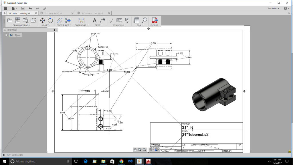 Select the workspaces dropdown in the upper-left, followed by selecting Manufacture.
Select the Additive tab in the toolbar. Then, select the Setup feature, which opens the Setup dialog.
Fusion 360’s Manufacture workspace includes additive functionality to 3D Print from Fusion 360.Machine: Select the 3D printer to be used.
Print Settings: Fusion 360 offers preset settings for each printer. If you don’t find your machine (3D Printer) you can create a custom machine.
Setup: For Operation Type select Additive.
Arrangement: Automatic should be checked.
Model: Select the bodies that are going to be 3D printed.
Select OK.
A new setup has then been created. Right-click on the Additive Toolpath and click generate. There will be a bit of loading, and then you will be able to see how the model is being sliced by selecting Simulate Additive Toolpath.
After defining your print settings, select “Post Process,” then Post. This will allow you to save the G-code to your computer.
Here is an in-depth step-by-step tutorial on Slicing directly in Fusion 360: https://www.youtube.com/watch?v=E6hFaC6dDlM
Save as Mesh (STL) Summary
STL files are the most common file for 3D printing due to their file size and wide acceptance from 3D printer slicers. STL files are small in size and a storage-friendly way to transfer models between different users.
In Fusion 360, sending your model to 3D Print Utility is a quick way to send the 3D model to a slicer without the need to export an STL file. This streamlines the workflow and prevents clutter in your computer storage.
Using Fusion 360’s built-in slicer is a great way to maximize efficiency, allowing you to automatically update toolpaths after making critical design updates.
How to Export STL Files For Best 3D Print Quality - Fusion3
EXPORTING STL FILES FOR BEST 3D PRINTING QUALITY
UNDERSTANDING THE STL FORMAT
A traditional CAD (computer aided design file) uses a series of coordinates and formulas to represent the shape of your 3D object.
However, the .STL format is a bit different. It uses a series of triangles to generate a ‘mesh’ of the surface of your 3D part.
.STL can perfectly replicate a 3D model made up of flat surfaces.
If your model is made up of curves, the .STL file is only making an approximation of your object. This is why the quality of the amount of detail in your exported file is important for the quality of your 3D print.
Two concentric circles, representing a CAD model of a doughnut shape, and a series of triangles approximating the doughnut, representing how STL modeling works. (Source: Wikipedia)
STL file in Fusion3 REACTOR showing too few curves when exported. Note how the rounded surface shows as a series of rectangular bevels.
EXPORTING YOUR CAD FILE WITH TOO FEW POLYGONS
If you export the file with too few polygons, the model will have visible flaws on its surface when printed.
This will most likely appear either as triangles on a rounded surface or rectangular bevels on a curved
EXPORTING YOUR CAD FILE WITH TOO MANY POLYGONS
The reaction by most people is to export the file with as many polygons as possible.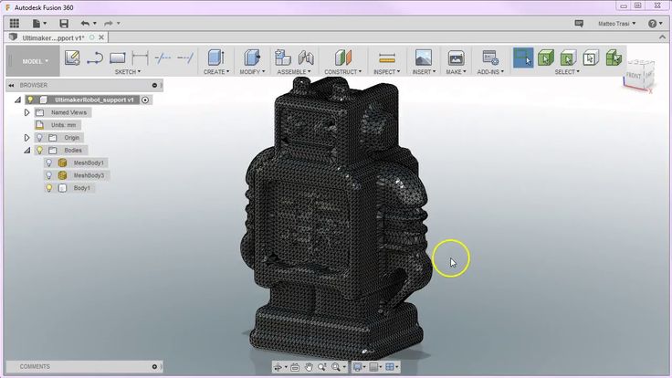 This is also not recommended.
The FDM 3D printing process likely cannot recreate this level of detail. The larger file size and details may cause the slicer software to either:
- Work much more slowly or freeze
- Cause errors for either the printer or software as it attempts to handle levels of detail beyond its capability.
EXPORTING YOUR CAD FILE WITH THE RIGHT AMOUNT OF POLYGONS
As with Goldilocks and the three bears, there is a “just right” level of detail for 3D printing.
This amount of detail provides an amount of polygons sufficient for a 3D printer of the F410’s caliber to be able to create the part in high detail, but not overwhelm the printer’s software.
As shown in the image on the right, rounded shapes appear smooth with a minimum of faceting.
In each of the sections below, we at Fusion3 provide you with a compilation of optimized settings for exporting .STL files with each of the major CAD programs.
.STL file in Fusion3 REACTOR showing sufficient number of polygons to render the curve without overwhelming the software. The rounded surface now appears smooth.
EXPORTING STL FILES FROM SOLIDWORKS FOR BEST 3D PRINTING QUALITY
Most Fusion3 customers use SolidWorks. In the past, SolidWorks’ STL export filter using the “FINE” preset would generate excellent output. However, recently (as of January, 2021), we have found the level of detail to still be inadequate and below the level of detail our 3D printers are capable of.
Here are our recommended settings for exporting an STL file from SolidWorks for 3D printing on a Fusion3 3D printer (and accompanying screen shot):
File Format: STL
Output as:
a. ASCII
b. Unit: Millimeters
Resolution:
a. Custom
b. Deviation: Tolerance 0.09584862mm
c. Angle 3.500 deg
d. Show STL info before saving
e. Define Maximum Facet Size (unchecked)
f. Preview Before Saviing File (unchecked)
Do no translate STL output data to positive space: (unchecked)
Save all components of an assembly in a single file: (unchecked)
.STL file in Fusion3 REACTOR showing sufficient number of polygons to render the curve without overwhelming the software. The rounded surface now appears smooth.
EXPORTING STL FILES FROM AUTODESK INVENTOR FOR BEST 3D PRINTING QUALITY
- Before finalizing your export, select the Options tab.
- Select “High” resolution (faceting) for your model (High, Medium, Low and Custom) and check that your units are correct. The “High” setting will produce a large file size. Autodesk Inventor allows you to save both individual parts and assemblies in STL format, at all design levels.
- Check your modifiers have been applied before exporting:
Tools > Rebuild All (this ensures that the design data contains recent changes, and that it is not corrupt)
File > Save Copy As > STL (.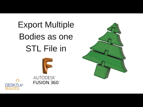 stl)
stl)
Select High and click OKNote: To change the values associated with each of the resolution settings (High/Medium/Low) you need to edit the Windows registry.
Select IPro > Print > 3D Print Preview - Select Options and choose desired resolution and click OK.
- Within the preview window, select Save Copy As or Send to 3D Print Service
- Save As type to STL File (*.stl)
EXPORTING STL FILES FROM AUTODESK FUSION360 FOR BEST 3D PRINTING QUALITY
Step 1.
Right click on a body in the workspace browser.
Select the “Save As STL” Command.
Step 2.
Apply your settings to the body per the settings below.
Format: Binary
Structure: One File
Preview Mesh: Checked
Number of Triangles: (Calculated)
Refinement Options: High
Surface Deviation: .004479mm
Normal Deviation: 10.00
Maximum Edge Length: 89.58237mm
Aspect Ratio: 21.50
EXPORTING STL FILES FROM ONSHAPE (PTC) FOR BEST 3D PRINTING QUALITY
STL Format: Binary
Angular Deviation: 1 Degree
Chordal Tolerance: 0. 1mm (0.004″)
Minimum Facet Width: 0.1mm (0.004″)
EXPORTING STL FILES FROM NX (SIEMENS) FOR BEST 3D PRINTING QUALITY
Output File Type: Binary
Chordal Tolerance: 0.1mm (0.004″)
Angular Tolerance: 1 degree
EXPORTING STL FILES FROM CREO (PTC) FOR BEST 3D PRINTING QUALITY
Creo has a parameter called ‘Angle Control’ that doe not adjust the maximum angular deviation in degrees. Instead, this is a measure of angular deviation beyond the radius that would be created by the ‘Chord height’ (chordal tolerance) parameter.
The ‘Angle control’ parameter value can range from 0.0 to 1.0.
Here are a set of settings we suggest as a starting point:
STL Format: Binary
Chord height: 0.1 mm (0.004″)
Angle Control: 0.25
Maximum Edge Length: Default
Aspect Ratio: Default
CLICK TO REQUEST SAMPLE
Autodesk Fusion 360 Export STL Files
With Autodesk Fusion 360, you can easily export your 3D model STL files and prepare them for slicing, especially after reading this handy guide!
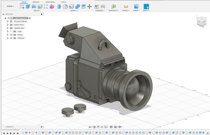
Fusion 360 is an incredibly smart and user-friendly computer-aided design (CAD) and computer-aided manufacturing (CAM) program that streamlines and combines the functionality of traditionally separate programs into one application.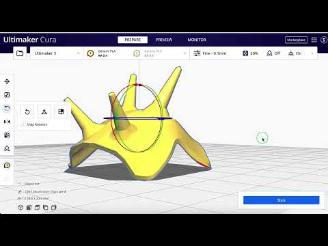
You have bought a 3D printer for your home or business and now you are faced with the task of exporting files to STL format - the most convenient format for 3D printing
Fusion 360 provides an intuitive and convenient environment for complex 2D and 3D projects, as well as tools to analyze and prepare these designs for production or rapid prototyping, including access to the Autodesk 360 cloud. Fusion 360 includes easy-to-use tools for preparing models for 3D printing, making it a great companion for anyone using 3D printing for the manifestation of digital projects, whether for rapid prototyping or just for fun. One such tool is the ability to create custom 3D model meshes and export them to STL files for slicing. nine0003
There are several ways to export 3D designs as STL mesh files in Fusion 360. These methods depend on whether you want to export single components or solids, an entire model, or multiple solids at once.
Export Entire Design
If you want to export the entire design, including all of its bodies and components, you can do so using the Model Browser tree on the left side of the screen. Right-click on the top branch of the tree and select "Save As STL" from the drop-down menu that appears. nine0003
After selecting this option, a small panel will appear on the right side of the screen, in which you can adjust the grid settings. You can also toggle the option to send the file directly to a 3D printing utility such as Cura, Meshmixer, or PreForm.
When prototyping on a 3D printer, we often use Fusion 360 to correct and prepare models for 3D printing.
Exporting Single Components or Solids
To export a single component or solid, simply right-click on the component and select "Save As STL" from the drop-down menu. This action will open the same panel where you can adjust the grid settings. In this window, you can also change the selection of the component or body. nine0003
Alternatively, you can select "3D Print" from the "Make" menu in the toolbar at the top of the screen to open the same panel. From here you can select the component or body you want to export.
Export multiple bodies to a single STL file
If you want to export multiple bodies as a single STL mesh file, you can do so by creating a single component containing all the bodies you want to include.
To do this, first create a new component by clicking "New Component" from the "Create" menu in the toolbar. A panel will open on the right side of the screen, prompting you to select one or more solids from the design. Make sure the "From Bodies" option is enabled, select only one body, and then select "OK". nine0003
After creating a new component, it will appear at the bottom of the browser tree on the left. To add an additional body to this component, simply find the bodies in the tree and drag them to the new component branch in the tree.
You can then right-click on that component and select "Save as STL" from the drop-down menu to open the "Save as STL" panel. In the panel, you will now see the "Structure" option to create one file for the entire component or create a separate file for each body.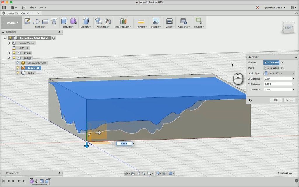 Make sure "One File" is selected and you should be good to go. nine0003
Engineer help - 3d save stl files: step by step guide
CAM: Production
2, 2.5, 3 AND 5 AXIS CNC MACHINES
Fusion 360 uses the same CAM engine as HSMWorks and Inventor HSM. This allows you to quickly obtain optimal cutter paths that reduce wear on the cutting tool and provide excellent surface finish on the workpiece. All necessary milling tools are available: support for a large number of cutters, processing of flat surfaces, grooves, ledges, surface cleaning, etc. 2x, 2.5x, 3x and 5-axis machines are supported. nine0003
3D PRINT
Prepare your model for 3D printing by previewing the structure of the future product, making a number of print refinements and automatically creating a network of support platforms for overhanging surfaces. Printing 3D models is done through a range of software utilities, including Autodesk Print Studio powered by Spark, which allows you to work directly with an Autodesk Ember 3D printer.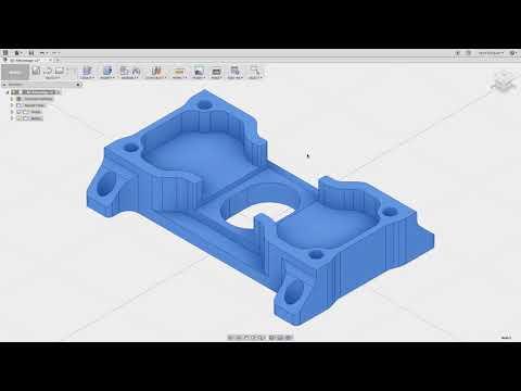 In addition, Type A Machines, Dremel, MakerBot, and Ultimaker printers and more are also available.
DRAWINGS
Easily define the main and additional views of your product, specify the dimensions, tolerances and annotations that are associated with the original 3D model. Thanks to this, any subsequent changes will automatically be reflected in the existing drawing, so you do not have to create it again. Export drawings to your local computer in DWG or PDF format and modify them if necessary in AutoCAD.
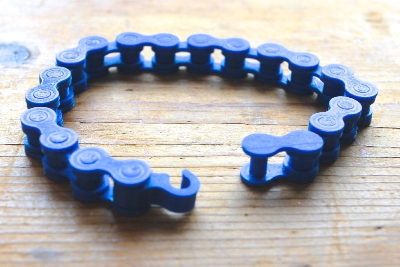
3D Modeling Rules for 3D Printing
As with any other program, Fusion 360 users need to make sure to stick to certain design rules when it comes to 3D printing. A 3D model might look perfect on your screen, but would not be able to exist as a geometrical object in the real world. This is a problem in particular for programs mostly used by visual artists and game developers. Luckily for us, Fusion 360 is mainly used by industrial designers to create functional parts. That's why the transition from virtual 3D model to actual 3D print is quite easy with this software. nine0003
Nevertheless, keep these rules in mind. Chances are you already respect them in Fusion 360 without even knowing that they exist.
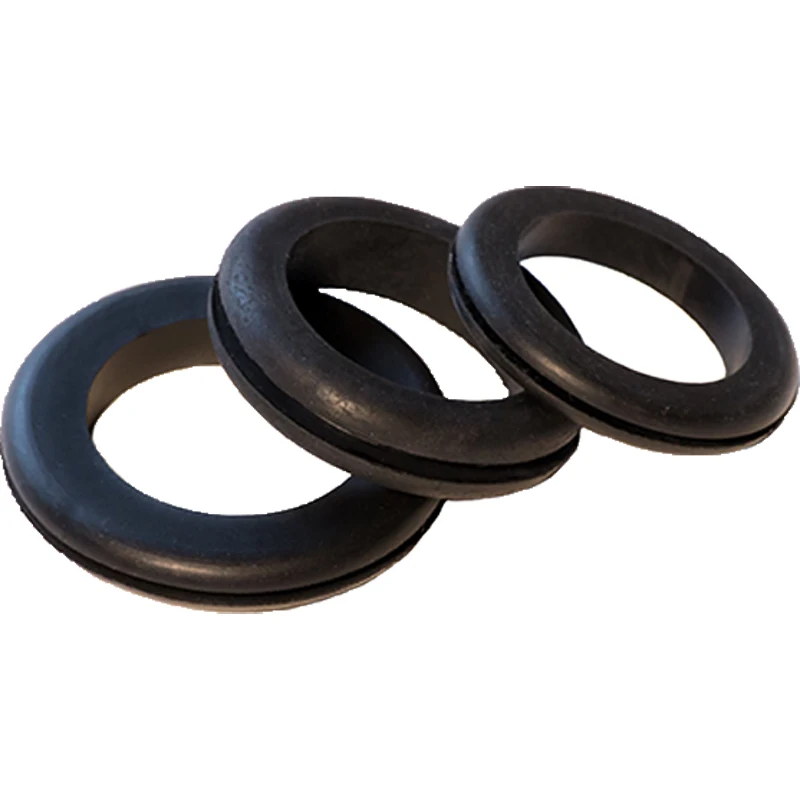
- Wall Thickness: Printers need information about how thick you intend the wall of your object to be (or if you want to print a completely solid model). Therefore, when turning a 3D model into a real 3D print, the wall thickness or volume information of the model is needed. You simply cannot print an object that has a ‘paper-thin’ wall without substance. nine0060
- Watertight: A printable model must not have any holes in its surface. Ask yourself the question: if I were to put water inside my model, would it flow out? If that's the case, then you need to find those holes and close them. Sometimes this process is also called ‘creating a manifold model’
- Grouped Models: While it is possible to export several bodies in a single STL file (so-called grouped models), we recommend you to export one model at a time
Step 2: Select the correct export options.
 nine0013
 You can change the resolution of your STL files by changing the resolution in your CAD software. If you're unsure, select the "high" presets - the safest option for creating an STL file suitable for 3D printing.
Each CAD package has its own way of specifying the STL resolution, but most use two basic parameters: chord height and angle .
The chord height is the maximum distance your software allows between the surface of the original 3D model and the surface of the STL file. Using a lower chord height will help to more accurately represent surface curvature. nine0003
The recommended value for the chord height is 1/20 of the thickness of the 3D printed layer and never less than 0.001 mm (1 micron). The result is always an STL file with perfect fidelity for most 3D printing applications. Exporting at a lower tolerance will not affect the quality of your print as most conventional 3D printers cannot reproduce such a high level of detail.
Angular tolerance limits the angle between the normals of adjacent triangles.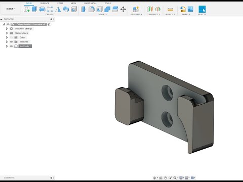 The default setting is often 15 degrees. Some programs also specify this tolerance as a value between 0 and 1. Unless a higher value is needed to achieve smoother surfaces, the default value of 15 degrees (or 0) is recommended. nine0003
Rules of Thumb
- Exporting with a chord height of 0.001mm and 15° of angular tolerance is best for optimal 3D printing results.
- Avoid exporting unnecessarily large STL files.
All CAD programs have their own way to export STL files:
Solidworks: File > Save As... Set Save As to... file type: STL Options > Resolution > Fine (or Custom) > OK. nine0003
3DS Max: 3DS Max Application Menu > Export > StereoLitho (*.STL)
AutoCAD: Output > Send Panel > Export On the command line, type export. In the Export Data dialog box, enter a file name. In the Files of type section, select Lithograph (*.stl) and click Save. Select one or more solid objects. Note. The XYZ coordinates of all objects must be greater than zero.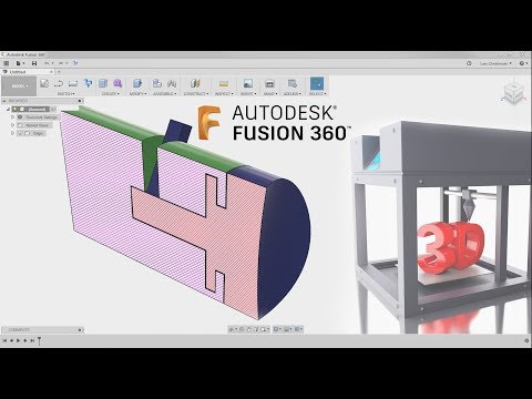 The .stl file extension is automatically added to the file name.
Fusion 360: File > 3D Print. In the Refine/Refine Options section, select the export options. Output > uncheck Send to 3D Print Utility > OK > Save. nine0003
Inventor: File > Print > 3D Print Preview Save copy as... (top left) > Save
Onshape: Right click on bottom right > Export. In the Format section, select STL. Specify the model units. Select export settings.
PTC Creo: File > Save As... > Save a copy of the type change to stereolithography (*.stl). Click OK > a new Export STL dialog box will open. In the Variance Control section, change the export settings. nine0003
Solid Edge: File > Save As... Set the Save As option to STL file type. Options > Select Export Options
ZBrush: Use the Decimation Master to reduce the number of polygons appropriately. Zplugin > 3D Printing Center > Export as STL.
CAD: Engineering
SPLINE MODELING
Create ergonomic shapes with T-spline technology and surface modeling.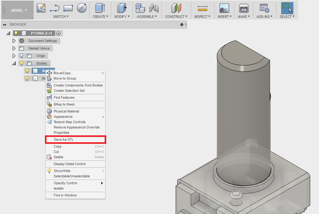 Specify the exact shape of the curvature of surfaces, or directly edit the faces, edges, and vertices of splines manually. nine0003
SOLID STATE MODELING
Solid modeling has never been easier than in Fusion 360. This is largely due to the advent of the project timeline, thanks to which you can easily “roll back” to the desired stage and change it without worrying about updating the structure later. Use familiar top-down and bottom-up design tools such as extrude, revolve, fillet, loft, booleans, and more to create both organic shapes and detailed mechanical products. nine0003
PARAMETRIC SIMULATION
Use parametric dimensions when defining sketches. This will allow you to associate the geometric characteristics of the elements with a certain value or function. Moreover, when one or another parameter is updated, the model will be automatically updated, respectively, changing the associated elements.
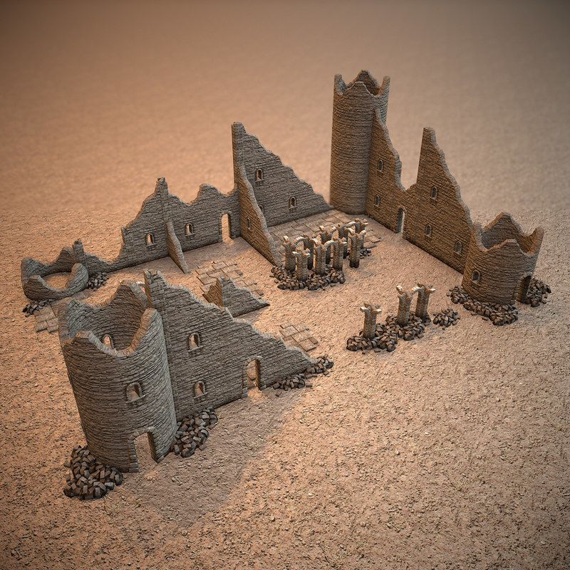
USING GRID MODELS
Import STL and OBJ files scanned from a real object and use them as a base for a future 3D model.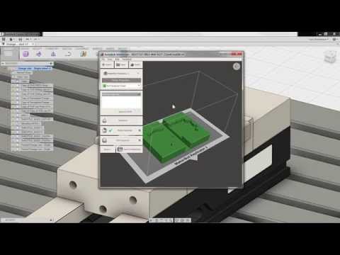 Create a spline surface that follows the mesh profile using the Object Snap tool or use the Pull command to snap the spline vertices to the mesh surface. After that, you can proceed to further refine the model. nine0003
LIBRARIES OF STANDARD COMPONENTS
Fusion 360 comes with a library of standard engineering parts that meet ISO, ANSI, DIN and more standards. Use them as a base for a new project or as building blocks of an existing model, so you don't have to waste time creating them from scratch.
Fusion 360 Features
The new version of the program combines the best features of Autodesk development. Now users are able to carry out using the utility:
- Spline modeling. With the help of technology, you can specify how curved the surface is, it is possible to control it with your hands.
- Solid Modeling. It allows you to apply the usual tools with which you can create organic shapes. And also to detail products.
- Grid models.
 These files allow you to scan objects and use them as the basis for a new 3D model.
 - Parametric modeling. Applying parameters helps link geometric features. nine0060
- Use a library of ready-made solutions. Ready-made solutions can become the basis for the project.
Attention! When the characteristics of the object are set, it is time to process it. Engineering analysis helps to know how the product will behave once it is already manufactured.
Thanks to this function, you can get rid of the detected shortcomings in a timely manner at the very beginning.
The import/export function involves transferring a file to a computer or cloud storage. You receive a notification by mail that the model has been exported. Parts can be assembled in the same place where they were modeled. In Fusion 360 Autodesk, you can designate the features of a moving element: material, movement limits. And kinematic analysis allows you to check the order, the path of interaction of individual connections, understand the finished result, create a believable render, apply animation.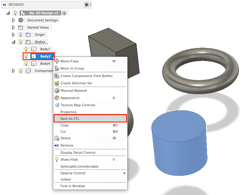 nine0003
Step 1: STL file format information
The STL file format uses a series of linked triangles to recreate the surface geometry of a solid model. As you increase the resolution, more triangles will be used, better approximating the surfaces of the 3D model, but also increasing the size of the STL file.
If you export at too low a resolution, the model will have visible triangles on its surface when printed. This is not desirable in most cases, but can be used to create low poly models with a digital look. nine0003
Increasing the resolution above a certain value is also not recommended, as it does not provide additional benefits: very small details cannot be printed on a 3D printer, so the file size will increase unnecessarily, making processing difficult.
Preparing the 3D Print with Autodesk Print Studio
Autodesk Print Studio takes you through the 3D printing process step by step. The first thing you might want to try is the repair tool, which will automatically detect problems and fix them for you. For example, if your model is not watertight and contains holes in its surface, Print Studio's repair tool will fix this for you. nine0003
The next steps of the process are only important if you use home printers. You can optimize rotation to let the software determine how to best position the body on the print pad. Then you can automatically add supports. Keep in mind that for online services like i.materialise, you do not need to add any supports as we will add those automatically if necessary. Most of our 3D printers (especially those printing in Polyamide) do not even require support structure during their printing process. nine0003
In the last two steps, you can preview your print and export the file.
Course description
You have an idea and it needs visualization. For example, you want to start a furniture production, a line of original jewelry or develop a new car model. Want to see for yourself and show others how it will look like? Autodesk Fusion 360 is the perfect fit for your needs.
Fusion 360 is a comprehensive cloud-based CAD/CAE/CAM tool for industrial design and mechanical engineering. It combines the best of Inventor, Alias, Simulation and other Autodesk software products to create a unique environment that is highly customizable and allows you to design just about anything you can imagine. Fusion 360 is a great solution for hardware start-ups, innovators, small businesses and inventors. The course can also be useful for high school students who plan to choose the profession of engineers, designers, 3D visualizers, etc. nine0003
Fusion 360 benefits:
- this program is easier to learn than many other CAD systems.
- since the system works in the "cloud", it does not load your computer - you do not need to have a powerful PC.
- the system is great for group work: all changes are immediately synchronized in the "cloud".
- you do not need additional software: create a project, visualize and animate it, develop documentation - you can do all this in one program.
 nine0060
 - CAD is free for startups and students: the royalty-free license is renewed every 3 years.
The Fusion 360 lessons in the Expert will introduce you to the tools of the program, and in practical classes you will consolidate the acquired skills. You will learn how to create, analyze and develop a project using engineering analysis tools, motion animation and rendering. In addition, you will be able to prepare and print models on a 3D printer.
After the course, a certificate of the center and an international certificate of Autodesk are issued. nine0003
Would you like to visualize your project? Master Fusion 360 in the "Specialist"!
Autodesk Fusion features
- 360-degree view camera rotation;
- Access to the project in collective mode;
- Calculation of heat transfer and fatigue strength;
- Fully customizable toolbar;
- Object Snap option to repeat mesh profile;
- Function for scanning drawings and real objects; nine0059 Automatic binding of splines to the grid surface;
- Integration with Autodesk Create Design Product Software servers;
- Create, add and edit animations with lots of 3D effects;
- Adjustable focal length, depth of field, lighting type and environment.
Benefits
- 3D printing available;
- Fusion 360 Linux and Mac OS compatible;
- Export project to MP4 video;
- Often used for various startups;
- Support for various CNC axis machines;
- Assembly of parts directly in the simulation environment;
- Differs in simplicity and convenience of the interface;
- High quality dynamic motion animation;
- Various blogs and forums about Autodesk Fusion 360;
- Surface editing of all original elements;
- Creation of additional engineering documentation with the possibility of clarification; nine0060
- Regular software updates from the official website of Autodesk Products.
Disadvantages
System Requirements
Fusion 360 is compatible with the following operating systems: Apple macOS, Big Sur 11.0; Catalina 10.15; Mojave 10.14; High Sierra 10.13, Microsoft Windows 8.1 (64-bit) (until January 2023), Microsoft Windows 10 (64-bit) Semi-Annual Release Channel
CPU must be 64-bit, x86-based, have four cores, 1. 7 GHz or more; 32-bit processor cannot be supported. ARM-based processors can only be partially supported with Rosetta 2.
Memory of 4 GB or more of RAM (preferably an integrated graphics card with at least 6 GB of memory). The graphics card may only be supported for DirectX 11 or later. A dedicated GPU requires at least 1 GB of video memory. The integrated graphics card must have at least 6 GB of memory.
The disk must have 3 GB free for data storage. The screen resolution should be at least 1366 x 768 and 19 is recommended20 x 1080 or higher at 100% screen size. The pointing device is compatible with a HID mouse or trackpad, Wacom tablet is supported, as well as 3Dconnexion SpaceMouse.
Carefully! The Internet must have a download speed of at least 2.5 Mbps, and for uploading at least 500 Kbps.
The program depends on NET Framework 4.5, SSL 3.0, TLS 1.2, or later. For full-fledged work, a central processor of at least 3 GHz is recommended, so that there are at least 6 cores.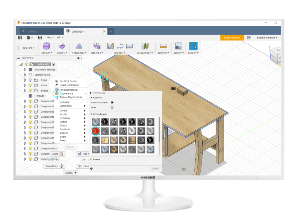 Required memory from 8 GB of RAM. 4 GB and DirectX 12 support are needed in the GPU. nine0003
Full description
Fusion 360 is a professional program for working with CAD, CAE and CAM files. Powerful functionality allows you to create 3D models of any complexity and perform any operations with them. Often used in the field of computer-aided design and mechanical engineering.
The software allows you to conduct a detailed engineering analysis, thanks to which you can quickly identify the vulnerabilities of the product being created and get rid of flaws in a timely manner. It is worth noting the A360 function (cloud), with which you can share the results of design calculations with colleagues, as well as discuss the information you are interested in in real time. nine0003
Fine adjustments of the surface curvature shape are available, you can easily edit faces, edges and spline vertices. With solid modeling, it is possible to undo every action taken, up to the original structure. Fusion 360 has the following tools: extrude, revolve, fillet, boolean operations, and so on.
You can manually control literally all the parameters of the parts and model a truly unique project. The user can use templates with certain geometric characteristics of the components. A special Motion Study simulation tool will show how your assembly will behave in reality, taking into account the interactions of moving joints in accordance with the standards. nine0003
Fusion 360 provides the user with a convenient import of files from other similar CAD applications. Export to 3D CAD, OBJ, STL, F3D, SLDPRT, SAT, IGES, SMT, FBX, STEP, DWG and many more. You can save materials both on the hard drive of your PC and in the cloud storage. There is an option to preview the render and print on a 3D printer.
File Resolution of 3D Print
On the right-hand side of your screen, you will see a window with additional 3D printing settings to choose from. These are mainly about the resolution of your 3D print. A very low resolution will make the print look somewhat pixelated. A resolution that is too high will make the file very - or even too heavy - to handle. nine0003
Besides the pre-defined resolution options of “low, medium or high”, you can click on “Refinement Options” to customize the settings. We recommend a deviation of 0.01 millimeters for 3D printing with i.materialise. This resolution will guarantee a print of the highest possible detail while ensuring that the data won't be too big.
Fusion 360 Tutorials
- Training term: material with educational content.
- Content form: lectures + video assignments. nine0060
- Communication with the teacher: no.
- Registration term for the stream: no restrictions.
- Required level of knowledge: for beginners.
- Homework check: no check.
Tutorial: Fusion 360 is a cloud-based collaborative development tool. Includes full cycle tools - from concept (idea) to creating forms embodied in physical material (wood, metal, plastic).
Includes modules:
- CAD (CAD) - automatic design system. Allows you to create flexibly editable designs, with a very high degree of automation of this creation
- CAM - process (and software) for preparing a part for processing on machine tools with numerical control (CNC)
- CAE - calculation and simulation of physical processes taken into account in product design. For example, stress analysis, kinematics, refractoriness, etc.
Fusion 360 tutorials are also useful for modelers working in games or visual effects. The program is quite intuitive, has a low threshold of entry and, almost completely, is able to replace hard-surface modeling, in particular, direct (Direct) modeling. And, in some cases, the rendering of the final images. nine0003
Advantages of the program
Among the main advantages that distinguish Fusion 3d:
- Leverage the cloud to access files on the go, update easily, and quickly troubleshoot security issues.
- Accessibility of the interface to each user.
- Good feedback from the support team.
- Easy to work with both Windows and Mac OS.
- A wide range of creative possibilities, involving different ways of creating three-dimensional figures, visualization of interiors, directions of cutters, other design or engineering work. nine0060
- Ability to work with several people on one project, which is convenient in production.
Sergey Gubanov Fundamentals of modeling in the Fusion 360 environment
The manual contains a set of tasks and guidelines for their implementation, aimed at learning the basic techniques of working in the software package "Fundamentals of modeling in the Fusion 360 environment ".
CAE: engineering analysis
ENGINEERING ANALYSIS
Understanding how a product will behave in a real environment before it goes into production can save you time and money. Use engineering analysis tools to identify the most vulnerable areas of a future product and fix them at the design stage. Share the results of your calculations with the rest of the team using Fusion Team. At the moment, strength and modal analysis, heat transfer and fatigue strength calculations are available.
WORKING WITH ASSEMBLY
Assemble parts directly in the same environment in which they were modeled. Make the connections of the parts rigid, for example, as they are currently built, or specify a more detailed specifics of the movable connection: rotational, translational, planar, spherical, helical, etc. Specify the limits of movement to achieve exactly the type of connection that should be in reality and immediately preview any kinematic changes.
KINEMATIC ANALYSIS
See how the assembly would behave in real life by activating all connections in the Motion Study environment. Establish the order and method of interaction of moving joints and evaluate the final picture of the kinematics. View the dynamic motion animation or play it in reverse.
RENDER
Create photorealistic images with Fusion 360, taking advantage of the power of Autodesk cloud servers. Take advantage of the huge library of available materials such as translucent plastics, wood, metal, glass and composites. Edit existing materials and customize them for your project. Adjust camera settings such as focal length, depth of field, lighting type and environment. nine0003
ANIMATION
Animate your assembly using flexible tools to set up camera, transitions, detail fade in/out, manual or automatic assembly explosion, informational text callouts, and more. Share your animation after exporting it to MP4 video.
Interface
An integral part of Autodesk Fusion is a data panel that facilitates interaction with projects, allowing them to be saved, opened, and shared while working with a team. There is an application control panel. The main menu of the program is File. The project is saved in Save. The last action is canceled or returned to Undo, Redo. nine0003
In the panel of context-sensitive tools, which, in a different way, is called the toolbar, there are sections for various work with the project - drawing sketches, creating sculptures, drawings.