Fine tuning 3d printer
HowTo Calibrate, Tune and Fine Tune your printer and filament - No category - Talk Manufacturing
SOC3D
#1
3d printers are quite dumb as far as electronics go in the sense that there is a lot going on during a print which is assumed by the electronics. 99% of the time the electronics are assuming incorrectly.
If you want better prints, tune your printer to your filament.
Ideally you would do most of these steps for every print or every individual roll of filament. If you use a single brand you could setup profiles for each material, if you use a single brand and single material you could do this once. You should do this for every spool of filament or every print.
Step 1: Calibrate your extruder (This only needs to be done when something changes)
- Disconnect your hotend from the extruder.
- Cut the filament flush with whatever fitting you have.
- Using whatever interface you use to control your printer extrude 100mm/10cm of filament.
- Your firmware may have a safety temperature preventing cold extrusion. If this is the case you will have to bring your hotend up to temp in order to extrude filament.
- Cut the filament and repeat this procedure two more times.
- Measure the three pieces of filament.
- Get an average (add the three measurements and divide by 300).
- If your average is not close to 100 you need to change your extruder steps per mm. Take the current steps per mm and divide it by (your average/100).
- Repeat until you are happy.
Step 2: Calibrate your filament diameter, do this every print!
Using a caliper, measure your filament diameter at several locations. Average out the measurements, at least 3, and enter that into your slicer under filament diameter.
Step 3: calibrate your z height and first layer. Do this whenever something changes in your printer.
- Print a single layer (of say a 20*20mm cube) with your first layer at 100% height and width.
- Using a caliper measure the print in several places (at least 8) and adjust your bed or gcode z offset.
- Repeat until you are happy.
Step 4: calibrate your extrusion multiplier!
Do this every print, to be a little lazy every roll, to be really lazy every brand and material, if your slacker only once
- Print out a cube
- (20mmx20mm would be nice)
- in vase mode (single outline, no infill, no top or bottom layers)
- set your extrusion multiplier to 1
- set your extrusion width to equal the width of your nozzle.
- Measure the walls with a caliper in several places (at least 8) and get an average.
- Change your extrusion multiplier: new multiplier = old multiplier x (extrusion width / average measurement)
- Repeat until you are happy.
Step 4.5: PID tune your bed and hotend.
Before and after you calibrate temperatures and any time you change a fan or move something or a season changes. PID tune your hotend and bed to keep your temperature fluctuations to a minimum.
- M303 E(Extruder 0 for hotend 1 for bed) C(# of cycles 3-8) S(Desired Temperature)
- M303 E0 C5 S180 = PLA Hotend tune for 5 cycles
Step 5: calibrate your temperatures.
Do this for every different filament (color, brand, material, etc)
- Grab a temperature calibration tower off thingiverse: Customizable Temp Calibration Tower by eibwen - Thingiverse
- Set the temperature range to the range listed on your filament or by the manufacturer.
- Print the calibration tower and choose the best temp.
Step 6: Calibrate your fan speed.
(I have a Delta with three really powerful layer fans. If they all three run at 100% the hotend loses temp)
- Print your calibration tower again but change the fan speed vs the extruder temp.
- Choose the best fan speed for the finish you desire.
Step 6.5: PID tune your hotend again with the layer fan set to the ideal speed!
As noted above if your fans in any way change the temperature of your hotend (all layer fans do) you should PID tune the hotend with the fan set at the most common speed to keep temperature fluctuations to a minimum.
I left a lot of details out and some things are vague. Let me know what should be added and I’ll edit it. Also my formulas may be off.
13 Likes
3dprintingguy
#2
thanks for the post!
Christian_Simon
#3
Hi,
I have a Velleman Vertex K8400 printer with a 0. 35 mm standard nozzle. Printing with 1.75 mm PLA without a heated bed.
Step 1: Estep/mm was calibrated from 200 to 140
Step 2: Measured the filament between 1.65 mm and 1.75 mm - On average about 1.73 mm
Step 3: Don’t understand it. Am I to print only the first layer of a Cube, so rectangle of 20x20mm? what am I supposed to measure, and adjusting the bed - are you referring to the bed height? How should one use the measurements to adjust the bed or code z offset?
Step 4: Measured 9 times between 0.45 mm and 0.59 mm . avg. 0.50 mm = New multiplier 0.7
Step 4.5: Didn’t understand this either
Step 5: Not yet tested
Step 6: Not yet tested
On step 4: The cube that I printed is under extruded at 1.0 extrusion multiplier… Step 4 recommend to use 0.7 - is this correct?
SOC3D
#4
Step 3 you should print a single layer of anything at 100% first layer height and 100% first layer width.
You then measure the height of the print in several places in order to find out if your z height is set correctly.
If your layer height is .2mm your part should measure .2 mm.
On Step 4 what was your line width set to? With a .35mm nozzle you should set your extrusion multiplier to 1.0 your line width to .35mm your variance should not be more than 100 micron really it should be within 20-40 micron.
If your extrusion is looking weird or under during this you may just have bad filament? If it’s PLA try a new roll or try heating/vacuuming the moisture out of the filament.
Can you attach a picture of the cube you printed and tell me a little more about the filament, brand - how old is it - how is it stored.
Christian_Simon
#5
Hi,
Follow up question to Step 3: So if I measure 0.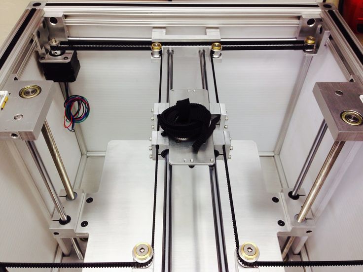 3 mm height when the layer height should be 0.2mm, does this indicate that my nozzle is 0.1 mm to high from the bed?
Step 4: (first picture, and print to the left on the second picture)
See pictures attached from the first 20mmx20mm cube test that had an average wall thickness of 0.5 mm at 1.0 extrusion multiplier. (first picture)
Step 4 - take 2: (second picture, and middle print)
Based on the first test I reduced the extrusion multiplier to 0.84 and did a new print. I printed this only 10 mm tall to see the difference between the two.
Printed wall size was then measured to 0.40-0.43 mm and average of 0.42 mm
Step 4 - take 3: (second picture, print to the right)
Based on the second test I decided to use the new Beta version of Cura (2.1) rather than the Cura (15.04.5). I set the layer height to 0.06 mm, but kept the extortion multiplier at 0.84
Printed wall size was then measured to 0.35-0.42 or an average of 0. 38 mm (so getting fairly close now to the 0.35 mm target)
Regarding the question on the filament. I bought the Velleman own PLA 1KG 1.75 mm filament. It was opened 2 weeks ago. Since then it has been stored on the printer in room temperature of about 23 degree C. Do not see any info on production date.
SOC3D
#6
There is something wrong with your – Filament or Hotend Temperature or Extruder – the prints in those pictures are not due to calibration or tuning of extrusion.
Can you try printing a temperature tower off thingiverse? You should use the temperature range listed on your filament or if there is no range, 5 degree celsius steps from 180 degrees to 220 degrees.
You should also run PID tuning (M303) on your hotend to ensure you are getting a consistent temperature.
Christian_Simon
#7
Hi,
I will try to print the temperature tower tomorrow. I tried to print this today, and it turned out pretty well I think.
SOC3D
#8
Have you run the PID tuning on your hotend?
Mitcheg1
#9
I’m similarly confused about step 3. My first layer averaged 0.33mm when I had a 0. 2mm layer height. So does this indicate my nozzle is too close or too far from from the bed? Do I set my z height to -0.13mm?
SOC3D
#10
That indicates the nozzle is to far away. A negative number should move the nozzle closer to the bed. Should.
zxo3d
#15
It’s been a few years since this was published and nobody has mentioned that you don’t divide by 300 to get the average extrusion… You divide by 3… Update it please as I use this for new printer owners.
How To Calibrate A 3D Printer [Quick and Simple Guide]
Want to calibrate your 3D printer to achieve the best possible prints? Here's a quick guide that you can improve the quality of your 3D prints even more!
By Justin Evans
So you’ve bought yourself a brand new 3D printer and you can’t wait to get started. Trouble is, you can’t just jump right in. Before that, you’ll have to know how and why 3D printers are calibrated. That’s where we come in.
This guide will explain how you can calibrate your 3D printer. We’ll also be covering a little of the science behind it all, but we’ll try to keep things as easily understandable as possible so don’t worry. Now, let’s start by addressing the common question: “why do we need to calibrate at all?”.
Table of ContentsShow
What Is Calibration For?
Imagine you’re a baker. You’ve finally created a recipe that makes perfect bread each and every time. Congratulations! But fans keep writing to you telling you the recipe doesn’t work. After a while, you realize it’s because they’re all using the wrong size of baking tin. So how could this have been avoided?
Calibration allows 3D printers to avoid scenarios like this. Essentially, calibration helps ensure every print comes out exactly the same, regardless of the equipment used to create it. Nothing lopsided will be printed (unless that’s your intention), and your creations will be identical every time.
Preparing For Calibration
3D printers are very complex machines, and as such, calibration isn’t a one-click kind of task. We’d recommend setting aside at least half an hour to allow you to really get to the bottom of any issues that might occur.
You should also note that all printers are calibrated differently. Some have physical adjustment levers while others are controlled entirely via software. As such, the advice we’ll be giving should be used as a general guideline and not taken as concrete instructions.
Now, there are three main areas of your printer that require calibration: the extruder, the base plate, and the various motors. Below, we’ll explain how to attend to each of these parts.
How To Calibrate The Extruder
There are two main problems the extruder (the part that spits out hot filament) can have. The first is over-extrusion, where too much filament is used, and the second is under-extrusion, where too little is. You should also consider the filament thickness, but this is easy enough to correct if it’s wrong.
To see if your printer is over or under-extruding, you’ll need a ruler, measuring tape, or set of calipers. Make two marks on the filament 100mm apart and align the bottom mark with the top of the extruder. Next, in your software, set the extrude length value to “100” and tell it to extrude.
If everything has worked as intended, the top mark will now be aligned perfectly with the top of the extruder. If not, you’ve got some work to do. You’ll have to adjust the extrusion (sometimes called “Flow”) percentage until the top mark aligns correctly.
How To Calibrate The X, Y, and Z Motors
Okay, the next step is to make sure your printer has its measurements right. To do this, use a piece of tape to mark two areas that are 100mm apart on the base plate. Position the nozzle over one, tell the printer to move 100mm in the correct direction and see if it ends up exactly over the tape.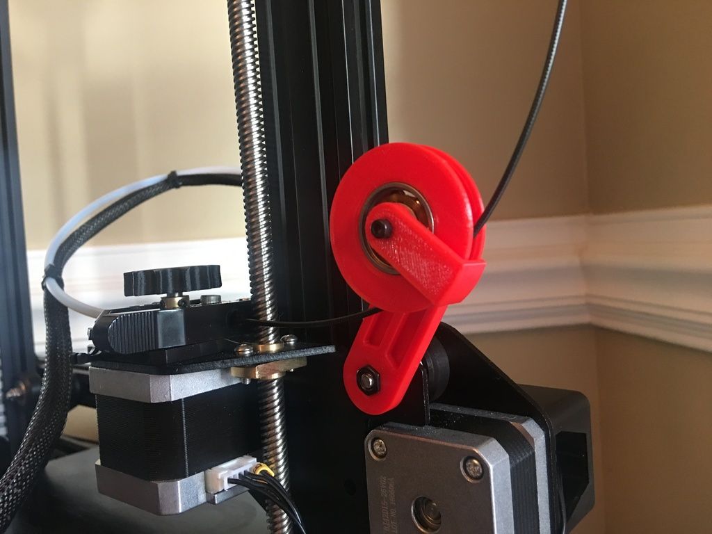
You should note that it’s likely not going to be ideal on the first try. 100.01mm isn’t the same as exactly 100mm, but these small differences can have large repercussions later on so it’s best to address them now. Adjust the M92 values for both the X and Y axes until it works perfectly.
For the Z motor, you’re going to want to use a ruler. Stand it vertically on the print bed and move the Z axis by 100mm. After this point, the process is the same: just change the M92 values until it moves exactly 100mm each time.
How To Calibrate The Base Plate
If you’ve noticed that your layers are too thin or that filament is gathered around the nozzle, you’ll likely want to level your base plate. This is so you can ensure the nozzle is the same distance from the base at all times. So how do you do this?
Start by centering the print head. You’ll likely have been provided with an index card, so place this between the print head and the base plate. By editing the Z-axis end stop variable, you can fine-tune the head’s distance from the base.
Most printers will have screws you can turn at each corner. Adjust these until you feel a slight resistance when you try to move the index card – you should still be able to move the card, but not freely. When you achieve this, you’re done!
Conclusion
3D printers can be difficult to get the hang of as there are dozens of options to tinker with at first. That said, there are only a few steps to take whenever you make a change. We’ve addressed these above and now, hopefully, you’re ready to start printing. Good luck and most importantly, have fun.
What Is 3D Printing?
3D printer fine-tuning, flow and extruder settings
Extrusion settings. Checking and Adjusting Feed Length Accuracy
This is the very first adjustment you need to make before adjusting flow and layer.
To adjust, you can remove the tube from the hotend, but if you are afraid to touch it, then you need to remove the plastic from the tube to the feeder wheel and remove the tube from the fastener. The plastic bar should stick out.
For measurements, we will need a starting point, which, when removing the tube, will be the end of the tube, and with the option on the other hand, the beginning will be the end of the fastener.
Trim the protruding thread flush with the retainer so that the thread is flush with the hole.
Further, to carry out all the manipulations, we need the Repetier-Host program. There, the console is more convenient and the EEPROM values are easier to edit.
We go into the application, connect the printer and press ALT + E. The EEPROM values are displayed on the screen.
Printer EEPROMWe are interested in the "E axis resolution" value. This is the number of motor steps to extrude 1mm of bar.
First of all, you need to heat the extruder, otherwise the printer will not let you start to press the plastic. We do this with the command M109 S180 , which will tell the printer to heat the nozzle to 180 degrees, it will be enough for us, anyway, he does not take part.
As soon as the nozzle heats up, we need to feed some convenient amount of plastic from the coil, convenient for calculations. 100mm or 200mm, whichever is easier to measure. Press out 100 with the command G1 F400 E100 .
As soon as the feed stops, you can turn off the heating of the nozzle with the M109 commandS0. In the meantime, we have a plastic bar sticking out theoretically 100mm long.
Now it is necessary to cut off this piece in the same way flush and start measuring it.
As you can see, we squeezed out 102mm of plastic. Therefore, we need to recalculate the number of steps / mm. This is done as follows:
- 102mm of our bar is 98.5 steps (the current value of "E axis resolution" from the printer's memory)
- 100mm of the desired is "X"
- X = 100*98.5/102
- X = 96.56 (can be rounded up to 96.5 or the nearest integer 97)
Enter a new value in the "E axis resolution" field, click OK. The value is stored in memory and the setting is completed.
The procedure can be repeated several times for fine tuning or to make sure everything is done correctly.
Flow setting
Printing a 20mm by 20mm cube (download cube model) with the following settings:
- Flow: 100%
- Infill: 0%
- Number of Wall Lines: 1
- Lid Layers: 0
- If Alternate Wall or Vase Mode is enabled, turn both off.
It should look like this in the slicer:
Print and start measuring. We measure all the walls in several places. Let's say on each wall to carry out 3 measurements in its different places. As a result, we get 12 values, among which we consider the arithmetic mean.
Let's say the arithmetic mean is 0.44. Calculate the flow rate:
100% of the set flow * current line thickness (printed with nozzle 0.4) / measured thickness. We get 100*0.4/0.44 = 90. 9. You can also round up to 91% and enter this value in the slicer settings.
Next, print the cube again to make sure the new settings are correct. If you are not satisfied with the result, calibrate again.
Magic Numbers
Author of this study: CHEP. The material on magic numbers is a free translation.
I will not go deep into the theory of operation of a stepper motor. You can always find it on the Internet, otherwise you will get a textbook.
What are the "magic numbers"?
The stepper motors on the Anycubic i3 MEGA have 1.8 degree steps, which equals 200 steps per revolution. This, if I may say so, is his "natural steps" or "natural positions of the shaft." These positions are as accurate as possible.
Microsteps is the division of each step into a certain number of steps. This is controlled by the motor driver. Microstepping is a less precise position. Firstly, the accuracy of the drive is hindered by the geometric imperfection of the rotor and stator of the motor, non-ideal windings, gaps in the shaft bearings, etc. As a result, the engine always performs steps with some error (typically 5% of the full step value) , and the absolute value of the error is constant for any selected microstepping mode! In addition, in many drivers the motor control is also less than ideal, which leads to additional uneven movement in microstep mode.
The Anycubic i3 MEGA printer on the Z-axis has travel shafts with the following parameters:
- Outer diameter: 8mm
- Pitch: 2mm
- Nut lift per revolution: 8mm
In view of simple calculations, knowing that the engine makes 200 steps per revolution and for this revolution the rise along the Z axis will be 8mm, we get 8mm / 200 steps = 0.04mm. This is the "magic number".
At any print layer height multiple of 0.04mm (0.12, 0.16, 0.2, etc.) the motor will make a “natural step”, hence the most accurate movement, which should result in a uniform layer.
Instructions for setting up the entire mechanics of a 3D printer: from belts to speeds
The quality of the printed models directly depends on the mechanics of the printer, namely on its correct settings. Any elements of the printer wear out over time, so the printer must be set up at least once every 5-6 kg of printed filament. With the help of the short instructions described in this guide, you can quickly and easily set up the mechanics of your printer: belt tension, motor current, motor steps, acceleration, jerk and speed.
Mechanics includes
3D printers of any design always contain the same things: Axes and rails along which the elements of the printer move and motors with belts that set these elements in motion. In a classic printer design, there are at least 3 motors (one for each axis), 3 rails (one for each axis) and an electronics board that controls the motors. The latter can hardly be called part of the mechanics, but since it controls the engines, it also indirectly affects the quality of the model.
Printing defects due to mechanical problems
Before changing anything in the printer, you need to decide what exactly needs to be configured. Often defects are visible visually. Our blog has an article about most printing defects, which details the reasons for their occurrence. The following is a list of defects and what element of mechanics they are associated with:
-
Layer shifting - Belts, Motor current, Guides
-
Ringing - Guides, Speed
-
Incorrect model geometry - Guides, Motor steps, belts
As you can see, all the above problems do not interfere with the printing process itself, but the result leaves much to be desired. Sometimes mechanical errors can completely stop the printer from working. Therefore, it is better not to take the situation to extremes and, if any problems arise, immediately start checking and configuring the 3D printer.
How to save settings
To fix some defects, you need to change the printer software settings. Therefore, before adjusting the mechanics, it is necessary to understand how to properly store the settings inside the printer. There are 3 ways to do this:
All settings are located in the corresponding menu of the printer
Depending on your firmware, this manual will indicate code sections for MARLIN firmware in the configuration.h file
We first enter the parameters into the printer and then store them in EEPROM - the internal memory of the microcontroller. Or paste all the necessary settings at the beginning of GCODE. To learn how to do this, read our article on working with GCODE and creating macros.
To save to EEPROM, you need to send the printer a command to change some value (which can also be inserted into the initial GCODE), and then send the M500 command (save the current settings to permanent memory). The EEPROM function must be enabled in the firmware, for this you need to remove two slashes in the line:
//#define EEPROM_SETTINGS
Whichever option you choose, you should be careful when using any commands. You will not be able to harm the printer in any way when changing the settings, but if you make a mistake, you will have to look for the cause of possible further problems for a long time.
Setup instructions
Now you can start setting up the printer itself. If you decide to set several parameters at once, then it is better to use the order of adjustments as in the article, since some of the settings are related to each other and if you use the wrong order, adjusting one element of the mechanics will override the settings of another element. For example, you should not adjust the motor steps before tightening the belts, as changing the length of the belts will change the "true" steps per millimeter of the motors. Also, before setting up, you must make sure that there are no backlashes in the printer frame, tighten all belts.
Belts
The first thing to start setting up the printer is the belts. They directly affect the geometry of the model and, when pulled too much, they cause a lot of problems: displacement of layers, changes in geometry, ripples. First you need to make sure the belt is intact. To do this, look at the entire belt, especially the areas where the belts bend. If the belt has outlived its usefulness, then you can see a section of the belt where the distance between the teeth has greatly increased and a metal wire (cord) is visible between them. This means that it's time to completely change the belt.
Broken belt with broken cords
If the belt is intact or you have already replaced it, then you can proceed to the next step. Depending on the design of your printer, you need to move the roller through which the belt passes. The tension should be such that the carriage or table moves effortlessly, but at the same time, when moving quickly, the belt should not slip the teeth on the motor gear. Adjust the tension of the belts on each axis of the printer using this method.
Tip: if your printer came with a belt tensioner in the form of a spring attached to the belt itself, remove it. Due to the flexibility of this tensioner, printing defects will occur, such as protruding corners on the model.
It is better to adjust the belt without using this tensioner.
Belt tensioner
Current motors
As we know from the school physics course, the power of the engine depends on the voltage and current strength. Since the voltage on all printer electronics is the same everywhere, the only thing that can be changed is the current on the motor. More precisely, it should be said the maximum current that the driver will supply to the motors. To change this limit, you need to climb inside the case and find the printer board. On it you will see the printer driver. We are interested in a small potentiometer on the driver itself (in the picture below it is indicated as a tuning resistor).
Potentiometer location example on driver
For adjustment, you will need a voltmeter and a small Phillips or flathead screwdriver. Before proceeding further, it is necessary to calculate the maximum current supplied to the motors. Different formulas are used for different drivers, the most popular ones will be listed in the table below:
| Driver name | Formula | Explanations |
| A4988 | Vref = Imax * 1.25 for R100 | To understand which formula to use, you need to find a resistor with the signature R100 or R050 on the driver. They are located next to the driver chip. |
| DRV8825 | Vref = Imax / 2 | |
| LV8729 | Vref = Imax / 2 | |
| TMC2208 TMC2100 TMC2130 | Vref = Imax * 1.41 | One formula for all drivers |
The value of the maximum current (Imax) depends on the motor controlled by the driver. This can be found in the engine specification or on the sticker on it. The following are the currents for the most popular motor models:
17HS4401 - current 1.7 A
17HS8401 - current 1.8 A
17HS4402 - current 1.3 A
Substituting the value into the formula, we get the Vref value for the maximum current supplied to the motor. But at this value, the engine will get very hot, so the resulting Vref value must be multiplied by 0.7. For example, for a motor with a maximum current of 1.5 A and a TMC 2208 driver:
Vref=1.5*1.41*0.7=1.48V
Now the resulting value can be used when configuring on the printer itself. To do this, disconnect the wires going to the motors, turn on the printer and place one voltmeter probe in the center of the trimmer, and the second probe to the negative terminal on the power supply (you can also use the negative terminal on the printer board and the contact on the driver, labeled as GND). You will see some value on the voltmeter screen. Turn the trimmer clockwise to decrease the Vref value and counterclockwise to increase it.
Attention: you should not specify a Vref value higher than the maximum calculated for your engine! Otherwise, the engine will soon break down!
Once you have adjusted the value on the drivers, you can turn off the power to the printer, connect the motor wires, and put the case back together. This completes the driver setup.
Motor steps
When setting up motor steps, you will need a ruler. For convenience, you can use the program Repetier-Host. The adjustment for each of the three axes occurs according to the same algorithm:
-
Set the caret to zero coordinates (Autohome or G28)
-
Move the carriage some distance
-
We measure how far the carriage has traveled
-
We calculate the correct number of steps per millimeter using the formula:
True steps per millimeter = current steps per millimeter * reported distance / distance traveled
For example, if the printer was set to 100 steps/mm, we tell the printer to move 80mm and the printer travels 87. 5mm. Then the correct steps per millimeter would be 100 * 80 / 87.5 = 91.42 steps/mm. For the convenience of measurements, you can fix a ruler on the table, and a thin object, such as a needle or pin, on the carriage. Then it will be possible to accurately measure the distance traveled. The extruder uses a partially different algorithm to measure distance:
-
Inserting plastic into the extruder
-
Cut it right at the outlet
-
We give the printer a command to stretch the plastic a certain distance (at least 100 millimeters)
-
Cutting plastic again
-
We measure the length of the resulting piece of plastic
-
We use the formula from the previous algorithm
Next, the settings data must be inserted into the firmware in the line:
#define DEFAULT_AXIS_STEPS_PER_UNIT {X,Y,Z,E0}
X,Y,Z and E0 should be replaced by the steps per millimeter for each of the axes, respectively. Otherwise, you need to insert this line into the initial GCODE:
M92 Ennn Xnnn Ynnn Znnn
Instead of nnn in each of the parameters, you must substitute the steps per millimeter for each axis. If you want to adjust the steps only for not all axes, then you can remove unnecessary parameters.
Acceleration
This parameter is responsible for the rate of change of speed. That is, how fast the printer will change its speed. This affects the nature of the movement of the hot end relative to the table. If the acceleration is too small, then the printer will print slowly, if it is too large, then the outer surface of the model will have visual defects: fading waves will be visible near each of the corners, as in the picture below.
To set up acceleration, you need to follow simple steps:
-
Cut a model of a standard test cube with a wall thickness equal to one nozzle diameter, without filling and top layers, bottom 2-3 layers;
-
Open GCODE file in notepad;
-
Find the G28 command at the very beginning and insert the line data after it:
M201 X5000 Y5000
M204 P500 T500
-
Save the changes, print the model according to the received GCODE and note at what parameters P and T it was printed;
-
Open the same GCODE file and change the P and T values on the second line, adding 500 to each;
-
Repeat steps 4-5 at least 3 times;
As a result, you will get several test cubes, some of which will show waves at the corners. Choose the cube that is printed with the highest P and T parameters, but that no waves can be seen on it. The number in parameter P will be the desired acceleration value. To save this value, you need to find 2 lines in the firmware:
#define DEFAULT_MAX_ACCELERATION {X,Y,Z,E0}
#define DEFAULT_ACCELERATION {nnn}
Instead of X and Y, you should put an acceleration twice as high as found earlier. And instead of nnn, you need to put the acceleration value found earlier. Otherwise, you need to insert a line in the initial GCODE:
M204 Pnnn Tnnn
In the parameters P and T, you need to put the value of the found acceleration. After that, the acceleration setting can be considered complete.
Jerk
A jerk indicates the speed with which to start accelerating. It affects the model in a similar way as acceleration: it creates ripples around the corners of the model. But it also increases the protrusion of the corners if the jerk is too small. The jerk setting is also similar to the acceleration setting:
-
Cut a model of a standard test cube with a wall thickness equal to one nozzle diameter, without filling and top layers, bottom 2-3 layers.
-
Open GCODE file in notepad
-
Find the G28 command at the very beginning and insert the line data after it:
M205 X5 Y5
-
Save the changes, print the model according to the received GCODE and note at what X and Y parameters it was printed
-
Open the same GCODE file and change the X and Y values on the second line, adding 2 to each
-
Repeat steps 4-5 at least 3 times
As a result, you will get several cubes. Find a non-rippled cube printed at the highest X and Y settings. This will be the jerk value for your printer. To save them, you need to find the line in the firmware:
#define DEFAULT_XJERKnnn
#define DEFAULT_YJERKnnn
It is necessary to substitute the jerk values for the X and Y axes, respectively. Otherwise, you need to substitute the command in the starting GCODE:
M205
Instead of nnn, you need to substitute the jerk value found earlier. This completes the jerk setting.
Speed
In fact, there are many different speed parameters, the values \u200b\u200bof which vary greatly. Let's take a look at the main ones:
This parameter is responsible for moving the nozzle without extruding plastic. The value is in the range from 80 to 120 mm/s. Limited only by the maximum speed at which the motors can rotate. Does not affect the model
This speed is important because it indirectly affects the adhesion of the model to the table. Usually lies between 15 and 30 mm/s
-Print speed of inner walls
Usually set to about 60 mm/s, it only affects the strength of the model. Depends on the maximum amount of plastic that the extruder can push through the nozzle
-Speed of printing outer walls
Usually about half the printing speed of the inner walls (30 mm / s).