Fea 3d printing
FEA and 3D Printing - Challenges and Potential Workarounds
3D printing is challenging the ways that Finite Element Analysis (FEA) methods are traditionally employed to assess the structural adequacy of engineered components. Thanks to 3D printing technologies, it is no longer a safe assumption that materials can simply be modelled in FEA software as uniform homogeneous solids. Indeed, a 3D printed cube of material is not what it appears to be on the outside, as it can be built from the ground-up, piece by piece and may actually possess a complex internal cross section composed of intricate void spaces such as complex hexagonal honeycomb structures.
One admittedly admirable goal of 3D printing is the creation of material structures that are precisely optimized to fit a particular structural application while at the same time minimizing the material mass used to create the part. However, in the process, the technology practically turns on its head decades of material strength testing and characterization. After all, the material stress-strain tensile test curves that form the backbone of every undergraduate materials strength class were all created using solid, homogeneous coupons produced from traditional manufacturing methods.
It’s from these empirical testing curves that much of the basic parameters characterizing material strength are derived – everything from the determination of material yield strength to measurements of toughness and ductility. 3D printing processes are able to create materials that, while comprised of traditional engineering isotropic materials, may not actually be isotropic.
Profiles, material scrutiny, and the pace of emergent technologiesAs designers look to place these printed structural parts into engineered systems, they will face a challenge ensuring that the materials are structurally adequate for use in the particular applications as there simply isn’t a significant amount of material strength testing verification standards, publications, or even documentation available. 3D printed profiles haven’t yet undergone this level of material scrutiny yet, and as a result, any engineer looking to employ a printed component into a system must argue that even in the absence of rigorous standardized testing methods, (ASTM or MIL standard), the parts will be structurally acceptable in a given application.
Adding to this problem is that there are many different types of emerging 3D printing processes. A simple internet search reveals dozens of proprietary methods being independently developed all over the world, and only a handful have really undergone even rudimentary testing/verification standards developed alongside them.
This says nothing at all about testing methods used to develop criteria for more advanced fields of material mechanics such as fracture mechanics or high temperature creep behavior. It’s also relatively easy to find a hobbyist on YouTube performing all manner of testing on all varieties of printed components, but there are still miles to go in the race to develop standards for printed materials to be used in anything remotely resembling a safety critical component.
Within the FEA discipline, there are always simplifications and assumptions can be applied to a model in order to make a solid model behave as if it were a printed part, complete with intricate void spaces, etc. This type of approach (in an elastic analysis) would involve simply specifying the actual elastic behavior parameters that are developed whatever applicable testing has been done to date, independent of a global governing standard, such as elastic modulus/density/Poisson’s ratio. In this way, with some sort of test data in hand applicable to the printed part, the engineer could model the solid, homogenous part (typically an imported CAD model of some kind) to behave as if it were a 3D printed part.
However, at its best, this approach is still approximation and isn’t a method to easily obtain other key FEA outputs that are dependent on real material geometry (such as stresses, etc). Here, each and every output would need to be carefully examined for applicability to the real part’s geometry. With enough effort and near flawless engineering judgment, the expert structural engineer could, in theory, be able to reasonably map certain FEA outputs (such as strains) for a given solid homogenous FEM to the actual printed part geometry.
The other brute force route to consider is the explicit modelling of the exact part geometry. First of all, this requires a complete knowledge of the precise geometry of every void space that may be present in the printed material so that such a model can be built. Additionally, modelling the explicit geometry and void space of every void within the internal geometry of the part will probably add an exponential level of complexity to the model, making the problem that much more difficult and time consuming to solve.
Although some parts of these internal features may be able to be simplified to 2D “web” surfaces, mixing 2D/3D elements within a model sometimes can add more complexity and opportunity for mistakes than is typically worth it. Not to mention the fact such rigorous detailing techniques will produce a large number of elements alongside mountains of model and analysis data. The larger the FEA model, the more computational resources will be required to solve the analysis in a reasonably timely manner.
What is really needed from the computational, preprocessing side is some type of algorithm that can be used for a standardized, predetermined honeycomb/void/space structures that would specify precisely which internal nodes were void, which could probably be done by leaving material properties blank and therefore modelled to be disconnected from the broader part mesh. However, the FEA solver would have to allow for this type of scenario.
For now, this is a feasibility challenge that is probably ideal for that eccentric yet extremely intelligent brand of FEA analysts who love to build elaborate programs and scripts in the native base languages of their preferred FEA software.
Development to date and path forwardIt seems that there is no avoiding the reality that in order for 3D printed parts to be widely implemented in engineered structures, each production technology will have to reconstruct and prove the underlying basis for structural acceptability of these parts. The first substantial step forward in this regard can be found in the working ASTM standard WK46188, which specifies production and test specimen quality standards for the powder bed fusion method of additive manufacturing that’s used to create solid homogenous specimens.
This method is employed to create low volume, albeit safety critical components in both the aerospace and medical implant industries, and is a necessary, albeit small first step in developing quality standards that will eventually encompass all methods of 3D printing. This working standard is part of the massive working effort undertaken by the ASTM International Committee F42 on Additive Manufacturing Technologies.
Short term goals and software developmentThe short term goal of emergent 3D printing technologies will be to standardize and replicate the basic homogenous, isotropic material properties of solid materials with the longer term/lofty goal of potentially optimizing and improving upon these material properties while saving weight and material costs.
The development of process quality and testing standards is already underway with the goal of verifying that the processes can duplicate strength parameters of materials fabricated from traditional manufacturing methods. However, it will take time before the full benefits of the technology can be harnessed and brought under the umbrella of traditional engineering FEA software and methods.
On the software development side, this will require a concerted effort with FEA software developers so that the tools and solvers are in place to characterize, model, and solve models with the complex internal geometries of 3D printed parts and components. Until then, responsible savvy FEA structural analysis engineers looking to blaze new trails and develop novel approaches to these hurdles should proceed with caution.
Discussion? Suggestions for FEA software developers?
We're making professional 3D printing easy and accessible
There's a new solution coming your way this summer. Click here or on the graphic to the left to request updates and beta access.
3D Printing Experimental Validation of the Finite Element Analysis of the Maxillofacial Model
Introduction
Temporomandibular joints (TMJs), which connect the mandible to the skull (glenoid fossa), are a pair of highly complex and mobile joints, with more than 2,000 movements each day during chewing, biting, swallowing, talking, and snoring (Mahdian et al., 2013). During daily activities, TMJs always facilitate mandibular movement by distributing loads to reduce peak stresses. Meanwhile, TMJ is a load-bearing joint where forces are transmitted during mastication (Tanaka and van Eijden, 2003; Poluha et al., 2019). Therefore, the biomechanics of TMJ have to be involved in the study of oral functions.
The finite element (FE) method is a powerful tool to analyze complex systems (i.e., TMJ). The FE models improve the understanding of the behavior of TMJ at different stages of life and with various functional loads (DeVocht et al. , 2001; Gregolin et al., 2017; Shu et al., 2020a,b). The simulation also provided the biomechanical properties of TMJ with loading (Beek et al., 2000, 2001b; Sun et al., 2015). In addition, different interaction properties between the disc and the condyle and between the disc and the fossa-eminence complex, including elements that are bonded together and gap elements, were compared and it manifested the contact of a normal TMJ status (Liu et al., 2008, 2016). Finite sliding was allowed between the disc and the condyle, and between the disc and the fossa-eminence complex (Chen et al., 1998). However, bold applications of these simulations in TMJ should be carefully used without precious validation for complex structures. A slight error may lose the reality for the interaction of TMJ. Therefore, the simulated results have to be validated with experiments before drawing any conclusions.
At present, the experimental studies on the biomechanics of TMJ were mainly based on human cadavers and animals.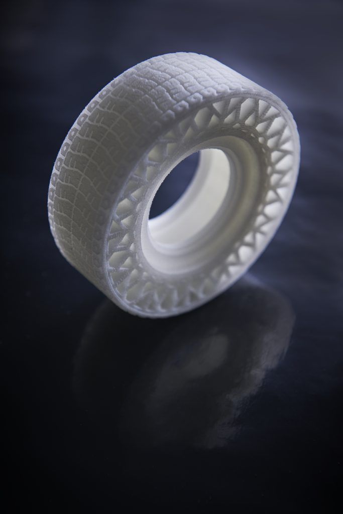 Most of the related experimental studies have been limited to analyze the mechanical properties of TMJs (Kang et al., 1998; Clason et al., 2004; Chen et al., 2016; Cota et al., 2019). The elastic modulus, failure strength, and energy absorption of the disc (Beek et al., 2001a; Kang et al., 2006) and the tensile, compressive, and failure strengths of the mandible (de Zee et al., 2007) were measured by the mechanical experiments of specimens of a human cadaver. In addition, animal experiments were used in the comparison of intraoral vertical ramus osteotomy and sagittal split ramus osteotomy (Zhao et al., 2007). These studies contributed to the mechanical understanding of the TMJ and provided theoretical supports to the simulation and clinics.
Temporomandibular joint-related experimental validations were reported in the previous studies (Gröning et al., 2009; Ramos et al., 2010; Merema et al., 2021). The mandibular geometry used in the FE models was validated by the cadaveric mandible (Ramos et al.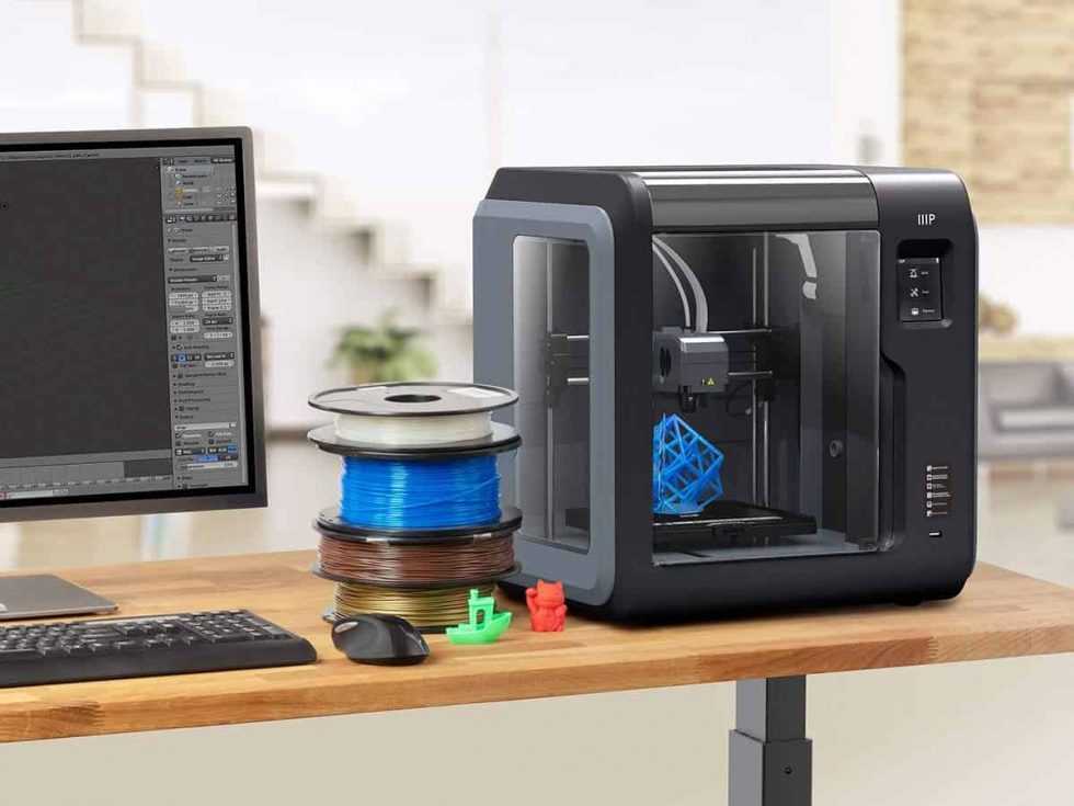 , 2017). The digital speckle pattern interferometry was conducted to measure the strains on the mandible, and it confirmed the accuracy of the simulation (Gröning et al., 2009). In addition, a polymeric replica of a human mandible was used to validate the FE models to design subsequent artificial TMJ (Ramos et al., 2010). However, these studies only focused on the mandible without the interaction in the TMJ, which was indispensable in investigating the biomechanics of TMJ. Because it was hard to characterize the internal structures and mechanical properties in mandible and maxilla, three-dimensional (3D) printing models with the high geometric and loading similarities of the individuals were used to validate the FE models. The material properties of the 3D printed model were close to those of the bony structures and assigned to the FE models. Thus, this study aimed to validate the maxillofacial FE models under the simulated central occlusion using the 3D printed experimental models.
Materials and Methods
Subjects and Data Acquisition
Five asymptomatic subjects (two female and three male, 29. 40 ± 8.32 years old) were identified and recruited by a single oral surgeon from the Affiliated Hospital of Stomatology, Chongqing Medical University, China. This study was approved by the institutional review board (IRB), all subjects have signed informed consents before the experiments, and the asymptomatic subjects chosen have no facial deformity and symptoms of temporomandibular disorder (TMD).
The complete head images were scanned by a cone-beam CT (CBCT) machine with slice thicknesses of 0.4 mm. All cross-sectional images were taken following a standardized protocol with 400 pixels × 400 pixels (0.4 mm pixel size).
Three-Dimensional Modeling
The CBCT data were transferred to the Digital Imaging and Communications in Medicine (DICOM) format and imported into the Materialise Interactive Medical Image Control System (MIMICS) 15.0 (Materialise, Leuven, Belgium) for model building. The 3D models including the mandible, maxilla, and teeth of all the subjects were constructed based on each slice of CBCT.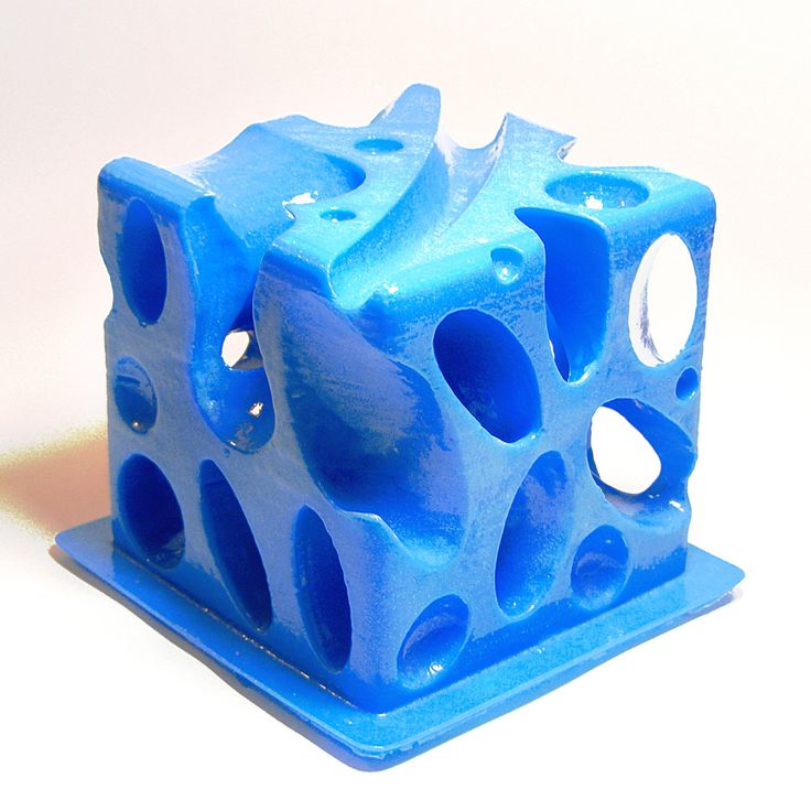 The articular discs were established according to the anatomical structure and the shape of constructed mandible and maxilla. The above structures of TMJs were saved as surface triangulation technique (STL) format and imported into ABAQUS 6.13 (Dassault SIMULIA, RI) for the generation of the 3D FE models of all the subjects (Figure 1).
Figure 1. The three-dimensional (3D) finite element (FE) model of temporomandibular joints (TMJs). (A) Front view, (B) lateral view, and (C) details in TMJ.
The STL files of the models were imported into the 3D printer, and then, the 3D experimental models were obtained (Figure 2). Polylactic acid (PLA) was selected for 3D printing from the bottom to the top due to its good mechanical strength, elastic modulus, thermoforming properties, and mechanical similarity with jawbones (Weng et al., 2000; Kong et al., 2005), because it is difficult to simulate the heterogeneous and orthotropic properties of bony structure without a cadaver.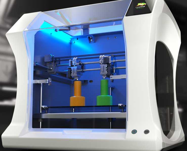 3D printing models with PLA were useful and were available for the validation of contact simulation in TMJ. The thickness of the printing layer was 0.2 mm with 100% filling, and the printing temperature was 210°C.
Figure 2. The distributions of 10 strain rosettes on the mandible: A located at the bilateral mandibular condyle necks, B located at the bilateral mandibular angles, and C, D, and E located at the bilateral mandibular bodies. R and L represented the right and left sides, respectively.
Mechanical Properties Test
Ten PLA 3D printed specimens based on the national standard were used to determine Young’s modulus and Poisson’s ratio. Since the mechanical properties of PLA after 3D printing would change, tensile tests of PLA 3D printed specimens should be carried out. According to the size of the specimens of national standard, the specimens for the tests were constructed. The STL files of the specimens were imported into the same 3D printer with the same conditions of TMJ models. Then, the tensile tests were performed on universal testing machine AG-IS (Shimadzu, Japan) and static strain gauge Dh4818 (Donghua, China), and Young’s modulus and Poisson’s ratio were 1.69 ± 0.14 GPa and 0.3 ± 0.05, respectively.
Simulated Central Occlusion Experiments
The 10 strain rosettes were distributed on the mandibular condyle necks, the mandibular angles, and the mandibular bodies of the experimental models (Figure 2). The monitoring regions were bilaterally arranged. The vertical pressure forces of 100 N, 150 N, 200 N, 250 N, and 300 N were applied to the experimental models for simulating central occlusion on the universal testing machine AG-IS (Figure 3). The magnitudes of these forces were derived from previous studies, and they were shifted to the top surface as a pressure force to conform to this occlusion (Lin et al., 2006; Shu and Liu, 2020). The constraint regions were marked to provide the simulated constraints.
Figure 3. The 3D experimental models of TMJs.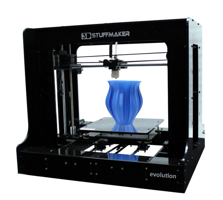
Finite Element Analysis
The bone and the discs were all modeled as linear elastic according to the experiments (Shu et al., 2019). The interactions of the disc-condyle, disc-temporal bone, and upper-lower dentition were considered as contact with a frictional coefficient of 0.001. The modified 10-node quadratic tetrahedron element (C3D10M) was used in the contact regions. The four-node linear tetrahedron element (C3D4) was used for the other regions of the models. The total number of elements for all the models was about 170,000. The loading and boundary conditions were identical with the 3D printed models in the experiments. The static solver was used to simulate the quasi-static status of the experiments.
Comparison and Statistical Analysis
For each model with the same load, the strains between the experimental and FE models were compared at each monitoring point. The difference was expressed as follows:
Difference=|Simulation-Experiment|Expriment×100%
Results
The differences between the simulated and experimental results were compared.![]() With the increase in loadings, the differences between simulated and experimental strains correspondingly increased. The maximum difference was 4.92% under the force of 300 N for one sample (Figure 4). The average strain difference between the simulation and the experiment of this sample under the force of 300 N was 2.43%, which was the maximum among the samples. The average differences of all the other samples were 1.46 and 2.30%. Under the other forces, the differences decreased to 1%.
With the increase in loadings, the differences between simulated and experimental strains correspondingly increased. The maximum difference was 4.92% under the force of 300 N for one sample (Figure 4). The average strain difference between the simulation and the experiment of this sample under the force of 300 N was 2.43%, which was the maximum among the samples. The average differences of all the other samples were 1.46 and 2.30%. Under the other forces, the differences decreased to 1%.
Figure 4. The experimental and simulated strains of the 10 monitoring points for a sample under the force of 300 N. ✩ represented the maximum difference between experimental and simulated strains. A located at the bilateral mandibular condyle necks, B located at the bilateral mandibular angles, and C, D, and E located at the bilateral mandibular bodies. 0 and 90 represented the horizontal and vertical directions, respectively. R and L represented the right and left sides, respectively.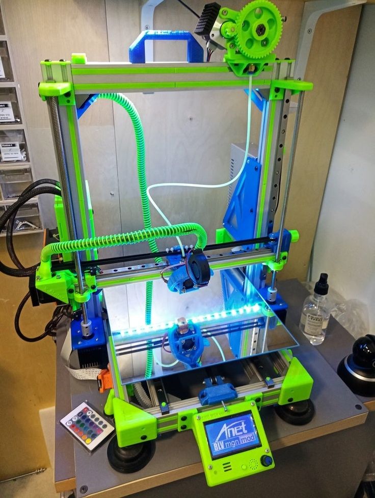
The magnitudes of all the strains increased with the increase in force (Figure 5). The vertical strains of each monitoring point were all expressed as compressive strains under all forces (Figure 5). However, the horizontal strains located at the bilateral condyle necks were always presented as tensile strains. It was complex at other positions in the horizontal directions due to the individual geometric differences.
Figure 5. The experimental horizontal (A) and vertical (B) strains of the 10 monitoring points with increased loads for a single sample. A located at the bilateral mandibular condyle necks, B located at the bilateral mandibular angles, and C, D, and E located at the bilateral mandibular bodies. 0 and 90 represented the horizontal and vertical directions, respectively. R and L represented the right and left sides, respectively.
The distributions of the strains on the mandible were different from each other (Figure 6). The strains, especially vertical strains, at the mandibular body close to the facial midline (i. e., monitoring point E) were generally greater than those at other locations. In addition, the strains on the mandibular ramus (monitoring point A) were slightly greater than those on the edges of the mandibular body (monitoring point C).
Figure 6. The simulated strains from FE models of all the five samples under the force of 300 N. A located at the bilateral mandibular condyle necks, B located at the bilateral mandibular angles, and C, D, and E located at the bilateral mandibular bodies. 0 and 90 represented the horizontal and vertical directions, respectively. R and L represented the right and left sides, respectively.
Discussion
Finite element analysis (FEA) was usually used in the study of oral biomechanics (Dicker et al., 2012; Qi et al., 2012; Liu et al., 2016; Demircan et al., 2020; Lai et al., 2020). Several interactions were considered in the simulation of TMJ (Liu et al., 2008). Contact was proven to be good in the simulation of complex interactions of maxillofacial models (Liu et al.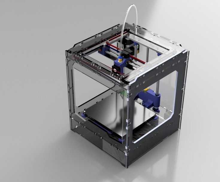 , 2008, 2016). However, there was no validation of the precision of contact to simulate the interactions in the TMJs. The cadaver models were not adopted due to the difficulty in determination of the heterogeneity of the geometry and internal bone characteristics. Thus, this study aimed to verify the precision of simulation using the experiments of 3D printing models.
The condition of the simulated models was the same as the experimental samples. 3D printed and FE models shared the same geometry based on the constructed models from medical images. The material properties of the FE models were from the mechanical properties test. Moreover, the loadings and the boundary conditions from the experiments were applied to the corresponding FE models. In addition, the simulated stress distribution of the disc was similar to the centric occlusions (Beek et al., 2000; Shu et al., 2019), with its high stress located at the lateral intermediate zone. The monitoring points for both groups were also the same. Thus, the experimental validation of the maxillofacial system was reliable.
Under the five different pressure forces, the maximum difference of all the samples between simulated and experimental results was 4.92% among all monitoring points (Figure 4). The maximum difference was located at the middle of the mandibular body of Sample 2 (Figure 6). It was clear that the changes in the forces did not affect the differences between experiments and simulations. Furthermore, the vertical strains always presented compressive strains with the increase in forces from 100 to 300 N. The magnitudes of all the strains tended to increase with the increase in forces (Figure 5). Therefore, contact was reasonable to simulate the contact of TMJ.
The rhythmicity of the strains with the positions was different from each other due to the differences in individual geometry of the maxilla and mandible (Figure 6). In general, monitoring point E showed the greatest horizontal and vertical strains. The results showed in mandibular bodies are the closer to the facial midline, the greater the strain.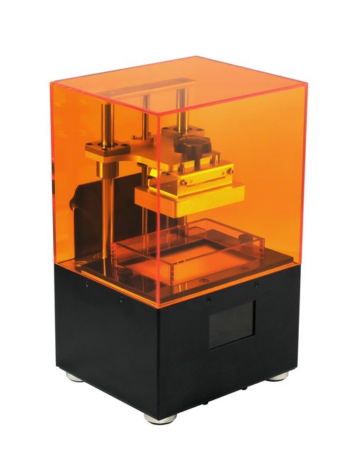 In the vertical direction, monitoring points A (mandibular condyle necks) and B (mandibular angles) presented greater strains compared to points C and D (mandibular bodies).
Three replicate experiments were performed on each sample with the same force. Low deviations were found in the measurements of three replicate experiments. The high repeatability of the experiments was reflected. However, on one hand, the experimental results were influenced by the experimental conditions (humidity and temperature) and instruments. On the other hand, the FE outcomes should be the only results under the same loading condition. Thus, the accurate FE models were more controllable and freer from environmental disturbances.
The combined 3D printing experiments and FEA could be further used in clinics. The biomechanical environment could be evaluated, and then, the individual treatment plan could be designed. It could be also applied in maxillofacial surgery, and the simulation of bilateral sagittal split ramus osteotomy (BSSRO) could be applied to the FE models to evaluate the postoperative biomechanical status of the patients. These postoperative outcomes could also help clinicians optimize surgical strategies and prevent postoperative complications. In addition, the validations of FE models of the TMJ ensured the biomechanical design of the prosthesis of TMJ. In the previous study, a human cadaver was used to validate the correction of condyle implants of humans (Mesnard and Ramos, 2016). In this study, 3D printing experiments could also provide more precious validation of FE models to improve the condylar implants in TMJ.
One major limitation of this study was that all the samples of this study were asymptomatic subjects. The models of patients should be reconstructed to provide further verification. Another limitation was that 3D printing models could not characterize the heterogeneity and orthotropy of human mandible, maxilla, and disc, like previous studies using FE models and cadaver experiments (Ichim et al., 2006; Ramos et al., 2010). However, FE models could be considered as heterogeneous and orthotropic and be proven as accurate within the allowable range of error.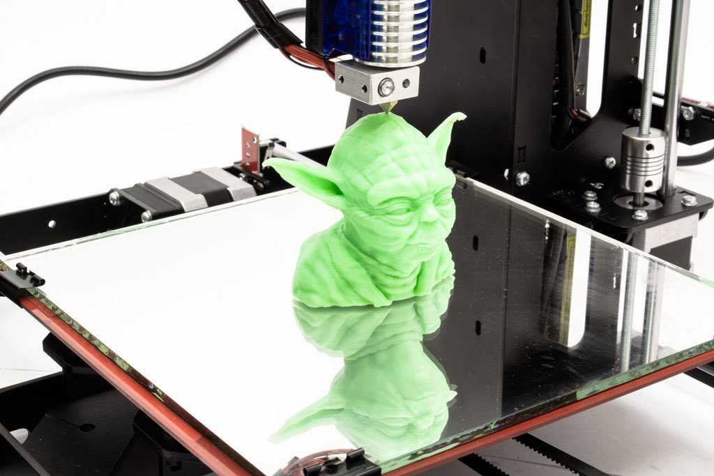 Furthermore, although the constraints were marked to ensure the consistency of experiments and simulations, there would be some errors in the constraint.
Conclusion
The vertical and horizontal strains between the experiments on 3D printed models and the FEA had less than 5% differences for all the samples. It proved that the FE models could provide strains within a minimum 95% agreement. Therefore, it was accurate to use contacts to simulate the interactions in TMJs in future research studies and applications.
Data Availability Statement
The original contributions presented in the study are included in the article/supplementary material, further inquiries can be directed to the corresponding author/s.
Ethics Statement
The studies involving human participants were reviewed and approved by Institutional Review Board (IRB) of the Affiliated Hospital o Stomatology, Chongqing Medical University. The patients/participants provided their written informed consent to participate in this study. Written informed consent was obtained from the individual(s) for the publication of any potentially identifiable images or data included in this article.
Author Contributions
JS provided the ideas, designed a complete research program, analyzed the data of 3D model and FEM model, and was responsible for drafting the manuscript. YZ and HL collected the experimental data and completed the simulation. HL carried the 3D printing experiment according to the CT image data. ZL got the support of the National Natural Science Foundation of China and the Government of Yibin and provided technical guidance for the whole research. All authors contributed to the article and approved the submitted version.
Funding
This study was supported by the National Natural Science Foundation of China under grant No. 31670963, the Strategic Cooperation Project between Sichuan University and Yibin Municipal People’s Government under grant No. 2019CDYB-16, and the Fundamental Research Funds for the Central Universities of China.
Conflict of Interest
The authors declare that the research was conducted in the absence of any commercial or financial relationships that could be construed as a potential conflict of interest.
References
Beek, M., Aarnts, M. P., Koolstra, J. H., Feilzer, A. J., and van Eijden, T. (2001a). Dynamic properties of the human temporomandibular joint disc. J. Dental Res. 80, 876–880. doi: 10.1177/00220345010800030601
PubMed Abstract | CrossRef Full Text | Google Scholar
Beek, M., Koolstra, J. H., van Ruijven, L. J., and van Eijden, T. M. G. J. (2000). Three-dimensional finite element analysis of the human temporomandibular joint disc. J. Biomech. 33, 307–316. doi: 10.1016/s0021-9290(99)00168-2
CrossRef Full Text | Google Scholar
Beek, M., Koolstra, J. H., van Ruijven, L. J., and van Eijden, T. M. G. J. (2001b). Three-dimensional finite element analysis of the cartilaginous structures in the human temporomadibular joint. J. Dental Res. 80, 1913–1918. doi: 10.1177/00220345010800101001
PubMed Abstract | CrossRef Full Text | Google Scholar
Chen, J., Akyuz, U., Xu, L., and Pidaparti, R. M. (1998). Stress analysis of the human temporomandibular joint. Med. Eng. Phys. 20, 565–572. doi: 10.1016/s1350-4533(98)00070-8
CrossRef Full Text | Google Scholar
Chen, J. N., Suenaga, H., Hogg, M., Li, W., Swain, M., and Li, Q. (2016). Determination of oral mucosal Poisson’s ratio and coefficient of friction from in-vivo contact pressure measurements. Comput. Methods Biomech. Biomed. Eng. 19, 357–365. doi: 10.1080/10255842.2015.1028925
PubMed Abstract | CrossRef Full Text | Google Scholar
Clason, C., Hinz, A. M., and Schieferstein, H. (2004). A method for material parameter determination for the human mandible based on simulation and experiment. Comput. Methods Biomech. Biomed. Eng. 7, 265–276. doi: 10.1080/10255840412331313590
PubMed Abstract | CrossRef Full Text | Google Scholar
Cota, J. M. G., Leale, D. M., Arzi, B., and Cissell, D. D. (2019). Regional and disease-related differences in properties of the equine temporomandibular joint disc. J. Biomech. 82, 54–61. doi: 10.1016/j.jbiomech.2018.10.017
PubMed Abstract | CrossRef Full Text | Google Scholar
de Zee, M., Dalstra, M., Cattaneo, P. M., Rasmussen, J., Svensson, P., and Melsen, B. (2007). Validation of a musculo-skeletal model of the mandible and its application to mandibular distraction osteogenesis. J. Biomech. 40, 1192–1201. doi: 10.1016/j.jbiomech.2006.06.024
PubMed Abstract | CrossRef Full Text | Google Scholar
Demircan, S., Ureturk, E. U., Apaydin, A., and Sen, S. (2020). Fixation methods for mandibular advancement and their effects on temporomandibular joint: a finite element analysis study. Biomed. Res. Int. 2020:8.
Google Scholar
DeVocht, J. W., Goel, V. K., Zeitler, D. L., and Lew, D. (2001). Experimental validation of a finite element model of the temporomandibular joint.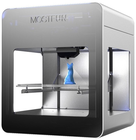 J. Ora Maxillofac. Surg. 59, 775–778. doi: 10.1053/joms.2001.24292
PubMed Abstract | CrossRef Full Text | Google Scholar
Dicker, G. J., Tuijt, M., Koolstra, J. H., Van Schijndel, R. A., Castelijns, J. A., and Tuinzing, D. B. (2012). Static and dynamic loading of mandibular condyles and their positional changes after bilateral sagittal split advancement osteotomies. Int. J. Oral maxillofac. Surg. 41, 1131–1136. doi: 10.1016/j.ijom.2012.03.013
PubMed Abstract | CrossRef Full Text | Google Scholar
Gregolin, R. F., Zavaglia, C. A. D., Tokimatsu, R. C., and Pereira, J. A. (2017). Biomechanical stress and strain analysis of mandibular human region from computed tomography to custom implant development. Adv. Mater. Sci. Eng. 2017:9.
Google Scholar
Gröning, F., Liu, J., Fagan, M. J., and O’Higgins, P. (2009). Validating a voxel-based finite element model of a human mandible using digital speckle pattern interferometry. J. Biomech. 42, 1224–1229.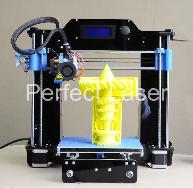 doi: 10.1016/j.jbiomech.2009.03.025
PubMed Abstract | CrossRef Full Text | Google Scholar
Ichim, I., Swain, M., and Kieser, J. A. (2006). Mandibular biomechanics and development of the human chin. J. Dental Res. 85, 638–642. doi: 10.1177/154405910608500711
PubMed Abstract | CrossRef Full Text | Google Scholar
Kang, H., Bao, G. J., and Qi, S. N. (2006). Biomechanical responses of human temporomandibular joint disc under tension and compression. Int. J. Oral Maxillofac. Surg. 35, 817–821. doi: 10.1016/j.ijom.2006.03.005
PubMed Abstract | CrossRef Full Text | Google Scholar
Kang, H., Yi, X. Z., and Chen, M. S. (1998). A study of tensile mechanical property of human temporomandibular joint disc. West China J. Stomatol. 16, 253–255.
Google Scholar
Kong, H., Pan, K. F., and Zhang, S. J. (2005). The study of the new modified copolymer of PLA and PEG on the repair of rabbit mandibular defect. J. Oral Maxillofac. Surg. 15, 24–28.
Google Scholar
Lai, L. F., Huang, C. Y., Zhou, F., Xia, F. J., and Xiong, G. F. (2020). Finite elements analysis of the temporomandibular joint disc in patients with intra-articular disorders. BMC Oral Health 20:8. doi: 10.1186/s12903-020-01074-x
PubMed Abstract | CrossRef Full Text | Google Scholar
Lin, C. L., Wang, J. C., and Kuo, Y. C. (2006). Numerical simulation on the biomechanical interactions of tooth/implant-supported system under various occlusal forces with rigid/non-rigid connections. J. Biomech. 39, 453–463. doi: 10.1016/j.jbiomech.2004.12.020
PubMed Abstract | CrossRef Full Text | Google Scholar
Liu, Z., Fan, Y., and Qian, Y. (2008). Comparative evaluation on three-dimensional finite element models of the temporomandibular joint. Clin. Biomech. 23 Suppl 1, S53–S58.
Google Scholar
Liu, Z., Qian, Y. L., Zhang, Y. L., and Fan, Y. B. (2016). Effects of several temporomandibular disorders on the stress distributions of temporomandibular joint: a finite element analysis.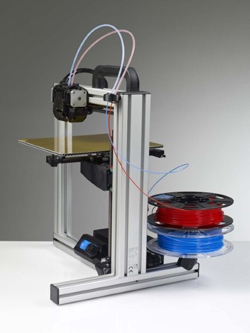 Comput. Methods Biomech. Biomed. Eng. 19, 137–143. doi: 10.1080/10255842.2014.996876
PubMed Abstract | CrossRef Full Text | Google Scholar
Mahdian, N., Dostalova, T. J., Danek, J., Nedoma, J., Kohout, J., Hubacek, M., et al. (2013). 3D reconstruction of TMJ after resection of the cyst and the stress-strain analyses. Comput. Methods Programs Biomed. 110, 279–289. doi: 10.1016/j.cmpb.2012.12.001
PubMed Abstract | CrossRef Full Text | Google Scholar
Merema, B. B. J., Kraeima, J., Glas, H. H., Spijkervet, F. K. L., and Witjes, M. J. H. (2021). Patient-specific finite element models of the human mandible: lack of consensus on current set-ups. Oral Dis. 27, 42–51. doi: 10.1111/odi.13381
PubMed Abstract | CrossRef Full Text | Google Scholar
Mesnard, M., and Ramos, A. (2016). Experimental and numerical predictions of Biomet((R)) alloplastic implant in a cadaveric mandibular ramus. J. Craniomaxillofac. surg. 44, 608–615. doi: 10.1016/j.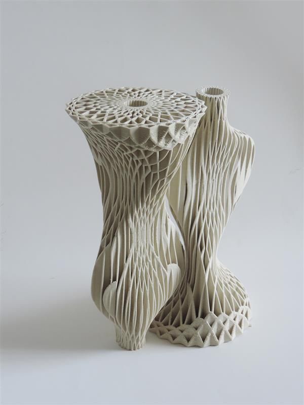 jcms.2016.02.004
PubMed Abstract | CrossRef Full Text | Google Scholar
Poluha, R. L., Canales, G. T., Costa, Y. M., Grossmann, E., Bonjardim, L. R., and Conti, P. C. R. (2019). Temporomandibular joint disc displacement with reduction: a review of mechanisms and clinical presentation. J. Appl. Oral Sci. 27:e20180433.
Google Scholar
Qi, X. D., Ma, L. M., and Zhong, S. Z. (2012). The influence of the closing and opening muscle groups of jaw condyle biomechanics after mandible bilateral sagittal split ramus osteotomy. J. Craniomaxillofac. Surg. 40, e159–e164.
Google Scholar
Ramos, A., Ballu, A., Mesnard, M., Talaia, P., and Simões, J. A. (2010). Numerical and experimental models of the mandible. Exp. Mech. 51, 1053–1059. doi: 10.1007/s11340-010-9403-x
CrossRef Full Text | Google Scholar
Ramos, A., Nyashin, Y., and Mesnard, M. (2017). Influences of geometrical and mechanical properties of bone tissues in mandible behaviour - experimental and numerical predictions.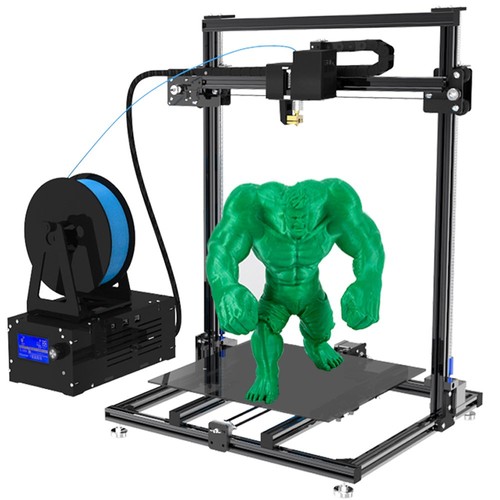 Comput. Methods Biomech. Biomed. Eng. 20, 1004–1014. doi: 10.1080/10255842.2017.1322072
PubMed Abstract | CrossRef Full Text | Google Scholar
Shu, J., and Liu, Z. (2020). The Biomechanical comparisons of different periodontal conditions under the different extracoronal precision attachment restorations for the mandibular kennedy i dentition defect. J. Mech. Med. Biol. 20:2050019. doi: 10.1142/s0219519420500190
CrossRef Full Text | Google Scholar
Shu, J., Ma, H., Jia, L., Fang, H., Chong, D. Y. R., Zheng, T., et al. (2020a). Biomechanical behaviour of temporomandibular joints during opening and closing of the mouth: a 3D finite element analysis. Int. J. Numer. Methods Biomed. Eng. 36:e3373.
Google Scholar
Shu, J., Teng, H., Shao, B., Zheng, T., Liu, Y., and Liu, Z. (2020b). Biomechanical responses of temporomandibular joints during the lateral protrusions: a 3D finite element study. Comput. Methods Programs Biomed. 195:105671.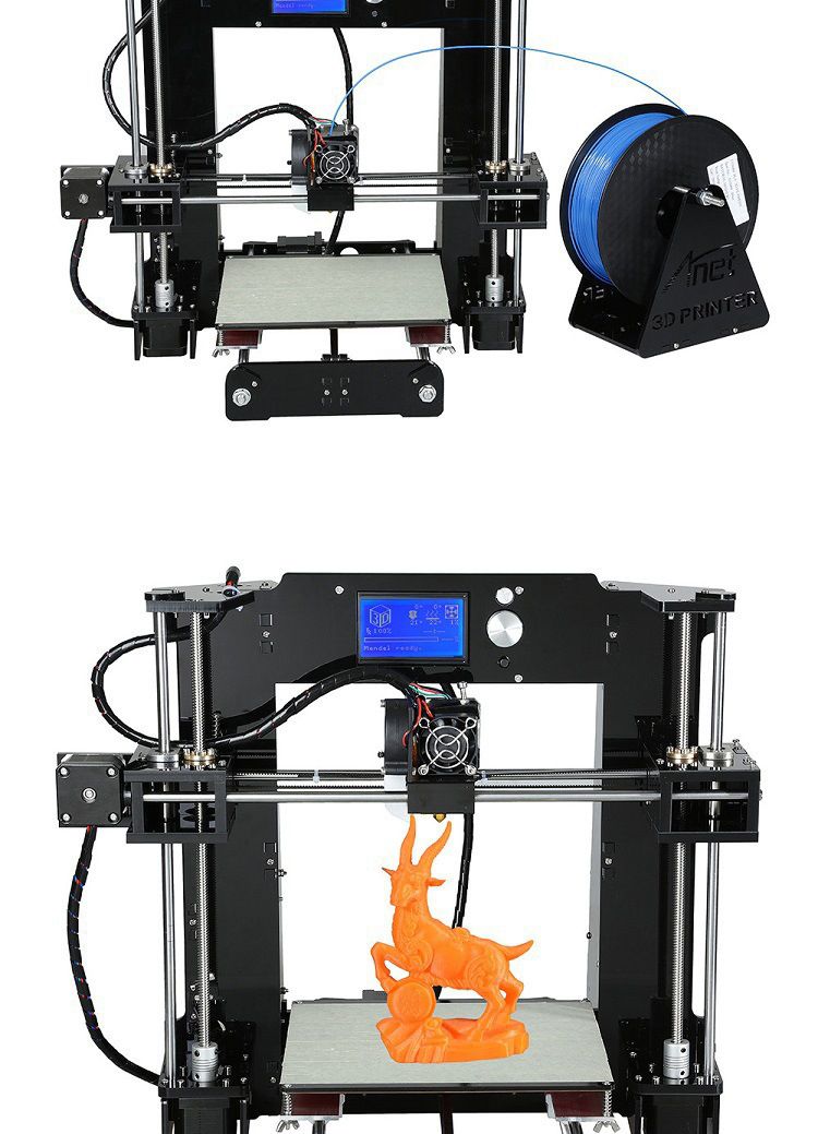 doi: 10.1016/j.cmpb.2020.105671
PubMed Abstract | CrossRef Full Text | Google Scholar
Shu, J., Zhang, Y., and Liu, Z. (2019). Biomechanical comparison of temporomandibular joints after orthognathic surgery before and after design optimization. Med. Eng. Phys. 68, 11–16. doi: 10.1016/j.medengphy.2019.03.018
PubMed Abstract | CrossRef Full Text | Google Scholar
Sun, M. X., Yang, J. J., Zhou, R. Z., Li, N. Y., Xia, J. N., and Gu, F. (2015). Mechanical analysis on individualized finite element of temporal-mandibular joint under overlarge jaw opening status. Int. J. Clin. Exp. Med. 8, 9046–9054.
Google Scholar
Tanaka, E., and van Eijden, T. (2003). Biomechanical behavior of the temporomandibular joint disc. Crit. Rev. Oral Biol. Med. 14, 138–150. doi: 10.1177/154411130301400207
PubMed Abstract | CrossRef Full Text | Google Scholar
Weng, Y. L., Cao, Y. L., and Vacanti, C. A. (2000). The experimental study of tissue engineered mandible condyle in the shape of human. Shanghai J. Stomatol. 9, 94–96.
Google Scholar
Zhao, Q., Hu, J., Wang, D., and Zhu, S. (2007). Changes in the temporomandibular joint after mandibular setback surgery in monkeys: intraoral vertical versus sagittal split ramus osteotomy. Oral Surg. Oral Med. Oral Pathol. Oral Radiol. Endod. 104, 329–337. doi: 10.1016/j.tripleo.2006.12.024
PubMed Abstract | CrossRef Full Text | Google Scholar
What is 3D printing and how it can be used! Interesting!
What is 3D printing
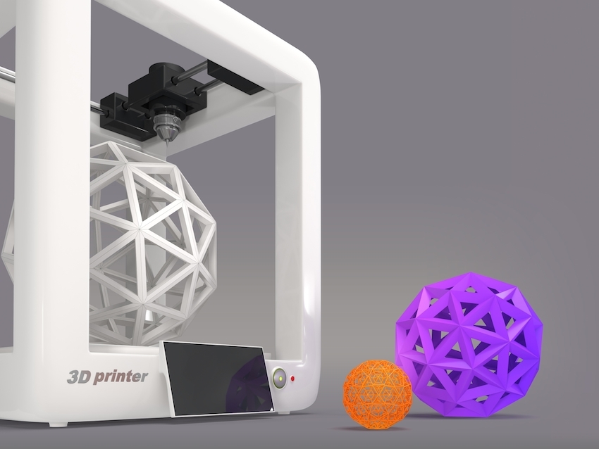
3D printing technology was patented in the 80s of the last century, but gained popularity relatively recently. New, promising techniques have been developed and the possibilities of 3D technologies have reached a completely new level. However, to this day, the technique is not known in all circles, and not everyone is aware of what 3D printing is. In today's article, we will try to explain in detail and in an accessible way what 3D printing is and where it is used.
In short, 3D printing is a technique for manufacturing three-dimensional products based on digital models. Regardless of the specific technology, the essence of the process is the gradual layer-by-layer reproduction of objects.
This process uses a special device - a 3D printer, which prints certain types of materials. More details about it are written here. Other names for the technology are rapid prototyping or additive manufacturing. Often the phrase "additive technologies" is used in the meaning of "3D technologies".
3D printing steps
To make it clearer what 3D printing is, let's take a look at the playback process step by step. Below are the specific stages of 3D printing. How it works:
- 3D modeling of the required object is performed according to certain rules;
- The file with the digital model is loaded into the slicer program, which generates the control code for the 3D printer;
- Sets required 3D printing options;
- The code is written to a removable memory that connects to the 3D printer;
- 3D model reproduced.
Objects are reproduced gradually. According to the required shape, the selected material is applied layer by layer, forming the finished product. It is worth noting that the possibilities of 3D printing are almost limitless, that is, anything can be made. In some technologies, very thin overhanging elements are provided with supports, thanks to which they can be avoided from sagging.
Naturally, this is a very simplified description of the stages of 3D printing, but they give a very clear idea of the essence of the technique.
Other questions and answers about 3D printers and 3D printing:
- Basics What is 3D scanning?
- Basics What is a 3D model?
3D Printing Technologies
Different 3D printing technologies are used to reproduce different objects. They differ both in the consumables used, and in the speed and accuracy of printing. Here are the main 3D printing technologies:
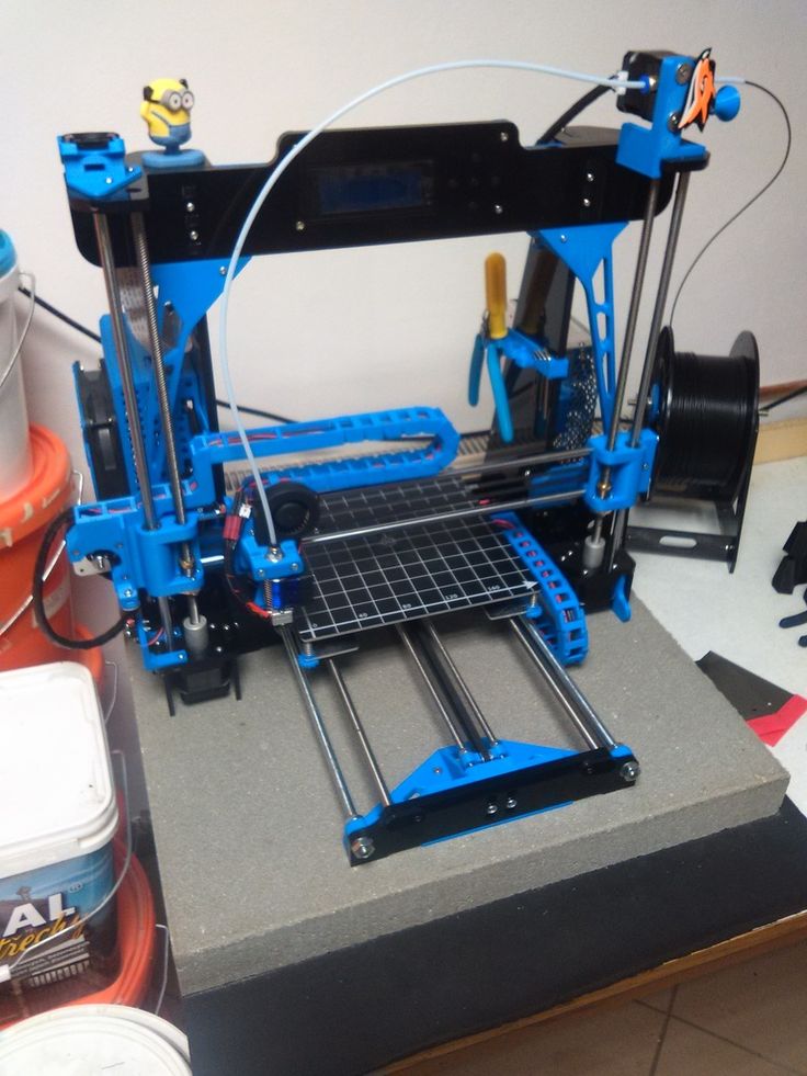
- Fused deposition modeling (FDM) .
 One of the most common 3D printing technologies, used in most desktop 3D printers, and represents an ideal price / quality ratio. Printing occurs by layer-by-layer supply of a thread of molten plastic;
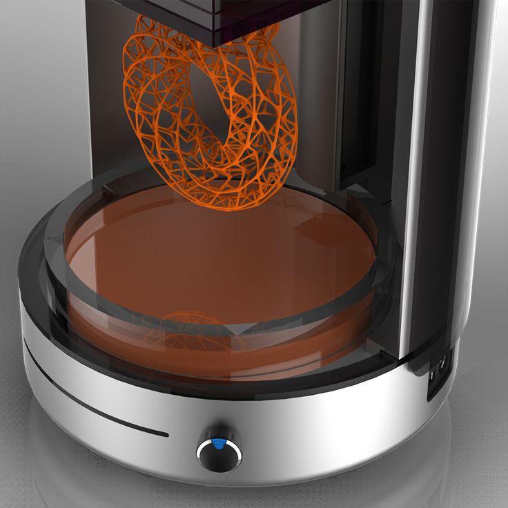
 - Laser stereolithography (SLA) . The formation of the object occurs due to the layer-by-layer illumination of a liquid photopolymer resin by a laser, which hardens under the influence of radiation. One of the variations of this technology is DLP 3D printing. It uses a special projector instead of a laser. Both 3D printing methods are used to create objects with a high degree of detail. In the case of DLP printing, speed is also an added advantage;
- Selective laser sintering (SLS) . Reproduction is performed by layer-by-layer melting of a special powder under the action of laser radiation. This 3D printing method is widely used in the industry for the manufacture of durable metal elements
3D Printing Applications
As you may have guessed by now, 3D printing is extremely versatile.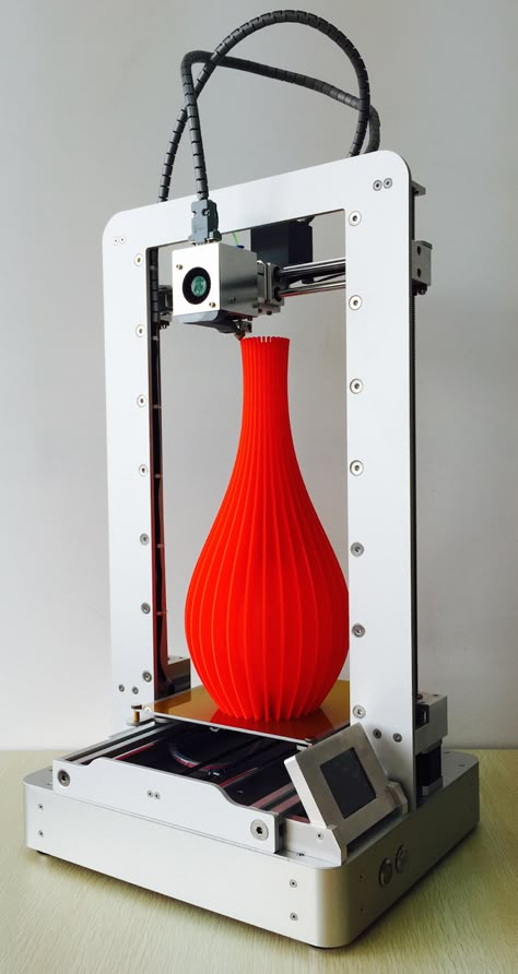 The second name of the technology - rapid prototyping - speaks for itself. In the manufacture of prototypes and models of models, 3D printing can be simply indispensable. It is also a very cost-effective solution for small-scale production. In the aerospace and automotive industries, 3D technologies are already being used with might and main due to the high profitability and speed of manufacturing components. Culinary professionals are working on the development of 3D food printers, and in medicine, 3D printing has become something of a technology of the future. With the help of 3D bioprinting, it is planned to produce bones, organs and living tissues, but for now, implants and full-fledged medicines are printed on 3D printers. Desktop 3D printers can be used for domestic purposes: for repairs, making various household items, and so on. And designers, fashion designers, sculptors and artists appreciate the possibilities of 3D printing and 3D modeling as an unusual way to realize their talent.
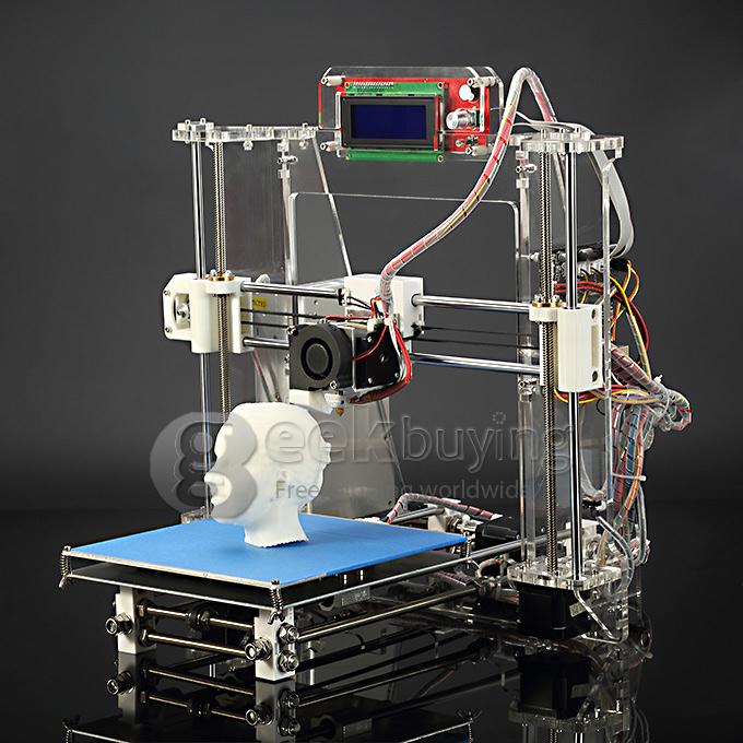
Well, that was a brief description of what 3D printing is. We hope we were able to provide the necessary information in an accessible way. If you have additional questions that we have not covered, write to us by e-mail and we, if necessary, will add your questions! Best regards, 3DDevice team.
We also want to remind you about the possibility to order 3D printing, 3D scanning, 3D modeling services or purchase of related equipment and consumables with delivery throughout Ukraine in 3DDevice. If you have any questions, please contact us at one of the phone numbers listed here. We look forward to collaborating!
Return to the main
90,000 company Desktop Metal has released a 3D printer for working withWood
Subscribe to
Subscribe
I do not want
11
This is earlier in cases of reciprocating the flights of the Asters and the unless children had to plan cabbage from logs, and now you can use additive technologies. Let's talk about progress.
Let's start with a little background. Last May, Desktop Metal announced a new process called Forust that allows wood to be printed. Well, like new: this is a variation on the theme of inkjet-powder 3D printing or Binder Jetting, where a binder material is sprayed onto layers of small particles that form the contours of products. Variants of this technology are widely used for 3D printing with polymers, gypsum, and even metals – in the latter case, blanks are grown from powders for subsequent sintering into all-metal products. In other words, the choice of compatible materials is very wide, and now it comes to wood.
To be more precise, the consumables are production waste from woodworking enterprises. The developers' logic is simple: if you want to help save nature, don't throw away shavings and sawdust. In a new version of the technology, the chopped wood is bound by a sprayed epoxy bio-resin, and the output is something like fiberboard, only of an arbitrary shape.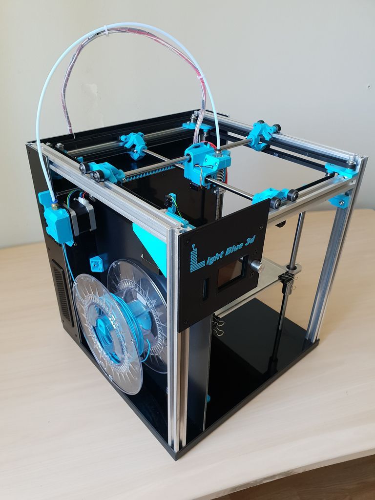
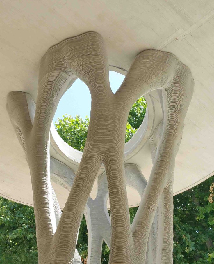
This is exactly where the advantages of 3D printing come into play - you can grow almost any squiggle, including those that are too complex for milling, and even with the parallel processing of waste instead of additional deforestation. The technology allows you to imitate different types of wood, the resulting products lend themselves well to grinding, are durable, pleasant to the eye and touch, and even smell like wood.
Initially, Desktop Metal did not deal with inkjet-powder 3D printing, but recently it has been aggressively crushing well-known brands, including the German company EnvisionTEC and the German-American ExOne. EnvisionTEC is known primarily for professional stereolithographic 3D printers, but in 2017, together with Viridis3D, it piloted a robotic additive system for inkjet-powder 3D printing of foundry tooling with sand mixtures. ExOne is generally considered one of the leaders in the field of Binder Jetting, although it specializes in systems for working with metal powders.
These companies were bought out by Desktop Metal for a reason: the fledgling Massachusetts company is simultaneously eliminating competition and leveraging the expertise of its subsidiaries to perfect its own branded blasting systems, such as the Desktop Metal Shop pictured above. So it was adapted for 3D printing with wood, and at the same time renamed the Shop System Forust Edition, adding a green strip to the front panel - because ecology, “green” technologies, and all that. 93/hr or 21 mm/hr on the Z-axis. Mainly maple and oak waste from sawmills is used, and the binder is an eco-friendly lignin-based epoxy, either colorless or brown. This combination of materials makes it possible to reproduce different shades and textures that imitate ash, mahogany and other varieties. The processing of 3D printed products is basically the same as the processing of natural wood: you can drill, sand, impregnate, varnish, and so on.
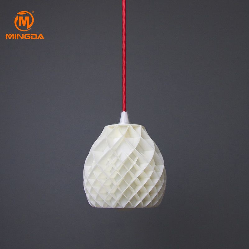
Some products with the new technology can already be found on the commercial market, such as the decorative Cocoon lights in the illustration above.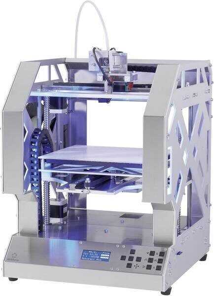 Another interesting project is a guitar by Oakland University additive manufacturing professor and 3D printed musical instrument enthusiast Olaf Diegel ( in the illustration below ).
In general, if someone needs to solve the problem of the demographic crisis using the latest digital manufacturing technologies, ask for suggestions on the Forust project website. On November 15-18, the technology will be available at the Formnext 2022 trade show in Frankfurt am Main.
Do you have interesting news? Share your developments with us, and we will tell the whole world about them! We are waiting for your ideas at [email protected].
More interesting articles
ten
Subscribe to the author
Subscribe
Don't want
On October 21, the solemn opening of the production site for the production of so-called.