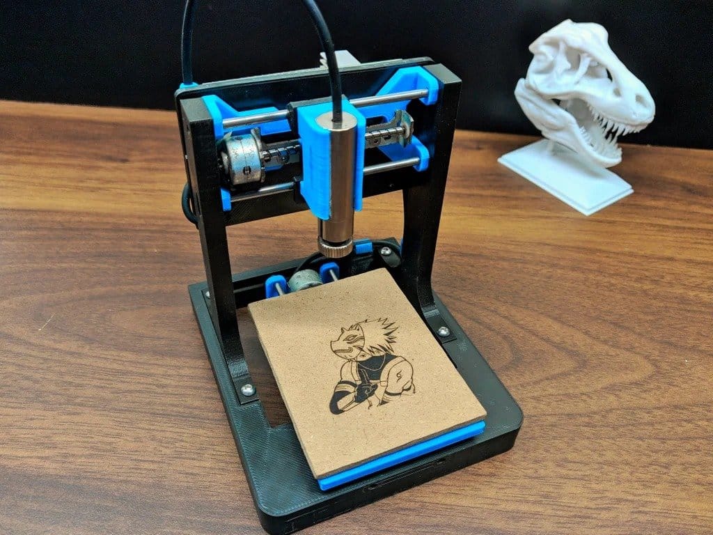
Dvd 3d printer
How to make 3D Printer at home
3D Printer is a Computerized Numerical Control(CNC) machine which can run through G-code.
G-code is a programming language for CNC that instructs machines where and how to move.
Making of DVD drive 3D printer
Required Materials-
Arduino Mega
SMPS
Extruder
Nema17
Hotend
Slider
DVD Slider
Note-
*HOT-END 1.75mm Direct Filament Wade Extruder 0. 4mm Nozzle
*SMPS should be 12V @ 5amps
STEP-1
First of all you need two Standard PC OLD DVD DRIVE, The DVD drive must has 4 wire stepper motor(you can’t do this with normal DVD drive which has two wire DC motor).
Now Unscrew the DVD drive and pick out the lens mechanism.
Now you need to check the stepper motor is working or not, it’s an easy method , mainly stepper motor has two coils and one coil has two ends so respectively two wire has four ends so the upper side of stepper motor has 4 connection point and it connects to the two coils internally. Now you have to point out your A1B1A2B2 connections by following this image.
Now you need to take your multi-meter in continuity point and check 4 wire point if stepper motor coil is in good condition then the multi-meter will buzzing two wires.
Add END-STOP button on the X and Y axes
STEP-2
Now you need 25x25x1cm MDF Base and place a cooling fan for reduce the stepper motor heat, Two wooden cutting for X-axis placement.
After X-axis placement must place the Y-axis at 90 degree over the X-axis, you can add some super glue to produce better printing quality.
STEP-3
Preparing BED
You need 2mm black and transparent acrylic sheet to prepare appropriate bed, cut the acrylic sheet by 10x10cm and make 4 holes for screw, now insert screws using little spring(you can use pen refill spring), later you can align the bed using this screw, Now you can place your bed on the Y-axis, now your bed is ready.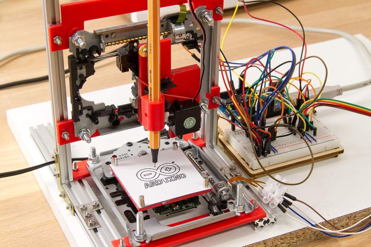
STEP-4
Preparing Z-axis
You need two pieces of 80mm Stepper motor slider for smooth Z-axis,
Place your slider parallel on the wood and screw it, now fit your wooden mount for hot-end,
now you need to fit your hot-end,Cooling Fan and PTFE Tube by following this image
Now you have to place your Z-axis by following Y-Axis and screw it and you 3D printer is almost ready.
STEP-5
Making Connections
You need
Arduino Mega
RAMPS V1.4
4X a4988 Driver
12V@5amps Power Supply
Make connections by following this Circuit Diagram
Now Connect your Extruder and Set the Z-axis END-Stop button and your are ready to Go.
STEP-6
Make Alignment
Align your bed by rotate crew clockwise or counter clockwise and give space between hot-end tip and bed about 0.5mm to 1mm.
WARNING – Don’t forget to align the bed, Because you will face trouble with printing.
Insert the 1.75mm PLA Filament
STEP-7
Programming
Upload Hex file through X-Loader
You must select this options-
Device- Mega(ATMEGA2560)
COM port- Available port
Baud rate- 115200
DOWNLOAD X-LOADER
HEX FILE
Now upload the code.
STEP-8
Run the Machine
You can use Pronterface to run the machine using of g-code and You have to convert the stl(3D File) file to g-code through slicer (I am using Ultimaker Cura).
Open Pronterface and Choose com port
choose baud rate 250000 and click connect,
after connection select g-code file,
You must set your hotend temperature about 185 degrees to melt the PLA filament.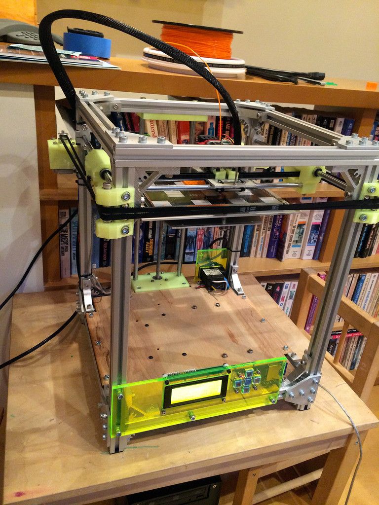
Fan control
Turning fans on and off is easy assuming you have them wired to D9 on RAMPS.
Button text: Fan on
Command:M106
Button text:Fan off
Command:M107
Button text:Fan 50%
Command:M106 S127
Select print an enjoy the printing
Congratulations you have made an awesome project..
Thank you so much for visiting…
DONATE
CONTACT US
e waste - Is a 3-D printer made from 3 CD Drives practically somewhat decent, being DIY and less expensive?
I would guess that a printer made in the following way would be both poor quality, and annoyingly frustrating, as well as requiring constant tinkering/re-adjustment. Also, if the chassis of the CD/DVD drive is incorporated into the design (as below) then the print volume is rather small, given the inherent limited movement of a CD/DVD mechanism.
If the steppers are used without the CD/DVD chassis then it might be possible to increase the print volume but then you would need to spend extra on the rods and support structure for the X gantry, the Y-axis print bed, and the Z-axis movement. If you do that, then the steppers from the CD/DVD drive probably would not have sufficient torque to move the additional weight - by incorporating the CD/DVD chassis the inertia of the movement has been kept to an acceptable minimum.
By using the CD/DVD drive's stepper motors you are only really saving the cost of buying three or four actual, more powerful and useful, stepper motors (as well as the cost of the additional rods and support).
That said, it could be quite amusing to make, and show off, and also provide some satisfaction if you do manage to print a tiny frog, parts for another printer, or whatever, with it. However, I wouldn't expect it to print anything to any great accuracy/tolerance/precision/etc., but it would maybe give you something unusual to talk about at dinner parties.
An example
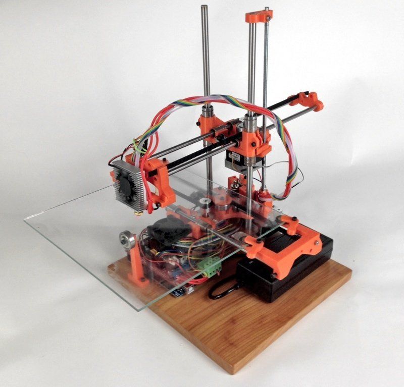
There is this (IMHO unjustifiably1) popular (i.e. well linked-to) Instructables guide: EWaste 60$ 3DPrinter, which describes making a 3D printer from old desktop computer parts2.
According to E-waste printer looks nice, prints really, really small, it has an awesome print volume of 37 mm x 37 mm x 18 mm.
Apparently, all you need is to salvage:
- 2 DVD drives (Matsushita stepper datasheet)
- 1 floppy disk drive (ensure it has steppers and not simple d.c. motors)
- 1 PC power supply
Then purchase these standard 3D printing components:
- RAMPS & Arduino Mega or RepRap Gen6/7 - Capable of running Marlin/Sprinter frimware
- Nema 17 stepper motor for the extruder - Either this, or better still something from RepRap Wiki - Nema 17, i.e. Kysan 1124090/42BYGh5803, Rattm 17HS8401, or Wantai 42BYGHW609.
- MK7/MK8-type direct drive gear for extruder
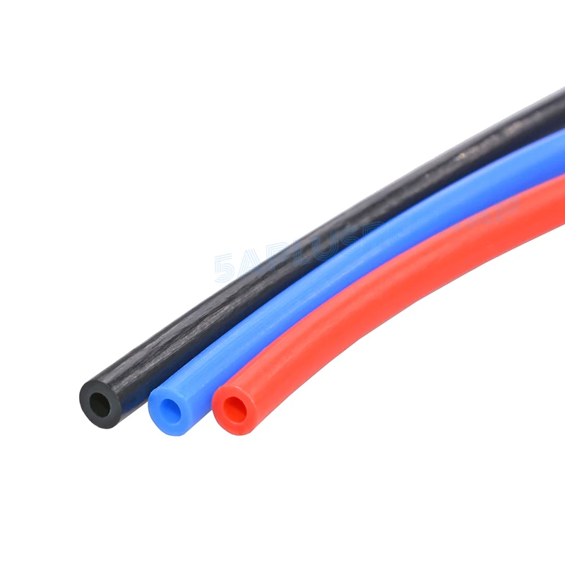
- PTFE tubing
- Hotend (throat, heaterblock, nozzle)
- Heater
- Thermistor
- Cables, female connectors, heat-shrink tube.
To make the frame, you need a 325 mm x 362 mm, 5 mm thick acrylic sheet, and use this template (missing files):
or this one (cnc-calisma-yalniz.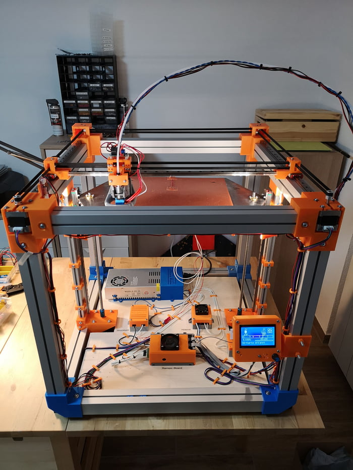 dwg):
dwg):
You will also need to 3D print these parts (the links to which have died):
- Extruder idle
- Extruder body
- Hot end holder
Once you've gathered all of the parts required, you can then try to work through the incomplete assembly steps of the Instructables guide.
Other links
- A very similar printer also made from an old DVD drive, Instructables: Curiosity 80\$ EWaste Educational 3D Printer. See also An E-waste 3D printer for every child?
- A very complete, and IMHO, a much more doable E-waste printer, Instructables: Complete Newbie Step by Step, 3D Printer With All Parts Lists
- Other Instructables, that I've not really looked into:
- Super Cheap 3D Printer From CD-Rom Drives
- Cherry- 60€ 3D-Printer
- Poor Man's 3D Printer
- Chimera: \$60 DLP High-Res 3D Printer
- 3d Printer for Less Than \$100 USD!!!
- A Low Cost 3D Printer With Basic Tools
- Thingiverse: \$65 3D printer made from recycled electronic waste
Footnotes
1 Most, if not all, of the links for the printer above are dead (this variant, mentioned above in Other links, is much more complete).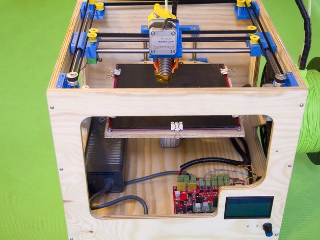 However, with a bit of knowledge, and common sense, it should be possible to work through those omissions:
- Marlin software - easy enough to find on Github
- The frame laser cut - the original file is missing but an alternative is still available
- The 3D printed parts for the extruder - as the links have died, you'll either need to find reasonable facsimiles on Thingiverse, which shouldn't be too hard to find, or buy them from cheap Chinese suppliers:
- Extruder idle
- Extruder body
- Hot end holder
2 Funnily enough, whilst searching around looking for information to fill in the gaps in the above answer, I found this question on 3DP.SE: Missing print steps in e-waste 3d printer
from cd rom (from disk drives) do-it-yourself
Recently, three-dimensional printing on printers has become very popular, but the equipment is expensive. Not everyone can afford such a luxury. A simple 3D printer from DVD drives can be assembled by hand, it will cost quite cheaply.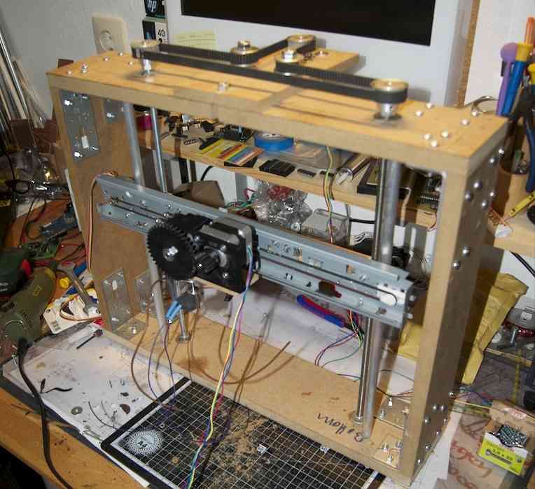 At the same time, it will allow you to print a variety of plastic parts at home.
What do you need to assemble?
Parts for a homemade 3D printer can be found in an old computer - CB/DVD drives. Some items will have to be bought, but their cost is not very high. For assembly you will need:
- DVD drives - 3 pcs.
- SUNFOUNDER Mega 2560 R3 ATmega2560-16AU controller with Arduino — 1 pc. It's better to buy it. The price does not exceed $10–12.
- Driver for motors Hobbypower A49988 for Reprap 3D printer — 4 pcs.
- Stepper motor STEPPERONLINE Nema 17 for DIY CNC 3D printer — 1 pc. Its cost with wires for connection is about $12–14.
- QWORK extruder module — 1 pc. Cost - 8–9USD
- Power supply with parameters: 12 V, 5A.
- Cables, wires and connectors for connection.
Prepare assembly tools and measuring instruments in advance: an electric drill, a hacksaw, a jigsaw, a soldering iron, pliers, wire cutters, a set of screwdrivers, a tester, a level, a ruler, a caliper.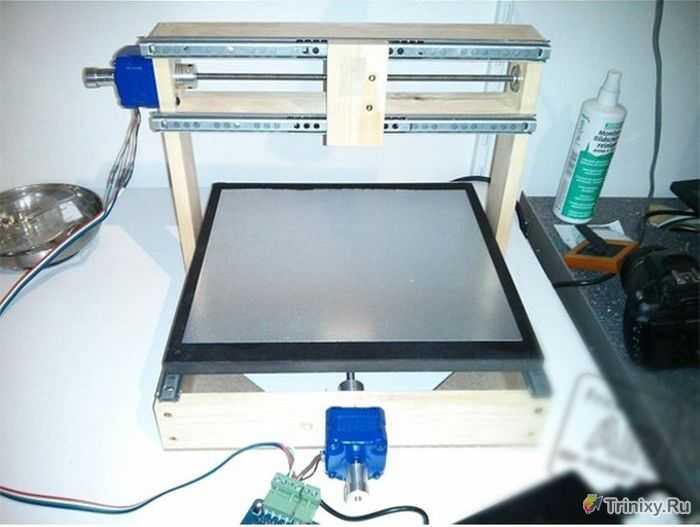
Step-by-step assembly instructions
A sheet of plywood or PCB 18–20 mm thick can be used as a base for the printer. It cuts to the right size. The base is marked. Holes are drilled for attaching load-bearing structural elements. Assembly is conditionally divided into several main stages.
X, Y, Z axes
Assembling the printer begins with mounting the machine frame in the form of vertical posts made of wood or aluminum profile. They are fixed on the base. Further, the Z axis is formed from one DVD input (photo 1). The plate is set vertically. For the Y-axis, the input is pinned sideways. A similar DVD drive is attached to this input for movement along the X axis. The result is a system (photo 2) that allows you to move the extruder head in two directions parallel to the base and in the vertical direction, changing the gap between the nozzle and the working surface.
The "brain" part, consisting of Arduino Uno, CNC Shield, A49988 drivers and other drive controls, is fixed on the back wall of the input. They are connected. An extruder module is mounted on the Z axis. A Nema 17 stepper motor is fixed above the extruder, which should ensure the supply of plastic (filament). It is better to connect it through a gearbox assembled from standard gears for a 3D printer.
Power supply
The next step is to install the drive power supply. It is important to connect it so that direct power is provided to the switch on the stand. Two wires of the block (12 V and GND) are used to power the controller. As a power supply, any block for a computer is suitable, for example, from a 20pin PC.
Checking engines
Engines can be prepared for operation in new conditions using special programs. In particular, the Arduino version 23 is quite suitable. After installing it, a program for flashing motors is downloaded. You can choose Marlin. The computer is connected to the CNC controller using a USB cable. Then the desired serial portal is selected under the Arduino IDE tools.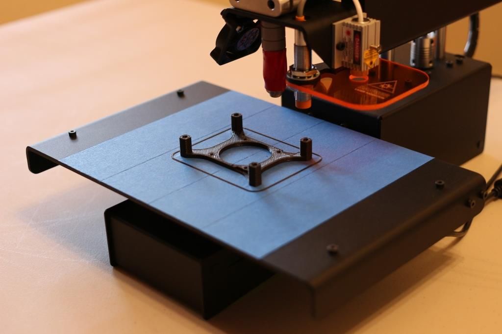 The firmware opens, after which the configuration parameters are displayed: #define MOTHERBOARD 3, Thermistor 7 and PID, and step 9per unit to set the controller.
PC Control Setup
Software needs to be installed to control the printer. One of the simplest and most reliable programs is Repetier Host. With the help of a slicer, sections of an object are associated with layers and a printer G-code is generated. Slices are adjusted by layer height, print speed and other parameters. Slicer configurations such as Skeinforge or Slic3r can be used.
Power control
The next step is to test the motors to adjust for current and intensity. The software starts and coordinates with the controller. Then you can switch to manual control of the engines. First of all, the maximum value of the current strength is set, at which they will not heat up. Adjustment is carried out on each axis separately. For measurements, a multimeter is used, installed in amplifier mode.
The computer is connected again and the current rise corresponding to the motor step is checked. With the help of a portable potentiometer, the values of the current limits for each axis are set. The current limits are: for the board - 80 mA, for steppers of the X and Y axes - 200 mA, for the Z axis - 400 mA. The extruder is also set to a current limit of about 400 mA.
Building the structure
It is important in the design of the printer to ensure that the frame and rails are strong and functional. They are the most important building blocks. They can be printed on a 3D printer using templates or cut using lasers using Auto Cad software from an acrylic plate with a thickness of about 5 mm. This technology ensures the creation of a structure without glue and screw connections.
Axle Calibration
The downloaded Marlin software is capable of standard axle calibration. More accurate programs for a homemade printer are not needed. It is important to make sure that all moves match the G-code distances.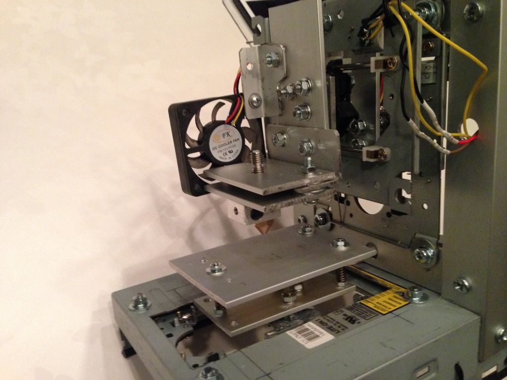 The task is simplified by the fact that the same threaded studs of the DVD drives are used on all axes.
Calibration determines the number of motor steps per 1 mm movement. The parameter depends on engine speed and pulley radius. The adjustment is repeated 3-4 times to ensure increased accuracy.
Mounting the extruder
The extruder module is mounted on a movable frame element that can be moved along the skids in the vertical direction from the Z-axis DVD drive. /MK8. To control the motor, the appropriate drivers are installed: idle extruder, body extruder and laser. The supply of plastic to the heating chamber of the module is carried out through a Teflon tube. The main engine is securely attached to the frame. It needs to be calibrated. To do this, a controlled piece of thread is fed in, which must correspond to a certain travel distance (for example, 10 cm).
Test print
After assembly is completed, a test print of the part is made.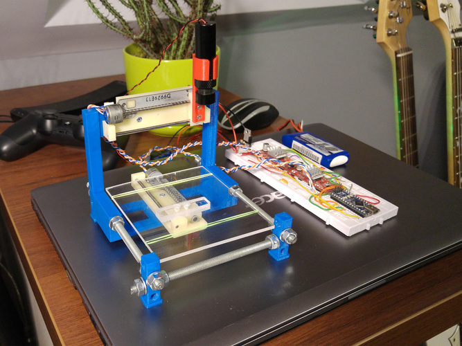 Typically, a PLA filament with a diameter of 1.75 mm is used. The test program in Repetier is activated. It is recommended to start by printing a standard 10 mm cube. Such a part will be produced quickly and without unnecessary material costs, allowing you to evaluate the accuracy of the dimensions in all three axes. For printing, the temperature in the extruder is set within 190–210 °C.
The start point is set before printing starts, i.e. X, Y, Z = 0. The gap between the nozzle and the work surface is set using a sheet of paper. Adjustment along the Z axis provides a gap equal to the thickness of the sheet (Z=0).
What attention is paid to avoiding errors?
When making a 3D printer with your own hands, you should consider the following nuances:
- The main savings are achieved by using DVD drives to provide movement along the axes and designing a homemade frame.
- Do not save on the extruder, the main stepper motor and the gearbox for it.
 You should purchase standard, new products designed for 3D printers, since the performance of the entire device largely depends on them.
 - The power (current) is adjusted with special care to avoid overheating of the motors.
- The print quality depends largely on the correct calibration in all axes. It must be carried out before each start-up of the printer.
- It is important that the platform is perfectly level.
- The guides must have a sufficient degree of machining accuracy for free movement of the head in all axes.
- Standard plastic (usually PLA) should be used for printing. The temperature in the extruder must match the brand of plastic.
With careful assembly and the use of quality parts, you can make a functional 3D printer. Its accuracy is inferior to factory models, but it will be quite sufficient for printing products with practical applications. Home craftsmen have proven that a homemade printer is quite capable of replacing expensive equipment at home.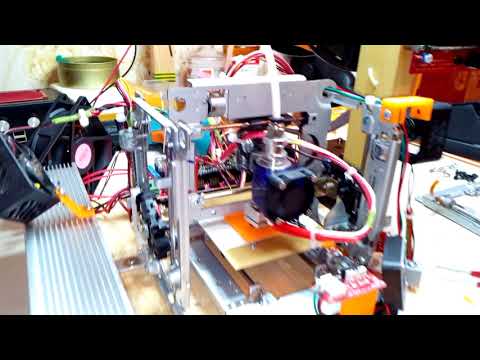
- March 21, 2021
- 1810
Get expert advice
Homemade 3D printer from CD/DVD drives
RepRap
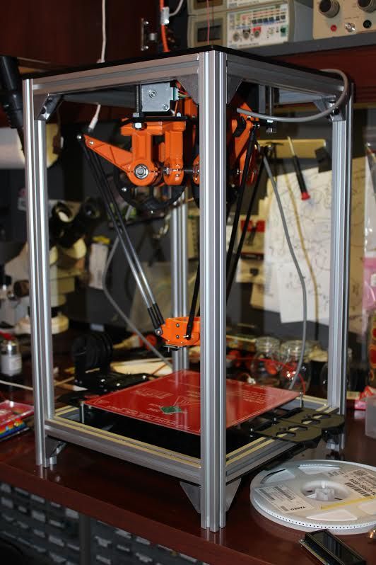
Once there was a desire to assemble your own printer, but there weren’t many funds, and I wanted something compact. And I began to rustle on the World Wide Web, in search of finding someone who did something similar, and of course I found a couple of suitable options.
As a result, after numerous calculations, I came up with what I will do my miracle from - from DISK DRIVES!
Fortunately, among the junk of old computers, I found 4 drives, and put them into action.
I did everything in a hurry, and as a result, there were bumps and jambs in some places, because everything was done on the knee.
That's what happened in the end, it makes no sense to talk about the assembly of this design, everything is simple and clear. What was inside the drives moved outside.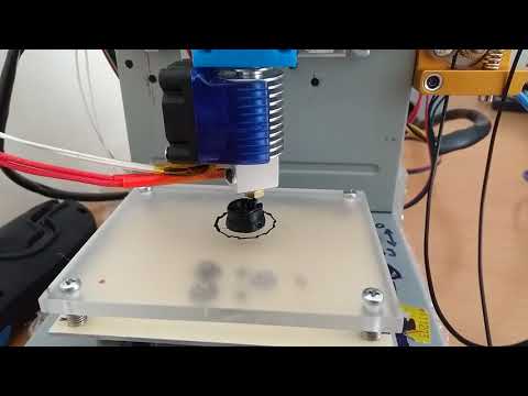
I fixed the Z axis from below with screws for the motherboard, it turned out securely, nothing dangles.
I set the Y-axis sideways to move left and right, and of course, I already attached the X-axis to it, on which the extruder will be attached in the future and not the felt-tip pen.
As a result, I glued the entire BRAIN of this design (Arduino Uno, CNC Shield, firewood A49988, and all the wires connected to this) to the back wall with hot glue.
From above, you can see how ridiculously the Nema 17 stepper is located, the feeding plastic, I have not yet found a better place for it. And on the other hand, a relay for controlling the heating element of the extruder.
Of course, it may not smell like beauty here, but nevertheless it works.
The table is fixed to the drive carriage, and I used rubber bands from it instead of springs as clamping elements and adjusting the table at four points. And on a double-sided tape I glued a work surface - a piece of glass.
Then the question arose of how to feed all this? The answer was not long in coming. As it turned out, I had an old 20pin PC power supply lying around and I converted it.
I took out the block board, removed the long heatsinks, sawed off their tops to fit the drive, and stuffed it inside.
I added some beauty, drilled holes in the lid, and even stuffed a small cooler inside, which is enough for cooling during long-term operation.
The biggest problem in the end was the firmware. I used the TEACUP firmware, which I initially could not understand as needed, then the version is not the same, then in the end the width of the stepper screw is not the same, and so on. But after some time, and having studied the documentation, I found out that yes, like cheers, it prints.
And here are the actual results of the first print:
In principle, so far I've been satisfied with this, and that's enough for now.