Diy lidar 3d scanner
6 DIY 3D Scanners You Can Build at Home
Creating a 3D model of a real object can be done extremely fast if you have a 3D scanner at home. The problem is: 3D scanners are expensive to buy new.
If you're looking for a solution, why not try building your own affordable 3D scanner at home? It might not create perfect 3D models, but it's a cost-effective alternative to buying a 3D scanner.
Is It Cheaper to Build a DIY 3D Scanner?
The cost of buying a decent 3D scanner ranges from $700 to $10,000 at the highest end. On the other hand, building a DIY 3D scanner can cost less than $200—some even as little as $35.
Depending on the resolution of your homemade 3D scanner, you will still have to work to tidy up the 3D model so that it can be used for things like 3D printing, game development, or perhaps design prototyping. But overall, it will still speed up the design process when compared to building a model from scratch.
1. Cheap 3D Printed 3D Scanner
This 3D scanner is built using 3D printed parts, featuring both open source software and open source hardware files. If you choose to install the maximum of four lasers, then the cost of the project comes in at $35 to $50. Once it's built, handling the digital scan will require some legwork to smooth out. But considering its price tag, it's well worth giving it a go.
You can find the STL files and a full build guide on Instructables. Besides the 3D printed components, you will need one to four lasers, a stepper motor, a turntable, and an Arduino Nano to bring it all together. One benefit of this project is that it's been built many times by community makers, resulting in plenty of images and feedback surrounding the project to help fill in any gaps.
2. DIY 3D Scanner Using a DSLR Camera
Another option for building a 3D scanner is to use a DSLR camera and a method called photogrammetry. At its most basic, it involves taking a lot of images of an object from different angles and stitching those photos together in a software program to create a 3D model.
Alongside a DSLR camera, you will need an Arduino, a stepper motor and driver, an LCD screen, and an IR LED. The goal of the hardware is to build a rotating platform that moves by set amounts so that your camera can photograph the object in a very detailed and controlled way. You can find a great explanation of the project on Instructables.
The real difficulty of this project comes in processing the photos. A good photogrammetry program is essential, and that can cost over $150 to license. There is some free software available, but it may come with limitations.
If you're wondering if there is an alternative solution, you can read our guide to how to turn everyday objects into 3D models without a 3D scanner.
3. Optical CT/3D Scanner With Arduino
For something a little different, in this project you will build a 3D scanner that also doubles as an optical CT scanner. This type of scanner will do the trick if you have objects that are semi-transparent, like a gummy bear or a segment of orange. Otherwise, you can use this setup with the photogrammetry method for regular 3D scans.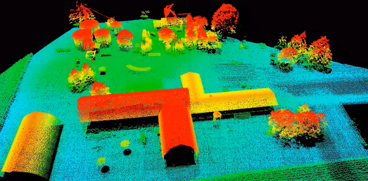
Everything in this build is enclosed inside a box. This allows greater control over lighting the object to produce sharper images. While it involves some woodworking and construction, the hardware is still powered by a humble Arduino Nano, plus additional parts that you can find at any hardware store.
A great guide is available on Instructables for building the box, alongside details for creating a sleek control panel for changing photo parameters on the go.
4. FabScan: Raspberry Pi + Arduino 3D Scanner
This 3D scanner uses both a Raspberry Pi and an Arduino to build a 3D laser scanner. What sets this build apart is that it can be operated remotely via a web browser on a phone.
Much like other DIY 3D scanners, a stepper motor and driver are used to rotate a turntable holding the object you want to scan. Additionally, you will need a line laser and a Raspberry Pi camera. You can find the guide and a full components list on Instructables.
While the creators have gone with a laser-cut MDF box, you can just as easily use spare parts lying around the home to create the enclosure. Alternatively, cardboard can work too, and painting it black will aid in diffusing the laser light so that it doesn't interfere with the scan.
Once you have a good scan of your object, you might be interested in 3D printing it. Haven't got a 3D printer? Here is our pick of the best 3D printers.
5. The Ultimate Human Sized 3D Scanner With Raspberry Pi
While most homemade 3D scanners are built to capture a small object, it's also possible to build a human-sized 3D scanner. The way to do this is with a lot of Raspberry Pis, as you can see over on Instructables.
The maker behind this project scaled up his 3D scanner using a whopping 47 Raspberry Pis plus a Raspberry Pi camera for each module. The goal was to use the photogrammetry method to take a photo of his subject from every possible angle. Because he wanted to capture a 3D model of his two-year-old son, this all had to happen instantly.
Incredibly, it works, and it works very well too. If you have the time and investment to buy a box full of Raspberry Pis, you won't be disappointed because the results are impressive. The maker says you can use fewer Pis and cameras and still get good results, especially if you only need to capture the front of a person’s face.
6. Standalone 3D Scanner
Maybe you're just after a simple and small 3D scanner that you can make over the weekend. If so, then this project will suit you. This 3D scanner on Instructables is designed to be all-in-one, meaning that the photos are compiled onboard and an STL file is saved directly to a memory card. Instead of compiling the photos in a separate photogrammetry program, this 3D scanner handles them for you.
While it doesn't produce incredibly detailed scans, it does make for a rapid way to take a 3D model straight to 3D printing. One thing to bear in mind, however, is that the dimensions of the 3D scanner structure need to be kept exactly as written in order to match the code.
Building a Homemade 3D Scanner
Putting together a 3D scanner at home isn't extremely difficult to achieve. When compared to the expensive price of commercial 3D scanners, it's well worth building a DIY 3D scanner yourself.
With a Raspberry Pi or Arduino and a few extra affordable parts, you'll be well on your way to creating a cheap and awesome 3D scanner.
9 Accurate DIY 3D Scanners You Can 3D Print At Home (2022)
3D scanners can get really expensive. We’d know – we’ve tested and researched them in creating our ranking of the best 3D scanners . However, if you’re willing to be a little more thrifty you can save a lot of money building your own DIY 3D scanner — and have a cheap 3D scanner you can feel proud of building yourself!
DIY projects, especially in an area where precision is key, have an unfairly slap-dash reputation. In fact, there are some very accurate DIY 3D scanners on our list, you just need to assemble them yourself.
The best part: they’re almost free if you 3D print the parts — your only costs are the camera/parts.
However, don’t be fooled – you won’t get $20,000-quality scans from these kits.
And, it takes focus and skill to build such a technical piece of kit – hence we’ve included a couple of easy-assemble kits which cost more, but let you get right down to scanning.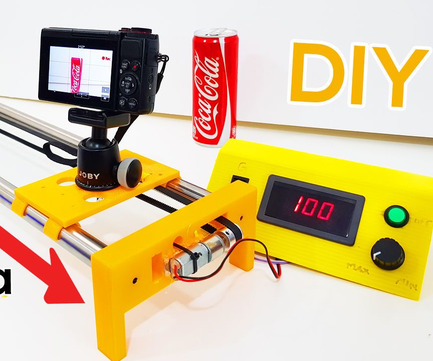
Best DIY 3D Scanner Kit Under $200
HE3D Open Source Ciclop DIY 3D Systems Scanner Kit for 3D Printer
$159.00
Amazon here
Best 3D Scanner Under $1000
$719.00
Amazon here
12/17/2022 05:51 am GMT
Top Picks
Best DIY Scanners – Full Round-Up
- BQ Ciclop: Best 3D scanner kit overall
- Murobo Atlas: Good Ciclop DIY scanner alternative
- Cowtech Ciclop: Upgraded premium Ciclop scanner
- Openscan: Great open source 3D scanner
- AAScan: Great option for Android
- Revopoint POP 2: Best semi-assembled 3D scanner to save you time
For the DIY kits, we’ve included download links and links to documentation to get you started.
But first, let’s cover what to look for in a good homemade 3D scanner:
What Makes a Good DIY 3D Scanner?
- Price-performance ratio: for the price, how good are scans?
- Resolution: how crisp is scan quality
- Accessibility: you may be able to print most of the 3D scanner, but are the rest of the parts easy to buy?
- Ease of assembly and use: quick and easy builds are always better.
 The best 3D scanner projects can be built by anyone, newbie or expert.
The Best 3D Printable 3D Scanner Kits
Ciclop DIY 3D scanners
Many of the best DIY scanner kits are based on the original Ciclop open-source files. Massive companies like BQ have created their version, as well as tweaked versions such as CowTech Engineering’s take.
We’ve included them all here, as each option are some of the most DIY accurate 3D scanner options for this price range. For a pre-assembled scanner with the same quality, you’d likely need to spend double this.
3DSourced is reader-supported. When you buy through links on our site, we may earn an affiliate commission. Learn more
BQ Ciclop
- Resolution: 0.3-0.5mm
- DIY 3D scanner technology: laser triangulation
- Price: around $150 — Available on Amazon worldwide here
BQ are a Spanish technology giant who are well-known across Europe for their smartphones, tablets, and 3D printers. They’ve also developed their Ciclop DIY 3D scanner, which scans a volume up to 250 x 205 mm, based on laser triangulation technology.
An important feature of the BQ Ciclop is that it’s a completely open source 3D scanner. You’re free to modify it as you wish, following the RepRap philosophy. It’s easily accessible via USB or Bluetooth, and can 3D scan with a resolution of between 0.3-0.5mm.
- We also have a ranking of the best open source 3D printers.
Another great addition to this DIY 3D scanner is that it works with Horus open source 3D scanning suite which BQ also developed. This makes scanning much easier with the compatible program. You can buy just the electronics (includes an Arduino, webcam etc) and print the parts yourself for $115, or buy the whole kit for $240. Not bad.
However, it is worthy of note that the BQ Ciclop is difficult to assemble. Other DIY 3D scanners are quicker and simpler to build, though the Ciclop is still a fantastic DIY 3D digitizer.
Best DIY 3D Scanner Kit Under $200
HE3D Open Source Ciclop DIY 3D Systems Scanner Kit for 3D Printer
$159.00
Yes, you'll get better quality if you spend more on a scanner like the Revopoint POP range, but with this you get to build your own 3D scanner from the parts for several hundred dollars less.
Amazon here
We earn a commission if you make a purchase, at no additional cost to you.
12/17/2022 05:51 am GMT
Murobo Atlas — Great Raspberry Pi 3D Scanner
- Resolution: 0.25mm
- DIY 3D scanner technology: laser triangulation technology
- Price: $200-250 — Available on Amazon worldwide here
Another homemade 3D scanner, the Atlas has the highest quality specs of any DIY 3D scanner we researched. It includes a 3D printed body made from PLA and ABS filaments, which can be purchased online. If you’re a serious DIY fanatic, you can print the parts yourself via the download link here.
Depending on if you already own a Raspberry Pi or not, you can save money on the build. This is because the Atlas DIY 3D scanner uses a Raspberry Pi camera to take detailed 3D scans with an accuracy of 0.25mm. Depending on your choice, the Atlas is likely to cost between $200 and $250, which is far less than most professional 3D scanners.
Moreover, Murobo has made considerable efforts to make sure that the Atlas DIY 3D scanner is convenient and simple to use. To achieve this, the Atlas comes with FreeLSS free 3D software which enables you to easily take 3D scans. In addition, you can access your Atlas via your computer’s browser through WiFi, as well as via SD card.
Overall, this DIY 3D scanner Raspberry Pi collaboration is a really interesting and creative way of combining several different innovative technologies to create a scanning device. If you’re an Arduino fan instead, you may be able to make it work for you too.
CowTech Ciclop
- Price: $119 – $159 (depending on whether you’re 3D printing the parts or not) — Available on Amazon here
- Resolution: 0.5 mm
- Maximum scan volume: 200 x 200 x 205 mm
BQ formed the foundations of the DIY 3D scanner kit, and remains one of the best DIY 3D scanner on tight budget options. Then back in 2015, CowTech Engineering used the foundations led by BQ, putting their unique spin on an updated model.
True to the open source movement, Cowtech started a Kickstarter campaign to raise money to put their version of the original, the CowTech Ciclop, into production. The team set the lofty goal to raise $10,000, and were met with surprise when the community rallies to raise $183,000. The CowTech Ciclop DIY 3D scanner kit was born.
So what are the differences between CowTech’s version and BQ’s DIY 3D scanner?
The CowTech Ciclop still uses the Horus 3D software program as it does a fantastic shop for 3D scanning objects. Differences however include a slightly different design, which the team spent days designing so that the parts could be 3D printed on any FDM 3D printer. Some desktop 3D printers only have a small build volume, so CowTech designed parts that can be printed on any printer with a build volume of 115 x 110 x 65 mm, which almost all 3D printers have.
Additionally, CowTech’s Ciclop has adjustable laser holders, and whereas the BQ Ciclop uses threaded rods, CowTech’s DIY 3D scanner uses laser-cut acrylic. This isn’t anything drastic and the scanners still look fairly similar, but CowTech only intended to improve the existing design, not reform it. CowTech sell the Ciclop, ready-to-scan, for $159 on their website. Overall, this is a great cheap DIY 3D scanner, and very effective for laser triangulation 3D scanning.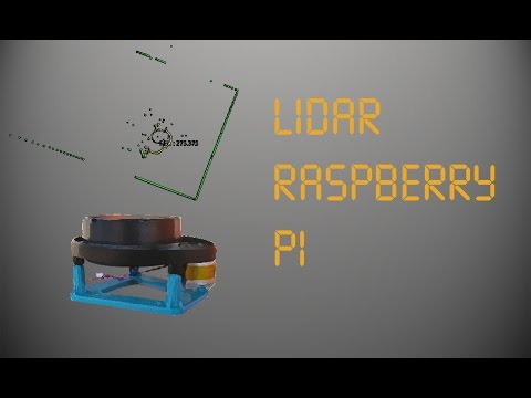
OpenScan Classic and OpenScan Mini
- Max Scan Volume: 180 x 180 x 180 mm / 80 x 80 x 80 mm
- Accuracy: Up to 50 microns
- DIY 3D scanner technology: Photogrammetry
- Price: Starting at $100.00 up to $200.00 for a complete kit with 3D printed parts and electronic
The Mini and Classic are two low-cost but high-quality 3D printed DIY scanner projects designed by German company OpenScan. In action, the OpenScan uses a stepper motor mounted to a 3D printed frame to rotate an object to capture images from various angles. These are then compiled into a high-quality 3D model using open-source software or OpenScanCloud, ready for 3D printing.
Where the OpenScan Classic and Mini differ from one another is max scan volume and camera/SBC options. The Mini features an 80 x 80 x 80 mm scan volume, while the Classic more than doubles the scan volume to a roomy 180 x 180 x 180 mm, perfect for scanning larger objects. The Openscan Mini – the cheaper and smaller 3D printable 3D scanner.
The OpenScan Mini is tied to a Raspberry Pi and only works with either a Pi Camera or Arducam IMX 519 and includes one-click easy scanning. This allows the completed scanner to rotate not just the object but also the camera for a more detailed point cloud.
On the other hand, the OpenScan Classic is also compatible with Smartphones and DSLR cameras, which generally means better quality photos and, as a result, higher-quality models. It’s the tinkerer’s option and better suited for those that want to customize the scanner to their needs.
OpenScan offers a solution for all DIY skill levels and budgets, whichever model you decide on. You can customize kits based on your needs or order a complete kit that includes all the electronics and 3D printed parts.
The full assembly guide is here.
AAScan Open Source 3D Scanner Based on Arduino and Android
AAScan is a very recent (February 2020) DIY open source 3D scanner that’s fully automated in taking photos and moving the object around on the scan plate.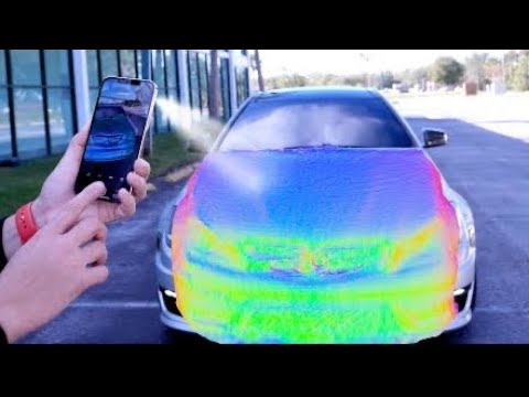 All the files are on Thingiverse, which we’ve linked below. Interestingly, the creator stresses that the AAScan is intended to be a purposefully minimalist machine, able to scan but not filled with extra features beyond this primary capacity.
All the instructions for how to build, print and assemble the AAScan are on the Thingiverse page, requiring an Arduino, some electronics, and either a 3D printer to print the plastic parts or someone else to print them for you — such as from a 3D printing service.
You can view the DIY scanner on Thingiverse here.
FabScan Pi
- DIY 3D scanner technology: laser triangulation
- Price: $100-200 depending on which version
The original FabScan was a DIY 3D scanner built by Francis Engelmann as part of his Bachelor’s thesis back in 2010. Since then, there have been numerous improvements made in new iterations up to the newest model, the FabScan Pi. This new model uses a Raspberry Pi camera along with the new design to offer higher quality 3D scans.
Based on laser triangulation technology, the FabScan Pi is one of the best DIY 3D scanner options for those who are into doing it themselves. Depending on if you go for one of the older models or the latest, the price can vary between $100 and around $200 to completely create the 3D scanner. Overall, it’s a really cool kit and thesis which you can make at home.
If you want to create your own FabScan, you can follow the assembly guide here.
DIY Standalone 3D Scanner by Jun Takeda
- DIY 3D scanner technology: Photogrammetry
- Price: $200.00
The DIY Standalone 3D Scanner is an excellent option for those that want a hands-on project that results in a reasonably accurate and easy-to-use stationary 3D scanner.
By combining a Mbed board with a camera and OpenCV libraries, the scanning process is largely automated with just a single button push. The scanner captures multiple images of an object to create a 3D model that’s then output as an STL file written to an SD Card.
To complete the project, you’ll need a GR-LYCHEE as a centerpiece sided by smaller electronic parts, plastic sheets to create the housing, and various nuts and wiring to piece it all together.
As the name implies, it’s very much a DIY project and, as such, would best suit those happy to troubleshoot any potential hurdles with little hand-holding. Though there are instructions, you’re responsible for designing the housing, wiring the board, and calibrating the camera.
Arduino-Controlled Photogrammetry 3D Scanner by Brian Brocken
- DIY 3D scanner technology: Photogrammetry
- Price: ~$100
The Arduino-Controlled Photogrammetry 3D Scanner is a 3D printable 3D scanner DIY project that leverages the camera on any run-of-the-mill Smartphone and a cheap Arduino UNO SBC to keep costs low.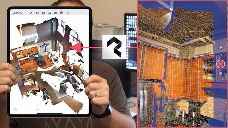
The core idea is to assemble a turntable consisting of 3D printed mechanical parts, including a print-in-place bearing. A Bluetooth-connected Smartphone does the actual scanning via the normal photogrammetry process. As for electronic components, you’ll need a servo motor, LCD screen, Arduino Uno, PCB, stepper motor, Bluetooth remote, regulator, and a small joystick module.
Once assembled, the Arduino-Controlled Photogrammetry 3D Scanner can capture anywhere from 2 to 200 photos in a single 360° rotation for reasonably detailed scans. The images are then sent to photogrammetry software such as AutoDesk Recap Photo to assemble a 3D model.
Aside from the cost of filament, expect to pay no more than $100 for all the parts and the STL files to 3D print the turntable.
Semi-assembled DIY scanners
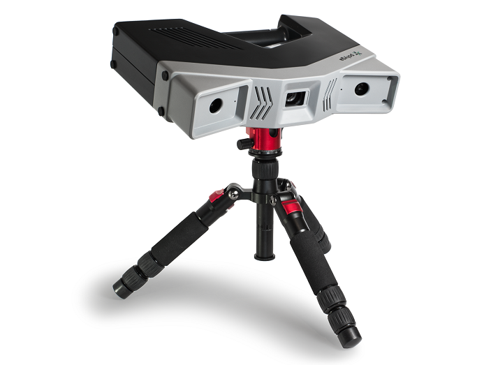
Revopoint POP / POP 2
- Price: $500-700 — Available at Revopoint store here
- Accuracy: 0.3 mm
- Max Scan Volume: 200 x 300 x 300 mm
- Scan Speed: Up to 8 FPS
- DIY 3D scanner technology: Structured light
Though not technically a DIY scanner, we thought we’d slide in the Revopoint POP as a cheat option for those that want to save time and want largely better quality scans than you’d get with a homemade alternative.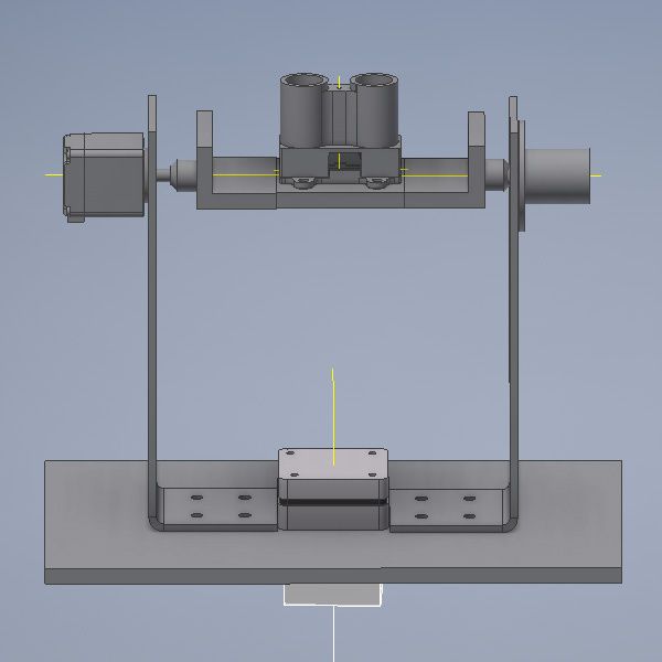
It comes semi-assembled – you just need to attach the tripod, connect the USB and the turntable, add the sticker markers for better scan tracking, and optionally build and attach the larger turntable – so you can get started in just 5 minutes!
A basic mug scan we did on our Revopoint POP 2.The catch? At around $500, the Revopoint POP is considerably pricier than a DIY scanner. Still, it may be worth paying the premium for the convenience and reliability.
The Revopoint POP offers 0.3 mm accuracy (the POP 2 offers within 0.1 mm!) and automatic alignment technology, making for more detailed and smooth full-color 3D models than DIY scanners. It can capture 360° scans of objects up to 200 x 300 x 300 mm, besting most DIY options.
The main benefit of all this is high accuracy scans that are just about ready for 3D printing with very little post-processing needed to iron out imperfections and poor surface details.
A statue scan we did with our Revopoint POP 2.Ease of use also extends to the intuitive software, which works with Smartphones for on-the-go scanning and features exports to STL and OBJ formats. Alongside, it bundles in best-of both-worlds handheld and stationary modes. Five different scanning profiles allow you to tune the POP to each scan with face, body, feature, mark, and dark mode.
Read more: we tested and reviewed the Revopoint POP 2
Best 3D Scanner Under $1000
Revopoint POP 2 3D High-Precision Scanner with 0.05mm Accuracy
$719.00
You'll see just how accurate this scanner is when you try it (I've tested it to confirm a 0.07mm accuracy in my hands-on review) - there's nothing better for under $1000.
Revopoint hereAmazon here
We earn a commission if you make a purchase, at no additional cost to you.
Can You Make a 3D Scanner?
- Choose a DIY 3D scanner design.
- Source the non-3D printable parts such as the camera, stepper motor, single board computer (such as an Arduino), wiring, and other electronic parts.
- 3D print the housing, brackets, turntable, mounts, and other parts required for the 3D scanner project.
- Wire and assemble all the parts.
- Configure and set up the single board computer.
- Test and scan.
FAQs
Which is the Best DIY 3D Scanner?
This depends on how much DIY you want to take on yourself, and how much you are ready to spend.
One of the most cost-effective options is scanners based on the Ciclop open-source 3D scanner design. You can purchase a low-cost Ciclop scanner like the BQ Ciclop or CowTech Ciclop 3D scanner, then 3D print the parts from home and modify and tune the scanner to your liking.
Alternatively, the Revopoint POP is an excellent semi-assembled 3D scanner with great specifications and software at an affordable price for those that want to save time.
What is a DIY 3D Scanner?
A DIY 3D scanner is a cost-effective, home-made device constructed from manufactured or 3D printed parts designed to capture the characteristics of a specific object – such as size, surface details, and shape – by scanning it from multiple angles to create an equivalent point cloud that can be processed into a 3D model via software.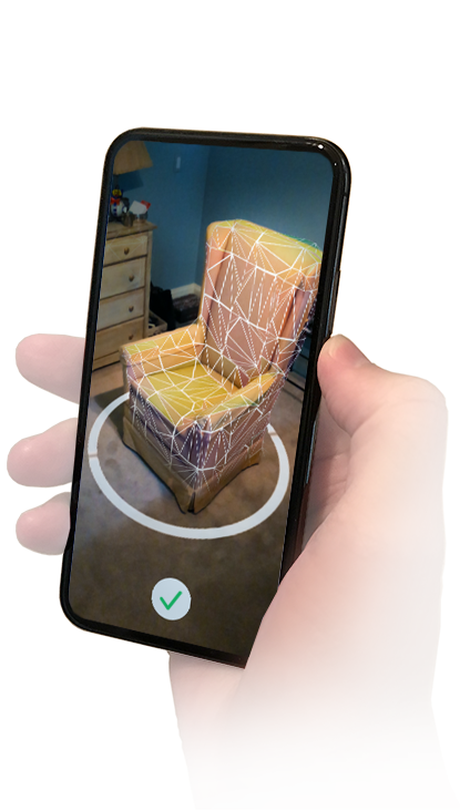
Other articles you may be interested in:
- The best 3D scanners
- The best low-cost 3D scanners
- Top 3D scanner apps for iOS and Android
- The best photogrammetry software
- Structured light 3D scanning vs laser scanning
- 3D body scanners: a guide
- Industrial 3D scanners
how to assemble a 3D scanner from scrap materials and digitize reality — T&P
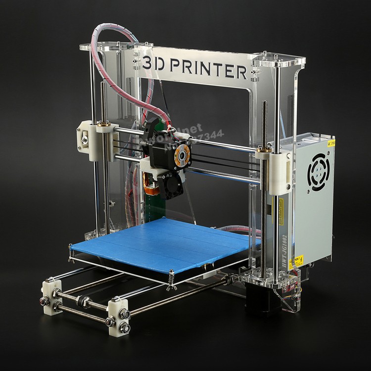
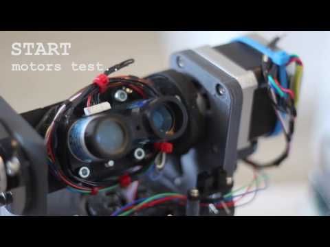
The first 3D printers that cost less than a gaming computer have become a mandatory attribute of almost any hackspace or fablab (laboratory of technical creativity and electronic art). Now 3D scanners have joined them. MIPT student and employee of the Polytechnic Museum Daniil Velovaty himself assembled a three-dimensional scanner from a laser, a webcam, and scrap materials. As part of the special project Phystech. Reader" he told T&P about the future of reality scanning. nine0003
Daniil Velovaty
It was easy to get used to 3D printers: I drew the desired detail or figure on the computer, loaded it into the printer, and a few hours later I took its embodiment in plastic.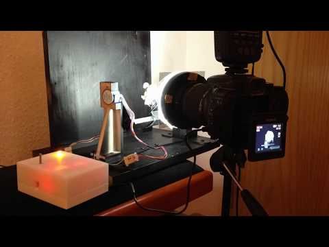 Yes, what about plastic, they are already printing in metal, and even in organic matter: they recently printed a living liver. No wonder you want to go further. The next step is scanning. Oddly enough, but before the advent of 3D printers, there was no great need to transfer a real object to the digital world: the creators of games and films simply hired artists who drew whatever was needed. The need for scanners arose only when it was important to convey the relief and shape of an object with very high accuracy. At the same time, neither the duration of the scan nor the cost were often completely unimportant. This is how the first representatives of 3D scanners appeared: lidars. nine0007
Lidar (from English Light Detection and Ranging) is an expensive but very accurate device. It allows you to build 3D models of objects with an accuracy of millimeters, the size of which can be compared with the size of a building. From the decoding of the abbreviation LIDAR, it follows that it is any rangefinder that measures distance using light.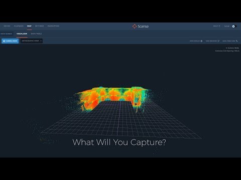 An incredible number of devices fall under this description. But most often, devices like this are called lidars:
A special system of mirrors is placed inside the device. A phase laser rangefinder is installed here, which measures the distance using a laser, and two mirrors serve to deflect the laser beam in two planes. Thus, the ray runs through a certain sector of space and builds its 3D model. As you might guess, the speed of such a scanner depends on the speed of the rangefinder and the speed of rotation of the mirrors. And since all this is quite complex equipment that requires fine tuning, it costs quite a lot of money. It is much more profitable to order a scan than to buy the machine itself. Moreover, you still need to figure out how to use it. nine0007
As industrial devices were, to put it mildly, beyond the reach of the average consumer, and the need to scan reality grew, cheap desktop and handheld 3D scanners appeared. The former, as a rule, have a turntable on which the object under study is placed.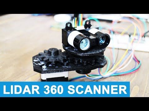 A few minutes after the start of the scan, we will get the finished model. Of course, the scan quality and the size of the scanned area are incomparable with lidars, but they cost several orders of magnitude cheaper. It is to this class of devices that the scanner we developed belongs. The main problem with these scanners is that the object to be scanned must fit on a turntable, which greatly limits the scope. Another significant disadvantage of these scanners is the incompleteness of scanning and blind spots. If, for example, you try to scan a vase, the scanner will only see its outer part, and not the cavity inside. nine0007
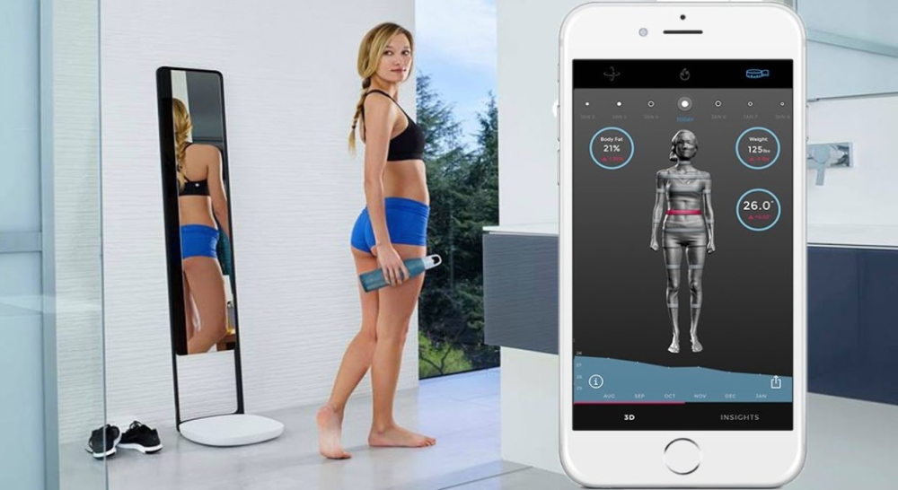
The second type of scanners are handheld 3D scanners. They need to be moved around the object by hand, but they build a model with the help of cameras. The operation algorithm of such scanners is much more complicated, they are more expensive, and the quality of the result is worse, but they allow you to scan large objects and spend less time on it. They look something like this:
One of the main advantages of such a scanner is that it is not limited by the scanning area. We can scan, for example, a person's face without having to place their head on a turntable. With a certain diligence, even an entire room can be scanned, if only the positioning accuracy allows it. To improve accuracy, you can stick special marks that the scanner finds and uses as reference points. Actually, in the photo above, this is what was done. This approach limits the scanning area, but, unfortunately, here either the sheep are safe or the wolves are full. nine0007
In our lab, we decided to create a cheap 3D scanner with an accuracy comparable to that of 3D printing. This was our first serious project, so we made mistakes, misunderstood a lot, and learned even more along the way. We first built a simple laser rangefinder using a laser pointer and a webcam. To understand how a 2D camera can measure distance, you have to use your imagination. Imagine a thread stretched in the air, along which a spider is crawling. If we stand close to the rope, we see how the spider is crawling straight towards us (not a very pleasant sight).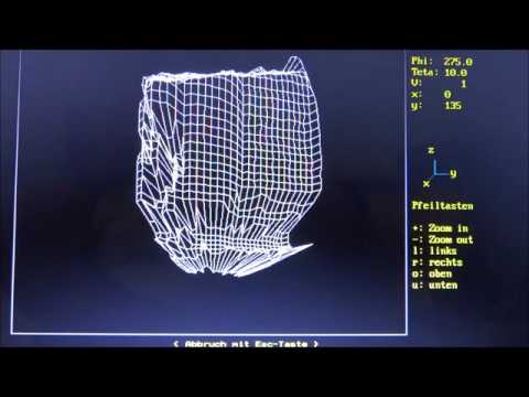 And if now we shine a lamp on this whole structure from the side, we will see a shadow on the floor. Since the light comes from the side, the projection of the spider will move along the projection of the thread. By measuring the distance from the beginning of the thread's shadow to the spider's shadow, we can calculate how far the spider has crawled by multiplying by some factor, because we are creating a contraction mapping. nine0007
Our scanner works in approximately the same way. Only instead of a thread - a laser beam, and instead of a screen with a shadow - a camera. Just as a spider moves along a thread, a spot moves along the laser beam, which occurs when this beam encounters an obstacle. Having found the position of the spot in the photograph, we can determine the distance to the object on which this spot is located. In words, it is difficult. It looks simpler in the picture:
The farther the wall, the closer to the dotted line will be the pfc point on the camera matrix
But such a rangefinder measures the distance to a single point, and this takes a very long time.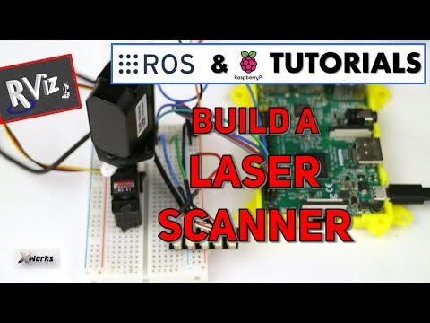 Therefore, we put a lens on the laser, which turns the laser spot into a laser line. Now we measure the distance to hundreds of points at once (after all, a line can be represented as a set of points), it remains to build a system that allows this line to go through the entire object, and for this we need a turntable on which the object is placed.
The scanner itself is assembled from plywood pieces that have been laser cut. To rotate the table, a stepper motor is used, which is controlled by a board developed by us. It also controls the brightness of the laser and backlight. nine0007
The image from the camera is processed on a computer; a Java program was written for this. After scanning is completed, the program generates a so-called point cloud, which, using another program, are combined into a full-fledged model. This model can already be printed on a 3D printer, that is, a copy of a real object can be obtained.
Don't miss the next lecture:
Theory and practice
Tags
#3D printers
#MIPT
#technology
-
9 191
3D laser scanner on Android phone / Habr
I present to your attention a DIY scanner based on an Android smartphone.
When designing and creating a scanner, first of all, we were interested in scanning large objects. At least - a full-length figure of a person with an accuracy of at least 1-2 mm.
These criteria have been successfully met. Objects are successfully scanned in natural light (without direct sunlight). The scanning field is determined by the capture angle of the smartphone camera and the distance at which the laser beam remains bright enough for detection (during the day indoors). This is a full-length human figure (1.8 meters) with a grip width of 1.2 meters. nine0007
The scanner was made for reasons of "whether to do something more or less useful and interesting when there is nothing to do." All illustrations are based on the example of a “test” object (it is not correct to post scans of people).
As experience has shown, for a scanner of this type, software is secondary and the least time was spent on it (on the final version. Not counting experiments and dead ends). Therefore, in the article I will not touch on the features of the software (Link to source codes at the end of the article.)
The purpose of this article is to talk about the dead ends and issues collected along the way to creating the final working version.
For the scanner in the final version is used:
- Samsung S5 phone
- 30mW red and green lasers with line lens (90 degree line) with glass optics (not the cheapest).
- Stepper motors 35BYGHM302-06LA 0.3A, 0.9°
- Stepper motor drivers A4988 nine0051 Bluetooth module HC-05
- STM32F103C8t board
The A4988 drivers are set to half step, which with a 15->120 reducer gives 400*2*8 steps per PI.
Select the scanning technology.
The following different options were considered.
LED Projector.
The option was considered and calculated.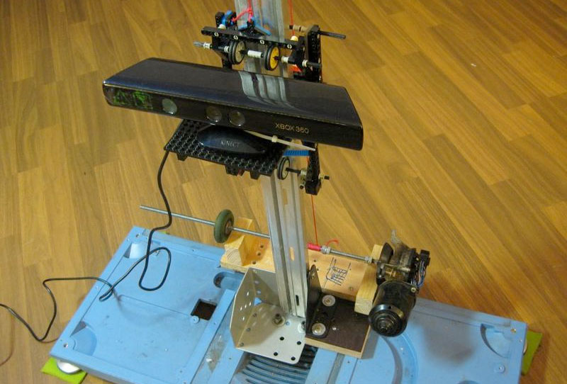 Even expensive projectors do not have the required resolution to achieve the required accuracy. And it makes no sense to even talk about cheap ones. nine0007
Mechanical sweep of the laser beam in combination with a diffraction grating.
The idea was tested and found to be suitable. But not for DIY performance, for reasons:
- A sufficiently powerful laser is needed so that after diffraction the marks are bright enough (the distance to the smartphone lens is 1..2 meters). And the eyes are pitiful. A laser point already with 30mW is not useful.
- 2D mechanical reamer accuracy requirements too high for DIY. nine0054
Standard mechanical scanning of the laser line on a stationary scanned object.
In the end, a variant with two lasers of different colors was chosen.

As it turned out, the last criterion is the most important. The quality of the scan is entirely determined by the accuracy of measuring the geometric dimensions and angles of the scanner. And the presence of two scans from two lasers allows you to immediately evaluate the quality of the scan:
The point clouds converged. Those. the planes captured by the two lasers converged over the entire surface.
Although from the very beginning I assumed that this was a dead end version that did not provide the necessary accuracy, I still tested it with various tricks:0007
- The motor shaft is fixed with a bearing.
- Added a friction element and a stopper for reducing gear backlash.
- An attempt to determine the "exact position" by a phototransistor, by laser illumination
The repeatability of returning to the same place of the laser line was low - 2-3 mm at a distance of 1. 5 meters. During the operation of the gearbox, despite the apparent smoothness, jerks of 1-3 mm are noticeable at a distance of 1.5 meters.
i.e. 28BYJ-48 is completely unsuitable for a more or less accurate large object scanner. nine0007
Reamer requirements based on my experience
Reamer must be a mandatory element.
Make no mistake about the 1/x step mode. Experiments have shown that in 1/16 mode on the A4988 the micro steps are not uniform. And at 1/8 this unevenness is noticeable to the eye.
The best solution for the gearbox was the use of a belt gear. Although it turned out to be quite cumbersome, it is easy to create and accurate.
The positioning accuracy (more precisely, the repeatability of the positioning of the initial position of the lasers for scanning) of the lasers turned out to be about 0.5 mm for a 5 mm laser line width at a distance of 4 meters. Those. at a scanning distance (1.2-1.8 meters) it is generally difficult to measure. nine0007
Positioning - optocouplers (Chinese noname) on a slot in the disk under the lasers.
Problems with the transmission of control signals from the phone to the laser and stepper motor control module
The bottleneck in terms of scanning speed was the control channel. Since this was a DIY leisurely development for my own pleasure, we tried all the ways to communicate with a smartphone.
Transmission of control signals via Audio jack (phone Audio jack=> oscilloscope)
The slowest way to transfer data in real time. Yes, even with floating time. Up to 500 ms (!) from software activation of audio data transfer to the actual appearance of a signal in the Audio jack.
This exotic was tested because, at work, I had to deal with mobile chip card readers.
Photodiodes on the smartphone screen (a piece of the phone screen => phototransistors + STM32F103)
For the sake of interest, even such an exotic method was tested as phototransistors with a 2x2 matrix in the form of a clothespin on the screen. nine0007
Although this method of issuing information from the phone turned out to be the fastest, it is not so fundamentally faster (10 ms vs 50ms) than Bluetooth to put up with its shortcomings (a clothespin on the screen).
IR channel (phone=>TSOP1736->STM32F103)
The method of transmission through the IR channel has also been practically tested. Even some implementation of the data transfer protocol had to be done.
But IR also turned out to be not very convenient (it is inconvenient to mount a photo sensor on a phone), and not too faster than Bluetooth. nine0007
WiFi module (phone=>ESP8266-RS232->STM32F103)
The results of testing this module were completely discouraging. The request-response execution time (echo) turned out to be unpredictably floating in the range of 20-300 ms (average 150 ms). Why and what - did not understand. I just came across an article that talked about an unsuccessful attempt to use the ESP8266 for real-time data exchange with strict request / response time requirements.
i.e. ESP8266 with "standard" firmware TCP -> RS232 is not suitable for such purposes. nine0007
Selected control unit and signal transmission
Ultimately, after all the experiments, the Bluetooth (HC-05 module) channel was chosen. Gives a stable (and this is the most important) data transfer request-response time of 40ms.
The time is quite long and greatly affects the scan time (half of the total time).
But the best option was not achieved.
Widespread board with SM32F103C8T as control module. nine0007
Line detection methods on the frame.
The easiest way to highlight the laser lines on the frame is to use the subtraction of the frame with the laser off and the frame with the laser.
In principle, search by frame without subtraction also works. But it works much worse in daylight. Although this mode was left in the software for the sake of comparative tests (the photo of the mode is below.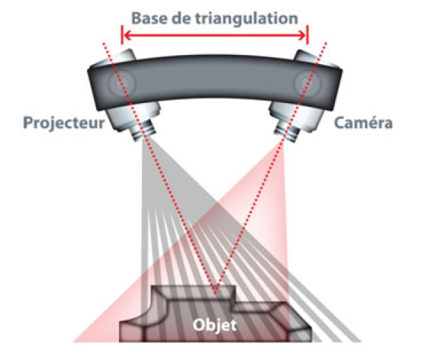 All other photos with the frame subtraction mode).
The practical value of the variant without frame subtraction turned out to be low. nine0007
It is possible and possible to extract the laser signal from this noisy information. However, he did not bother.
Frame subtraction works well.
All sorts of experiments with attempts to approximate the line and processing the entire frame have shown that the more complex the algorithm, the more often it "mistakes" and even slows down the processing "on the fly". The fastest (and simplest) algorithm was found to search for a laser (laser point) on a horizontal line:
- For each line point, the sum of the squares of the laser color level (RGB) in the window specified in the configuration (13 px is the experimentally optimal value for the window) is calculated nine0054
- Laser point - the middle of the window with the maximum value of sums of "color" levels.
The time for processing one frame by searching for the "green" and "red lines" is 3ms.
Point clouds for red and green laser are counted separately. With correct mechanical alignment, they converge with an accuracy of < 1 mm.
Accuracy and adjustment
The accuracy was within 1 mm at a distance of 1.2 meters. Mostly due to the resolution of the phone's camera (1920x1080) and laser beam width.
It is very important to make static and dynamic adjustments to get correct scans. The accuracy / inaccuracy of the settings is clearly visible when both point clouds are loaded into MeshLab. Ideally, the point clouds should converge, complementing each other.
Static parameters, set as accurately as possible once:
- Tangent of the camera's field of view.
- The length of the "shoulders" of the lasers (from the center of the lens to the axis of rotation). nine0085
And of course, the maximum focusing of the laser lenses at a given scanning distance and the “verticality” of the laser lines.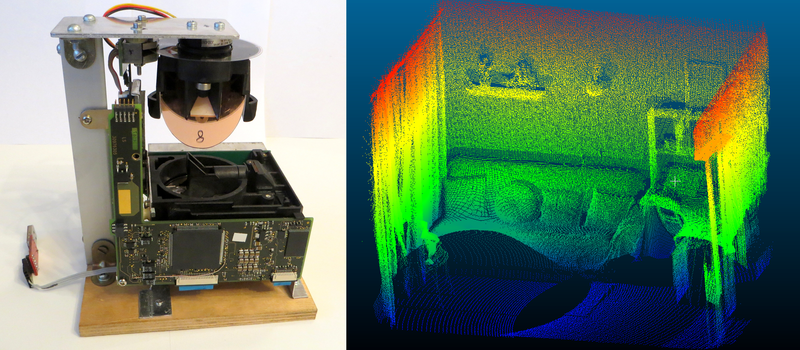
The dynamic parameter of the actual position angle of the lasers relative to the virtual plane of the frame has to be re-adjusted every time the phone is mixed in the mount. To do this, the setup mode in the software is made. By bringing the lasers to the center of the screen and adjusting the angle, it is necessary to set the calculated distance as close as possible to the true (measured) distance for both lasers. nine0007
Before adjustment:
After adjustment:
Pins
Such a design, perhaps, can be repeated by anyone. I cut out all the details from fiberglass on the CNC.
Of course, without a CNC router, it is difficult to make a pulley for a laser. But taking into account the fact that you need a maximum angle of rotation of 90 degrees, then with due patience, the pulley can also be cut with a needle file.
But it is still better to do it on the CNC. The requirements for axial clearance of the swivel assembly are high.