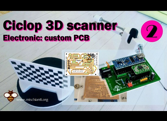
Ciclop 3d scanner assembly
component printing and assembly – 1 – Renzo Mischianti
Spread the love
Support forum
I built the Ciclop 3D scanner, and I encountered some problems, such as the disappearance of the documentation from the web, now it is more difficult to find materials and components and more, I hope to allow others to overcome the problems I have had in this series of articles.
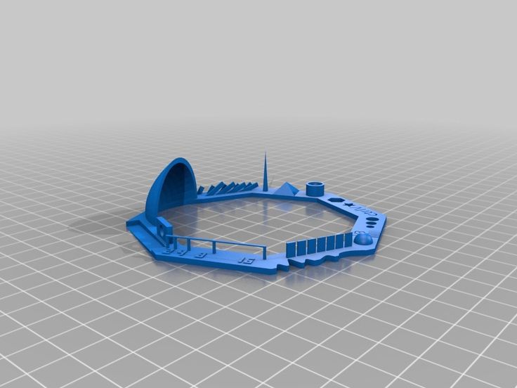
Ciclop 3D scanner 3D printed structure assemblyIn this article I enter all the steps for 3D printing and assembling the structure, I have made some corrections to simplify the process.
Printing and Assembly Parts
The original documentation has disappeared from the internet, so I retrieve some documents in exotic languages and take the photos to write this assembly tutorial.
- 1 x Ball bearing 16014
- 1 x Black methacrylate disc Ø200 x 8 mm
- 3 x Bearing anchor printed part
- 1 x Non-slip surface Ø200 mm
- 2 x Black threaded rod M8 x 400 mm
- 1 x M8 x 292mm Black Threaded Rod
- 4 x Black threaded rod M8 x 170 mm
- 1 x Printed part of motor bracket
- 1 x Camera Bracket Printed Part
- 2 x Printed laser holder part
- 1 x Printed part of motor-disc socket
- 1 x Nema bipolar stepper motor (1.
7A 1.8 deg / step) with connector *
- 7 x Screw M3 x 10 mm – DIN-912 class 8.8 black
- 3 x Screw M8 x 30 mm – DIN 931 class 8 black
- 3 x M3 nut – DIN 934 class 8 black
- 28 x M8 nut – DIN 934 class 8 black
- 18 x Washer M8 – DIN-125 class 6 black
- 6 x Non-slip silicone drops
- 1 x Allen key
Disk mounting
I created a simple STL to allow you to print the disc with the 3D printer to replace the methacrylate one, refer to “3D Printed base for Ciclop 3D Scanner“.
Ciclop 3D Scanner round base semi assembledDisk holder
Bearing clip
Here the list of material.
You can find here Aliexpress Ball Bearing 16014
Ciclop 3D scanner disk mount parts- Disc holder printed part
- Bearing anchor clip
- M8 x 30 mm screw
- Ball bearing 16014
- Methacrylate disc Ø200 mm
- Non-slip surface Ø200 mm
Hold the disc (5), on its bracket (1) and bearing anchor clips (2) together when tightening each screw.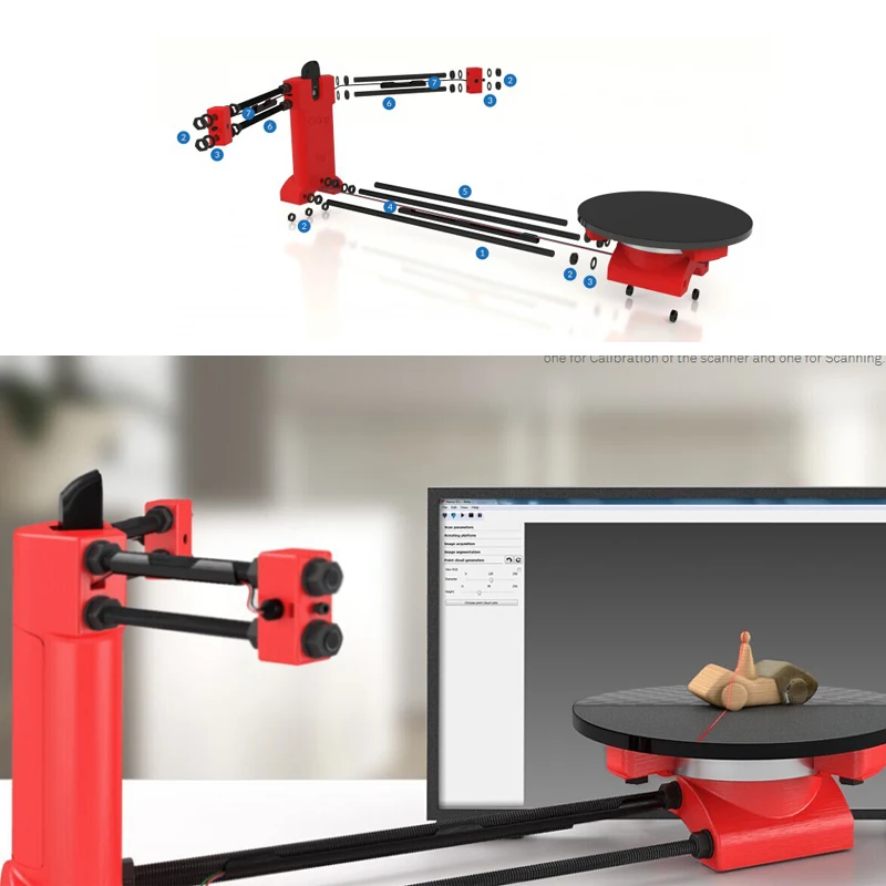
To tighten the screws use a 13 mm spanner.
Assembly of the structure: preparation of the rods
Ciclop 3D scanner rod mount parts- Newly assembled elements
- Nut M8
- Camera support printed part
- Printed motor support part
Insert the screw and nut like the image.
Ciclop 3D scanner rod mount assemblyAssembly of the structure: thread central rods
Camera holder
Motor holder
Ciclop 3D scanner thread central rod mount parts- Threaded rod just assembly
- Nut M8
- Camera bracket printed part
- Printed motor support part
First insert the central and shorter rod into the motor mount, then fit the two longer rods at each end. The nuts must snap into the holes underneath each piece. If not, file the gap a bit.
Ciclop 3D scanner thread central rod mount assemblyAssembly of the structure: preparation of the lasers support rods
Ciclop 3D scanner laser support rod parts- Black threaded rod M8 x 170 mm
- Nut M8
- Washer M8
Assembly of the structure: thread lasers rods
Ciclop 3D scanner threaded rods parts- Assembled structure
- Threaded rods just assembled
- Nut M8
- Allen wrench
Insert the Allen key (3) to retain the nut, put it in place and screw the rod into the nut.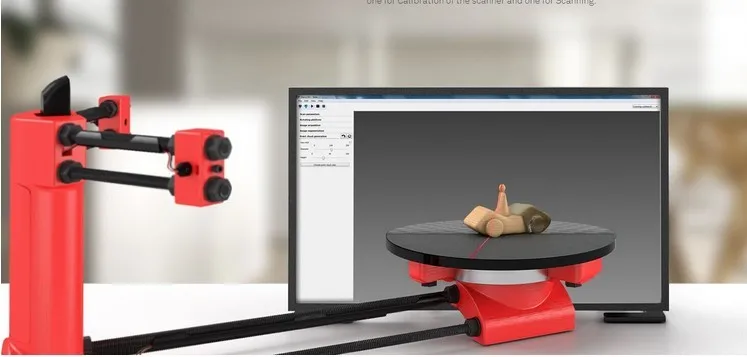
Assembly of the structure: prepare lasers part
Another problem is that you can probably find a low cost laser that don’t fit on orginal holder.
The common laser is 12mm laser.
You can find laser here AliExpress - eBay
So you must use this 3D printed variant.
Another problem is to stop the rotating part, I think the better solution is to use a rubber band, as you can see in the pictures.
Original laser holder (For the laser I posted use previous file)
Ciclop 3D scanner prepare laser parts- Printed part of laser holder
- M3 x 10 mm screw
- M3 nut
- Allen wrench
Insert the nuts into the side holes. They must enter very fair. If not, file the gaps a bit.
Ciclop 3D scanner prepare laser parts assemblyStructure assembly: adjust lasers parts
Ciclop 3D scanner adjust laser parts- Basic structure assembled
- Laser holder just assembled
- Washer M8
- Nut M8
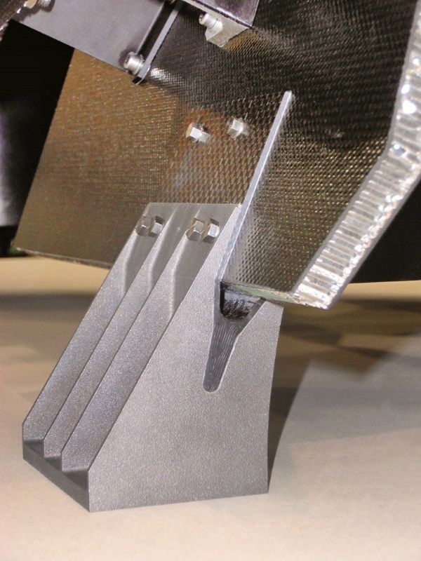
Assembly of the structure: prepare socket piece
Shaft coupling
Ciclop 3D scanner prepare socket piece parts- Printed part of motor-disc socket
- M3 X 10 mm screw
- M3 nut
- Allen wrench
Frame assembly: prepare Nema motor
Ciclop 3D scanner prepare nema motor parts- Nema motor (1.
 7A 1.8 deg / step)
 - Structure already assembled
- M3 x 10 mm screw
- Allen wrench
Assembly of the structure: join the socket and the disc
Ciclop 3D scanner join the socket and the disc parts- Socket assembled
- Main structure
- Disk structure
- Allen key
Assembly video
There are a lot of video also, the official one is this.
Documentation
Thanks
- Ciclop 3D scanner: component printing and assembly
- Ciclop 3D scanner: production and assembly of the control PCB
- Ciclop 3D scanner: assembling electronic and wiring
- Ciclop 3D scanner: componens testing and calibration
Support forum
Spread the love
Ciclop desktop laser 3D scanner user manual in English
- Live Chat
-
- Message Us
- Presale Live Chat
- Submit a Ticket
- One stop service: solve all your problems
- Orders Tracking and shipped out notification
- More campaigns, even more discounts!
- Need help before making an order?
- Chat with us in real-time.
- For Aftersale issues, just submit a ticket. We will reply within 24 hours.
- Multi-language service
- 24/7 support available
- Save $3 with App
-
Download App!
Save $3 with App & New User Only
Hi!Log OutLog InSIGN UP
Search
Home > Download > Ciclop desktop laser 3D scanner user manual in English
This is Ciclop desktop laser 3D scanner user manual in English, it contain: 3D Scanner installation, Operate software, Control, Calibration, Scanning workbench, Horus Guide to post processing of the point cloud, Assembly of the Electronics, Horus Guide for Optimum Scanning.
Contents in this user manual:
1. Ciclop Desktop Laser 3D Scanner installation
2. Operate software: Horus
3. Control, Calibration, Scanning workbench
4. Horus Guide to post processing of the point cloud
5. Assembly of the Electronics
6. Horus Guide for Optimum Scanning
For Gearbest customers: If you've purchased Ciclop Desktop Laser 3D Scanner from us and still have problem after using the firmware, please do not hesitate to get in touch with us. Just fill in the ticket with your questions at our Support Center and send it to us. We will do our best to deal with your problem as soon as possible. We are always happy to help.
| ● Over 300,000 products ● 20 different categories ● 15 local warehosues ● Multiple top brands | ● Global payment options: Visa, MasterCard, American Express ● PayPal, Western Union and bank transfer are accepted ● Boleto Bancario via Ebanx (for Brazil) | ||
| ● Unregistered air mail ● Registered air mail ● Priority line ● Expedited shipping | ● 45 day money back guarantee ● 365 day free repair warranty ● 7 day Dead on Arrival guarantee (DOA) |
Prev article:Dibea C17 2-in-1 wireless vacuum cleaner user manual in English
Next article:breo iPalm520S wireless electric hand massager user manual in Chinese and English
Download Here:
Ciclop desktop laser 3D scanner user manual in English
You might also like:
HOT
-
MXQ 4K TV box ROM firmware pack
2017-05-03 by GB Blog Official
This is firmware pack for MXQ 4K TV box.
 Download here for free as you need once you are logged in.
 -
7018B Bluetooth car MP5 player firmware pack
2018-09-07 by Steve Lowry
This is 7018B Bluetooth car MP5 player firmware pack, you can download here for free as you need once you log in your Gearbest account.
-
7012B Bluetooth car MP5 player firmware pack
2018-09-07 by Steve Lowry
This is 7012B Bluetooth car MP5 player firmware pack, you can download here for free as you need once you log in your Gearbest account.
-
DZ09 Smart Watch Phone Firmware Pack
2017-03-15 by Ingrid Wilhelmina
This is ROM Firmware Pack for DZ09 Smart Watch Phone. Download here for free as you need once you are logged in.
-
M4 Smart Bracelet User Manual in English
2019-07-29 by Lydia Scott
This is M4 Smart Bracelet user manual in English, it contains the requirement of phones, before use, APP download, bind APP, how to use the M4 Smart Bracelet, smart band operation, and functions.

-
H96 PRO TV box ROM firmware
2018-05-14 by Adeline Belluz
This is firmware pack for H96 PRO TV box. Download here for free as you need once you are logged in.
Related Products
DIY Cyclops assembly and laser scanning software
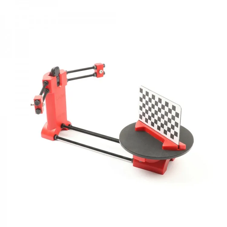
Greetings to all. Today is a small review of the Ciclop desktop scanner.
Once again, the store offered to take something for review. Since I have long been interested in the question of using this thing for the needs of decorative 3d printing, I chose a scanner.
So, the scanner itself was developed by the Spanish company BQ, which has now ceased its support (supposedly due to Chinese fakes, but it is doubtful. Now the American CowTech also sells this scanner. The source codes for 3d printing of parts of the scanner are freely available at Thingiverse (there are also links to software and electronics).0003
Links to complete documentation kits:
www. cowtechengineering.com/downloads
www.bq.com/ru/support/ciclop/support-sheet
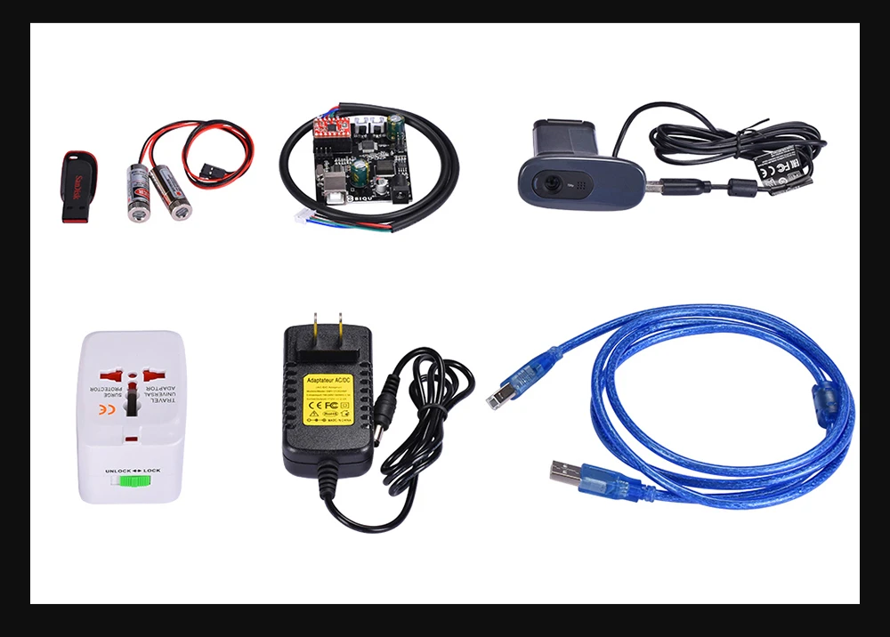
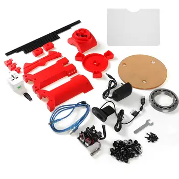
In the kit we have such a “loose”:
The assembly is simple, however there are several points:
1. It is not worth rushing to tighten all the nuts - you still have to adjust the geometric dimensions - the convergence of lasers in the center of the site, the distance to the turntable.
2. In my stand, the camera “dangled” a little, by a fraction of a millimeter - but that was enough to skew the picture. Eliminated by laying foam material.
4. The turntable was transparent and uncoated (as in the original) - I painted it with plastidip.
5. Check the calibration checkerboard patterns. I don’t know how they printed the one from my kit - but the proportions of the squares were violated. I took it from the Internet and reprinted it myself.
6. The focus of the camera is not adjusted to the distance to the platform. He removed the cover and twisted the focus in place.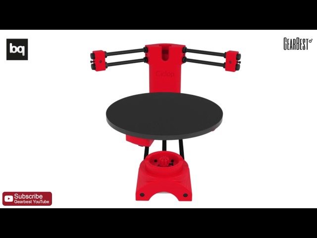
88. The economy is managed by the "native" Horus software from BQ.
After assembly, the scanner went through calibration procedures in the native Horus software.
Since by this point I already knew that the quality of scanning is very much dependent on the quality of lighting (stability, diffuseness, color temperature), I took care of having a small lightbox in advance in order to at least provide more or less comparable conditions for samples.
Having selected the "candidates" for the samples, I got ready.
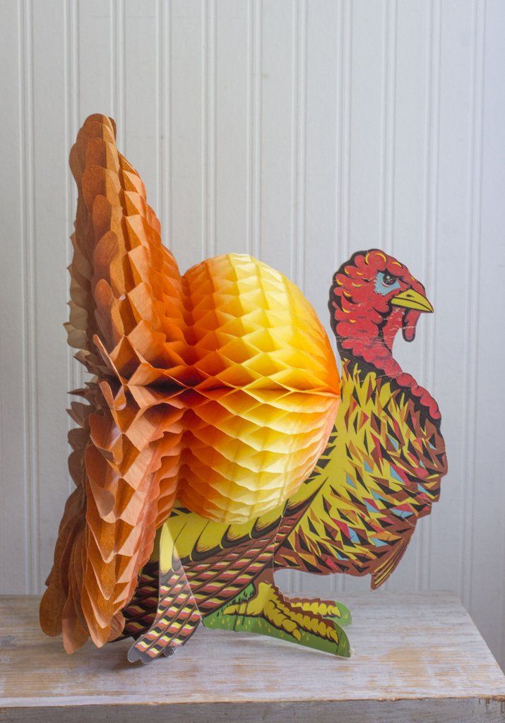
Requirements for the object are stated as follows:
1. The object must be larger than 5x5 cm but smaller than 20x20 cm
2. The object must be opaque and still
3. The object must weigh no more than 3 kg
Difficult to scan:
1. Shiny, luminous objects
2. Too dark objects
3. Objects with a blurred surface (eg soft toys)
The result of the scan is a cloud of points in PLY format (which must then be converted to a surface).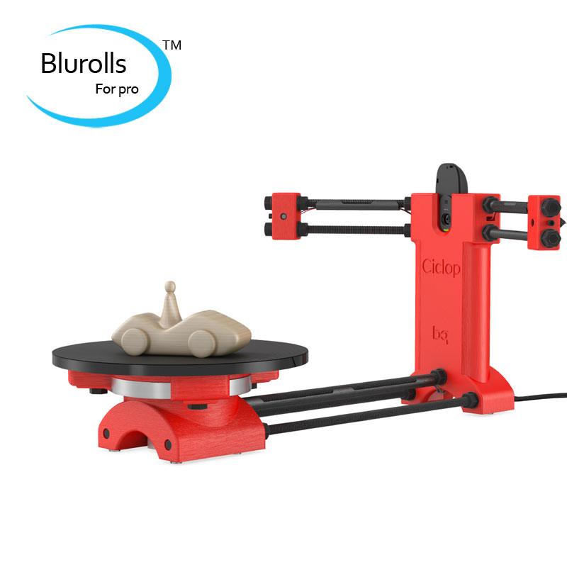 Here is a guide for post-processing the cloud and preparing the STL file.
After reading the scan optimization guide, I decided to try with a simple cylindrical object.
After several attempts, I was convinced that I had a common problem - mismatches in the point clouds from the right and left lasers, and the issue with proportions.
Nothing worthwhile about this except for trying to calibrate the webcam settings (they are not calibrated when the calibration wizard is running) could not be found (a dude named Jesus from BQ support has not answered questions for a long time). To do this, you need to take several shots with different positions of the calibration table. Done. The situation has improved, but not completely.
I had to manually edit the calibration file (calibration.json in the Horus-a folder) and by trial and error, scanning a cylindrical object, to achieve the coincidence of the clouds.
And everything seems to be ok:
But no - on complex objects, cloud fragments still sometimes do not coincide, moreover, many "blind" zones are formed:
impossible, at least with regular lasers.
You can, of course, continue experimenting with scanning with individual lasers and trying to combine all this economy in third-party software, and then try to bring it into a viable form for STL.
All this is reminiscent of a joke about boats in bottles.
-How do you make boats in bottles?
-I put sand, silicate glue, sticks into the bottle and shake it.
It turns out all sorts of shit, and sometimes boats.
In general, I realized that I am not an adept of such creativity, and I have a suspicion that it is easier to model objects from scratch that are easier for a scanner.
And complex ones - the scanner cannot cope with complex ones in normal mode, two lasers are not enough for it - blind spots remain. To fix this problem, you need to scan in other positions and then again suffer with the combination of clouds. No thanks.
As a result - the thing will fit only for learning the basics of laser scanning, for something more - absolutely useless.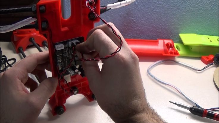 No, of course, you can get something with outlines similar to the original model, but on this (and this, taking into account all the tambourines with cloud processing), that's it. No wonder the Spaniards abandoned this case.
The store made sure - in the description it is honestly stated that the result depends on the position of the planets and the mood of Aunt Sonya from the third floor. Open source and all that, let's dance together. No thanks.
Conclusion - don't take it, but if you're into extreme hunting, assemble it yourself from the same material that your friend from the joke makes boats from.
Product for writing a review provided by the store. The review is published in accordance with clause 18 of the Site Rules.
Ciclop 3D scanner. With my own hands.
Ciclop 3D Scanner by bqLabs
http://www.bq.com/gb/products/ciclop.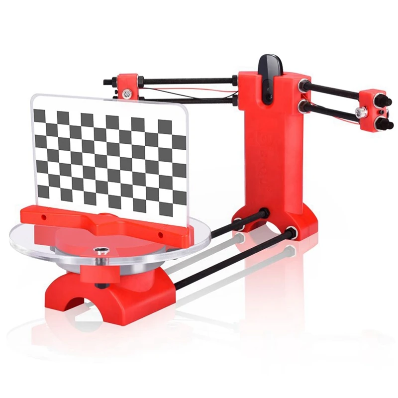 html
html
http://diwo.bq.com/en/ciclop-released-2/
Firmware code https ://github.com/bq/horus-fw
Firmware HEX http://diwo.bq.com/en/horus-fw-released/
Firmware Hex Upload http://russemotto.com/xloader/
Experience Cyclops buildings "Ciclop 3D scanner - the devil is in the details!"
Discussion of my research on TriDeshnik http://3deshnik.ru/forum/viewtopic.php?f=8&t=15
Now you need to smartly split the part camera-holder.stl
Cleaned it from supports. You can download a blank part. While I will cut into three parts for twisting with screws.
Cut into three parts for twisting with M3x10 screws. Download archive with stl models.
General connection diagram of the stepper motor driver
Connection to Arduino Nano
Lasers connect D2+GND, D3+GND
General assembly scheme
Table assembly
3 - M3x10 screw 5 pieces
4 pieces - M3 nut 1 piece 6 - M380.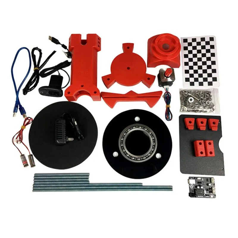 Screwed into the disc (10). You can take the M8 screw "in the secret" and screw it in from top to bottom, tightening it with a nut at the bottom.
Installation and fixation of lasers
2 - M3x10 laser housing fixing screw, 2 pcs
3 - M3 nut 2 pcs
4 - Laser 2 pcs
Studding
1 - M8x400 threaded stud 2 pieces
2 - M8 nut 28 pieces
3 - M8 washer 18 pieces. Laid between the nut and the plastic part
4 - Cable duct. Can be replaced with electrical tape
5 - M8x292 threaded stud 1 piece
6 - M8x170 threaded stud 4 pieces. Hold lasers. I think it's wiser to put thinner studs here
7 - Cable channels 3 pieces. Can be replaced with duct tape or heat shrink
Checkerboard pattern holder assembly
2 - M3 nut 2 pieces
3 - M3x10 screw 2 pieces
4 - plywood cardboard
5 - chess paper sticker. pdf, svg
Assembly video
Until I started to assemble myself, it seems to me that this is enough for the assembly. In the course of the infa will change and be supplemented.
Assembly
Brutal bearing
Paste the leather on the table
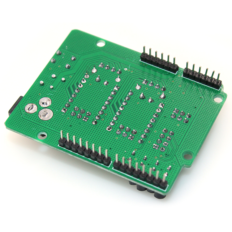
Soldering wiring on the driver
As a result, I have to do it on Arduino Uno, since I miscalculated with Nanami.
I've already stumbled on connectors in UNO;)
We've arrived. Horus does not see UNO's COM port.
And in the device manager, instead of Arduino UNO, it says Ch440. It looks like you have to reflash the bootloader.
Here is the correct scheme for flashing UNO (Duemilanova) via MEGA 2560. Only I have a 100 microfarad conduit (probably will do). I will check.
Bootloader firmware steps in Arduino UNO ( Duemilanova), via Arduino Mega:
[ Click to read ]
step 1 - Nothing is connected to the Mega, except for the USB cable. Launch the Arduino IDE. We set the Mega parameters: Board, Processor, Port.
step 2 - Go to menu File -> Samples and click ArduinoISP. The sketch of the ArduinoISP programmer is loaded into the editor. Press the round button with an arrow to the right "Upload" and upload the sketch to Mega.
step 3 - Disconnect Mega from everything and connect to UNO (Duemilanova) according to the scheme (above). And we also stick a capacitor (I have 100 microfarads). We connect Mega via USB to the computer.
step 4 - Now in the Arduino IDE set the parameters for UNO (Duemilanova): Board, Processor, Port
step 5 - Go to Tools -> Programmer and click on "Arduino as ISP". Now our Mega has become a programmer.
9009Step 4 5 - Flashing the bootloader on UNO (Duemilanova) via Mega. In the Tools menu, click "Burn bootloader". Both boards should have blinking LEDs. Ready. We disconnect everything.
I tried to reflash Bootloader according to the scheme in UNO.