Calibrate z axis 3d printer
How to Calibrate Your Z-Axis on Your 3D Printer – Ender 3 & More – 3D Printerly
Calibrating the Z-axis on your 3D printer is a good way to ensure you are getting dimensionally accurate 3D printers, as well as creating better quality models. This article will take you through the calibration process for your Z-axis.
To calibrate the Z-axis on your 3D printer, download and 3D print an XYZ calibration cube and measure the Z-axis with a pair of digital calipers. If it doesn’t have the correct measurement, adjust the Z-steps until the measurement is correct. You can also calibrate your Z offset using a BLTouch or by ‘live-leveling’.
There’s more information that you’ll want to know for calibrating your Z-axis, so keep on reading for more.
Note: Before you start calibrating your Z-axis, you have to make sure your printer is in order. Here are a few ways to do this.
- Make sure all the belts are properly tensioned
- Check and see if the print bed is leveled
- Make sure your Z-axis isn’t slipping or experiencing binding
- Calibrate your extruder e-steps
How to Calibrate Z Axis Steps on a 3D Printer (Ender 3)
An XYZ Calibration Cube is a model with precise dimensions you can print to know if your printer is correctly calibrated. It helps you see the number of steps your motor takes per mm of filament it prints in all directions.
You can compare the expected dimensions of the cube with its actual measurements to know if there is any dimensional deviation.
You can then calculate the proper Z-steps/mm for your printer with these values. Check out the video below to see how you can calibrate your 3D printer’s stepper motors.
Step 1: Get Your Printer’s Current Z-Steps/mm
- If you have an Ender 3 or similar printer running the Marlin firmware, you can get it directly via the display on the machine.
- Navigate to Control> Motion > Z-Steps/mm. Note down the value that is there.

- If your printer doesn’t have a display interface, you can still get the Z-Steps/mm, but with a more complex method.
- Using control software like Pronterface, send the G-Code command M503 to your printer – it requires some setup to get started.
- It will return some lines of code. Look for the line that starts with echo M92.
- Look for the value starting with Z. This is the Z-steps/mm.
Step 2: Print the Calibration Cube
- The Calibration Cube’s dimension is 20 x 20 x 20mm. You can download the XYZ Calibration Cube from Thingiverse.
- When printing the Calibration Cube, don’t use a raft or a brim
- For the best results, slow down the print speed to around 30mm/s and reduce the layer height to around 0.16mm.
- When the cube finishes printing, remove it from the bed.
Step 3: Measure the Cube
- Using a pair of Digital Calipers (Amazon), measure the Z-Height of the cube.
- Measure it from top to bottom and note the measured value down.
Step 5: Calculate the New Z Steps/mm.
- To calculate the new Z-Steps/mm, we use the formula:
(Actual Dimension ÷ Measured Dimension) x Old Z Steps/mm
- For example, we know that the cube’s Actual Dimension is 20mm. Let’s say the printed cube, when measured turns out to be 20.56mm, and the old Z steps/mm is 400.
- The new Z-steps/mm will be: (20 ÷ 20.56) x 400 = 389.1
Step 6: Set the Accurate Value as the Printer’s New Z-Steps.
- Using the printer’s control interface go to Control > Motion > Z-steps/mm. Click on Z-steps/mm and input the new value there.
- Or, using the computer interface, send this G-Code command M92 Z [Insert accurate Z-steps/mm value here].
Step 7: Save the New Z-Steps Value to the Printer’s Memory.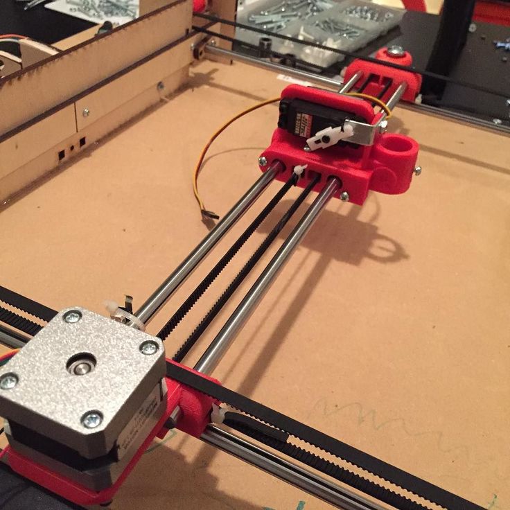
- On the 3D printer’s interface, go to Configuration/ Control > Store memory/settings. Then, click on Store memory/settings and save the new value to the computer memory.
- Using G-Code, send the M500 command to the printer. Using this, the new value saves to the printer’s memory.
How Do You Calibrate Z Offset or Z Height on a 3D Printer
If you do not have a BLTouch, you can still calibrate your printer’s Z offset with a bit of trial and error. All you have to do is print a test print and make adjustments based on the quality of the print’s infill in the middle.
Here’s how you can do this.
Step 1: Make Sure Your Print Bed is Leveled Correctly and Clean.
Step 2: Prepare the Model for Printing
- Download the Z Offset Calibration Model by scrolling down to the ‘Model files’ STL section – there is a 50mm, 75mm & 100mm square option
- You can start with 50mm and decide to move up if you need more time for making adjustments.
- Import it to your chosen slicer and slice the file
- Save the file to an SD card and load it onto your 3D printer
- Begin printing the model
Step 3: Evaluate the Model as it Prints
- Check the infill of the model and how it’s extruding to determine the adjustments that need to be made.
- The objective of this print is to get the first layer as smooth and level as possible.
- If the gaps in the infill are significant and there are low spots between them, reduce your Z offset.
- If the lines in the print are smooshed together and do not retain their shape, increase your Z offset.
- You can change the Z offset in intervals of 0.2mm until you reach the desired change – do keep in mind that the adjustments to the Z offset can take a few extruded lines to show its effects.
Once the top layer is smooth without any smooshing, gaps, valleys, or ridges, you’ve got the perfect Z offset for your printer.
How To Calibrate Your Z-axis Using a BLTouch Probe
The Z offset is the Z distance from the printer’s home position to the print bed. In a perfect world, this distance should be set to zero.
However, due to inaccuracies in the print setup and the addition of components like a new print surface, you might have to adjust this value. The Z offset helps compensate for the height of these objects.
A BLTouch is an automatic leveling system for your print bed. It can help measure the exact distance from your nozzle to your bed and help compensate for any inaccuracies using the Z offset.
The video below takes you through the process of calibrating your Z offset on an Ender 3 V2 with a BLTouch. V3.1 (Amazon).
Let’s see how you can do this.
Step 1: Heat the Build Plate
- If your printer runs the Marlin firmware, navigate to Control > Temperature> Bed Temperature.
- Set the temperature to 65°C.
- Wait for about 6 minutes for the printer to reach this temperature.
Step 2: Auto-Home Your Printer
- On your control interface, click Prepare/ Motion > Auto-home.
- If you’re using G-Code, you can send the command G28 to your printer to auto-home it.
- The BLTouch will scan the print bed and try and determine where Z = 0
Step 3: Find the Z Offset
- The BLTouch will be at a distance of about Z = 5mm from the printer’s bed.
- The Z offset is the distance from where the nozzle is currently to the print bed. To find it, you’ll need a piece of paper (a sticky note should do just fine).
- Place the piece of paper under the nozzle
- On your printer’s interface, go to Motion > Move axis > Move Z > Move 0.
 1mm.
1mm. - On some models, this is under Prepare > Move > Move Z
- Gradually reduce the Z value by turning the knob counter-clockwise. Turn the Z value down until the nozzle grips the paper.
- You should be able to pull the paper out from under the nozzle with some resistance. This Z value is the Z offset.
- Note down the Z value
Step 4: Set the Z Offset
- After finding the value for the Z offset you may need to input it into the printer. In some cases, it will automatically save.
- ON newer models, go to Prepare > Z offset and input the value you’ve gotten there.
- On older models, you can go to the Main screen > Configuration > Probe Z offset and input the value.
- If you’re using G-Code, you can use the command G92 Z [input the value here].
- Note: The square brackets in front of the Z offset is very important.
 Don’t leave it out.
Step 5: Save the Z Offset to the Printer’s Memory
- It’s important to save the Z offset to avoid resetting the value when you turn off the printer.
- On older models, go to Main > Configurations > Store Settings.
- You can also end the G-Code command M500.
Step 6: Re-Level the Bed
- You want to manually re-level the bed one last time so that all the four corners are at the same height physically
Well, we’ve reached the end of the article! You can use the methods above to configure your 3D printer Z-axis so you can get accurate prints consistently.
Just make sure other parts of your printer, like the extruder’s flow rate, are in proper order before making these adjustments. Good Luck!
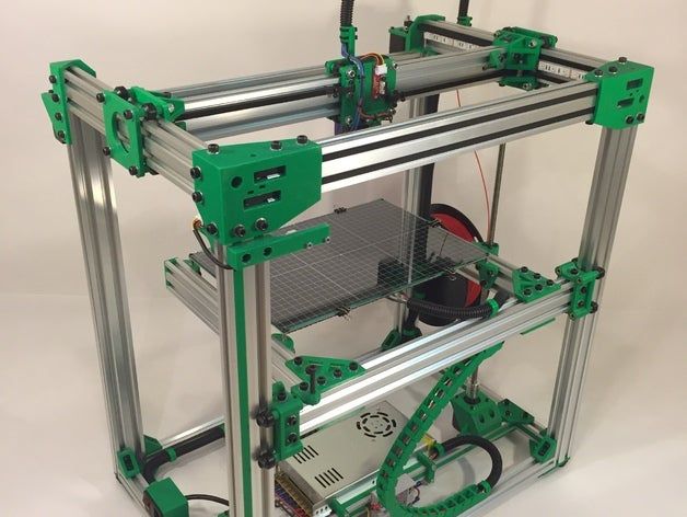
3D Printer – X,Y and Z Axis Calibration – www.muckypaws.com
A common mistake when calibrating your printers X, Y and Z Axis is to print a 20mm calibration cube from Thingiverse, measure the dimensions with Callipers and make adjustments to your step rates.
I too was simply following instructions… Whilst that method may appear to work and it did print a perfect 20mm cube, it doesn’t take into account the materials expansion/contraction ratio.
I’m informed by the professionals the correct method is to measure the actual head movement and calculate your steps accordingly.
Achieving this is straight forward. Make sure your printhead has cooled down and attach a pencil. I used an elastic band, though you may need to get creative with your printer. Clip a piece of paper to the print bed and enter your printers Axis movement menu.
From the printer menu, I requested an X Movement of +100mm and a Y Movement of +100mm.
Using digital callipers, measure the actual distance travelled by the print head.
For the Z-Axis, I measured the current height from the bed to a fixed point underneath the print head before zeroing the callipers then requesting a movement of +100mm taking the same measurement. Though you can clip paper to the frame and move the pencil to the Z Axis and record movement that way.
To calculate your eSteps, the equation is simple,
(Amount Requested / Actual Amount) X Current Steps Value = New Steps Value
How to calculate New Steps ValueFor example, if I requested 100mm on the X-Axis and the printer moved 98.5mm then the calculation would be (100/98.5) x 80.12 = 81.34, therefore you would enter 81.34 in your printers X-Steps set up.
Repeat the exercise again until your printer is moving the required distance.
And that’s pretty much all there is too it!
Clip Paper to the Print Bed and Attach a Pencil. Current Steps Configuration Screen Final Calibration, Spot on! Print an X, Y, Z Calibration CubeLike this:
Like Loading...
3D Printing, Personal, Tech
3D Print, Calibration, Geeetech, How To, XYZ
Translate
Search for. ..
..
Follow www.muckypaws.com on WordPress.com
Follow Blog via Email
Enter your email address to follow this blog and receive notifications of new posts by email.
Email Address:
Advertisements
Categories
CategoriesSelect Category3D Printing65028BitairlinesAlgarveAmstradAntiguaAppleAppsArcadeAustraliabad customer serviceBakingBereavementBratislavaBudapestCairoCambridgeCancerCaribbeanCelebrationscinemaComponentsComputers and InternetCopenhagenCustomer SatisfactionCustomer ServiceDallasDatingDiabetesDIYDominican RepublicEducationEgyptEuroMillionsFlightAwareFranceFreeFreewareGameBoyGames ConsoleGamingGDPRGermanyGreaseWeazleGriefHackingHATHong KongHospitalHowToIbizaIndiaInterviewiOSItalyJapanKangaroo IslandLondonLotteryMacMac OSXMacOSMadridManic MinerMedicalMiscellaneousModsNHSNintendoobservationOctoPrintOSXParisPCPC SoftwarePersonalPhotographyPhotoshopPiPiHolePortugalPragueProjectsPuzzleRamblingsrantRaspberry PiRecipesRepairsRetroRetro GamesRetropieRomeScamSecuritySilverstoneSingaporeSlovakiaSmith and BrooksSmithAndBrooksSoftwareSpainSTLTeam OutingsTechTouristTravelUKUK LotteryUncategorizedUnityUSAViennaWembleyWidowedWindowsXCodeXmasYouTubeZX SpectrumAxle calibration
Recently (well, about once a week for sure) I very often describe a simple way to calibrate the axes, which is why I decided to make a separate post so that novice makers do not ask questions, but do a search on the site.
So you bought/assembled/built the printer, uploaded the firmware and here it is the first print, but upon examination it turns out that the printer along the axes does not print the dimensions that are indicated in the model and should be on the printout.
Clearly the axes need to be calibrated.
There are several ways to calibrate axes.
The first method is to correct the steps in the firmware.
Install and run the Arduino IDE in which we open our firmware. On the configuration.h tab we find the line:
#define default_axis_steps_per_unit {100,100,3200,80}
These numbers need to be changed to your own. But where do you get these numbers?
To do this, you first need to print the part (usually a test cube) with known parameters, for example, this 3D model “Test cube 20x20x10mm” (the link is the very first one that came across in the search) the most important thing is to know the dimensions of the model, and you can print anything whatever.
So we have a printout with dimensions 22,23,11. We consider the usual proportion:
Along the X axis
22 - 100 (the first digit from the firmware) firmware)
20 - y
y = 20*100/23 = 86.96
on the axis Z
11 - 3200
10 - Z
Z = 10*3200/11 = 2909.09
Fourth digit is an extruder is an extruder. , we consider its supply as follows:
For the extruder motor to start moving, the nozzle must first be heated to operating temperature. If you have a bowden, then you need to pull the bowden tube out of the hotend and make a mark on the filament with a marker or something else, the main thing is that it be noticeable. In any program for working with the printer (Repeater, PronterFace) or from the menu of the printer itself (for example, the 12864 display with Russian language - Actions - Movement along the axes - Extruder) extrude the thread by 50-100-150-200 mm (to choose from than more topics can be measured more accurately). After that, we measure how much the thread came out, for example, we squeezed out 200 mm of thread, and we got 190 mm. Again, we count in proportion
190 - 80
200 - Z
Z=200*80/190=84.21
This adjustment must be done several times to be accurate.
Now we have a line
#define default_axis_steps_per_unit {90.91,86.96,2909.09,84.21}
100/22.20*100/23.10*3200/11.200*80/190} the printer will calculate everything by itself.
After that, we flash our board with new data and again print a test cube, measure and correct if necessary. It is better to make a few adjustments so that the numbers are more accurate.
During these adjustments, it is imperative that the feed rates of the axes and the extruder are correct, otherwise you will always get different numbers.
The second way - Correcting the steps on the printer display (for example, 12964 Russian)
Go to the menu item - Settings - Mechanics, scroll down and find the lines:
X step / mm - 100
Y step / mm - 100
Z step / mm - 3200
E step / mm - 80
Accordingly, we change these numbers to those already calculated above (we try to get exact numbers from the encoder)
X step/mm - 90. 91
91
Y step/mm - 86.96
Z step/mm - 2909.09
E step/mm - 84.21
Since the firmware has write protection enabled in EEPROM, then saving will fail and you still need to do a flashing.
Third method - Through the RepetierHost program Install and run the program, connect the printer (the printer should connect and give out all the temperatures and something like ready) Go to the Configuration tab and open the EEPROM configuration.
Here again we see the numbers that are written in the firmware. We change the numbers to ours and save the EEPROM.
The RepetierHost program also has a Tools menu item - there you can calculate the numbers calculated above knowing several printer parameters (Motor pitch, pitch divider, belt pitch, number of teeth on the pulley and for the lead screw motor step, pitch divider, lead screw pitch, gear ratio) but often these parameters are unknown to the user, so I do not consider it.
Again, I note that if write protection is enabled in the firmware in EEPROM, then saving will fail.
There are many more programs to correct these numbers, but the principle is the same.
Thank you for your attention, I accept criticism and praise in the comments :)
PS I wanted to put pictures, but something suddenly became lazy, everything seems to be clear even without pictures.
Subscribe to the author
Subscribe
Don't want
54
How to calibrate a 3D printer in 5 steps・Cults
The first 3D printer was developed in the 1980s by Charles W. Hull, but the technology only became popular in the early 2000s. Since then, 3D printing has come a long way and is used all over the world for personal and industrial applications.
3D printing enthusiasts will attest that it takes a long learning curve to make good use of this technology and related software. One of the hardest parts of this learning curve is machine calibration. Here we will cover the basic calibration procedure required for 3D printers. This article is written from the point of view of simple and reusable Printrbot and assumes that the user has a digital caliper, ruler, ribbon, and thread. If the reader does not use Printrbot simple and Repetier, then there is no problem, any combination of printer and software will do.
Open Repetier, connect the printer and select the manual tab. Select the toggle button with simple mode disabled and enter "M501" in GCode. Press the Enter key and scroll until you find a code that looks like "echo": M92 X__ Y__ Z___ E__.".
Pay special attention to this line of code, as it will be important in the future. to the side and place a piece of tape on the printer bed, parallel to where it will not move when you move the X axis. Mark the tape where the X axis currently points.
Using the Repetier program, instruct the printer to move the X axis starting at the 70mm mark, and make another mark at the end of the X axis. The printer has simply moved to where it thinks 70mm is. Now, using a caliper, measure the distance between the two marks to determine the actual travel distance.
A new M92 value needs to be found, using the current M92 value recorded in step 1. This can be achieved using the following equation. After calculating the new value M92 for the x-axis, it must be entered in the G-code.
New M92 value = desired travel/actual travel * actual M92 value.
The process of calculating the Y-axis is the same as calculating the M92 actual value for the Y-axis. Note where the Y-axis starts, enter a value for its offset, and note where the Y-axis ends. Using a caliper, you can determine the actual distance travelled. Using the same equation, a new M92 value can be calculated and entered into GCode.
New M92 value = desired travel/actual travel * actual M92 value.
The Z axis is much easier to calculate with a ruler than with a caliper. To get started, simply specify the x, y, and z axes and position the ruler parallel to the plate. Select a point on the print shoulder along the Z axis and measure the distance from the printing plate to that point. Now, as before, enter a value for the x-axis offset and measure how much it has moved. Formula for determining the new value of M92 for the Z axis is slightly different from the other two.
Input measurement/actual measurement * Old M92 value = New M92 value.
Enter this value in the GCode for the Z axis.
This is the last item to check in the calibration process. To calibrate an extruder, determine how much filament comes out of the extruder. To begin, heat the hot end to the suggested temperature and make a mark on the thread about 3 cm from the entry point. Command the printer to extrude 10mm of filament and take a measurement to determine the distance between the two points. If the distance is 10 mm or any other value is entered, then the extruder is calibrated. Otherwise, a new value of E M9 must be calculated2 and enter it into GCode. This value can be found using the formula below.