Blender 3d printing toolbox
3D Print Toolbox — Blender Manual
Reference
- Category
Mesh
- Description
Utilities for 3D printing.
- Location
3D Viewport ‣ Sidebar
- File
object_print3d_utils folder
- Author
Campbell Barton
Installation
This add-on is bundled with Blender.
Open Blender and go to Preferences, then the Add-ons tab.
Click Mesh then 3D Print Toolbox to enable the script.
Description
Blender can be used to created meshes for 3D printing. Meshes exported from Blender are usually imported into a piece of software takes the mesh and “slices” it into paths that the 3D printer can execute. An example of such Slicer software is Cura.
In order to correctly slice a mesh, it needs to be “watertight”, meaning that the surface is closed everywhere. Additionally, there should be no edges or faces sticking out. 3D Print Toolbox helps you analyze problems in your mesh that could cause slicing issues.
It can be found in 3D Viewport ‣ Sidebar ‣ 3D-Print, when a mesh is selected.
Analyze
Statistics
By clicking either Volume or Area, the volume or area of the mesh is calculated and shown.
Checks
The Checks panel.
A number of different checks can be performed to analyze in which ways your mesh might be invalid for use with a Slicer.
Upon execution of one of the checks, the Result field shows which, if any, parts of your mesh are invalid.
When in Edit Mode, clicking these results selects these parts of your mesh. You can use View Selected Backslash to focus on these parts.
Although Slicers are becoming increasingly tolerant when it comes to “tidiness” of meshes, it is always worth trying to provide as clean a mesh as possible.
- Solid
Checks for Non-Manifold edges and Bad Contiguous edges.
Edges should connect to exactly 2 faces. In it connects to only one, it means there’s a hole in the mesh. More is also not allowed. These edges are considered Non-manifold. If one of the faces’ normals is pointing in a different direction than its neighbors, its edges are marked as “Bad Contiguous”.
In this screenshot, the left shape has a hole, and the right shape has one of its faces flipped.
Left, marked in blue: Non-manifold edges. Right, marked in red: Bad contiguous edges.
- Intersections
These two cubes have intersecting faces. A Boolean modifier would help in this example. It’s worth noting that some slicer applications can deal with this, so it’s not always required to resolve this issue.
- Degenerate
Faces and edges which have 0 area or length, are considered degenerate. In this example, the top face of a cube has been scaled down to 0, but have not been merged. A Merge ‣ By Distance would resolve this issue.
There’s a hidden face here.
- Distorted
The vertices of a quad or ngon can be folded in such a way that the face is not flat. In practice, quads are rarely ever flat. When exporting, these faces are converted to triangles. If the surface is excessively deformed, this can result in unexpected shapes.
In this example, a quad has been folded into a saddle-like shape. This triggers the Distorted check. It would be best to triangulate by hand here.
This quad can triangulate in unexpected ways.
- Thickness
Faces that form very thin geometry might be missed entirely by the slicer. Such faces are marked as Thin.
- Edge Sharp
Similar to Thickness, sharp edges can thin pieces of geometry which might be missed by the slicer
- Overhang
As 3D printers can’t print in mid-air, parts of the model which overhang will not print correctly. In practice, slicers can add additional material, support, to anticipate for overhanging layers.

- Check All
Performs all of the above checks at once. In this example, Suzanne shows quite a few problems. This is because the eyes are separate parts, and the sockets have holes. This makes the mesh not Solid and Intersecting. Some of the faces are Distorted.
Clean Up
- Distorted
Triangulates the faces which are considered Distorted, as explained above.
- Make Manifold
Attempts to fix various problems which might make a mesh non-manifold, such as by fixing bad normals, filling holes, and removing empty edges and faces.
Transform
Scale To
- Volume
Scales the model to an exact given volume.
- Bounds
Scales the model so that the biggest axis of the objects bounds (or dimensions) match the given value.
Export
Provides quick access to Blender’s object exporting operators found in File ‣ Export.
How To Use The 3D Print Toolbox Add On? – blender base camp
One of the fastest-growing industry subsets today is the field of 3D printing, the ability to design an object virtually and then construct that object as a single piece using specialized tools and software. Blender is capable of creating 3D printable objects and then sending them to an application used for the 3D printing process. To make life easier, Blender has an add-on for helping to construct models for the purpose of 3D printing.
To activate the Print Toolbox Addon, first, go to Edit > Preferences > Add Ons, and in the search bar in the top corner type in print toolbox, making sure the tickbox is enabled before closing the preferences panel. To locate the toolbox, press the N key on the viewport to open the side panel, and select the print toolbox tab.
This is perhaps the single most important add-on that you can use for 3D printing in Blender, but what exactly does it do and how can it help to construct printable 3D objects?
What Is The 3D Print Toolbox Actually Designed To Do?
The 3D print toolbox is designed primarily to identify geometry that is likely to cause issues with the printing process.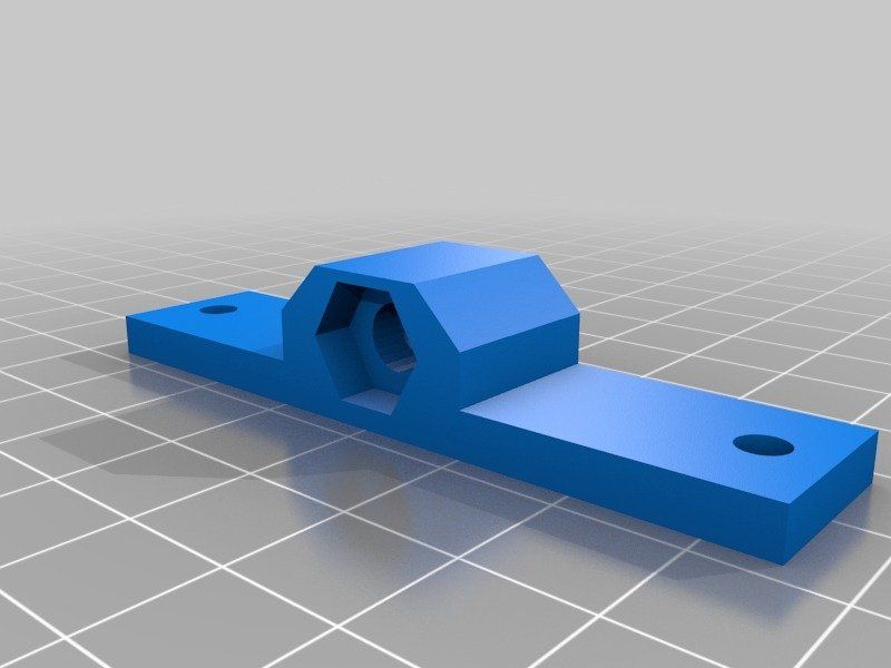 3D printers are limited in their capabilities and so as the designer of the object you need to ensure that the model falls within these limitations. An example of such a limitation is the size of the model, as each 3D printer is capable of producing objects in a certain size range.
So the 3D print toolbox is able to accurately calculate both the area and volume of a selected model, which are the parameters used for defining an object’s size in 3D printing.
Equally as important is the ability to find geometry that is not suitable for a 3D printable model. This comes in several different forms and so the print toolbox is able to find which faces effectively fail specific tests. An example of this is finding overhanging faces that are not supported by the rest of the model.
Toolbox LocationWhile the primary purpose of the print toolbox is to identify problem areas of the model, it is also capable of cleaning up your geometry with the help of a couple of simple tools. However, it will only fix the geometry that it finds issues with, and we suggest other methods as well for actually fixing these issues, such as removing duplicate vertices.
Get 30 Days Free Access To The Blender Course Library
Why Do We Need To Use The Add On To Identify Issues With The Model?
You can easily get away with poor topology for your 3D models in a rendered image or animation, so long as it does not have a noticeable impact on the models’ appearance or animated movements. When creating a model for use in-game design you have a few more parameters to consider such as the topology, normals, and density of the geometry.
But 3D printing takes things a step further because you are telling a machine (the 3D printer) to create the exact object that you design. However your design may not be practical for a 3D printer to create, or it may have issues with the geometry which can always impact the final result.
Check All IssuesIt is very easy to design a model for virtual purposes, but much harder for creating actual physical products. Getting a model wrong for a video game simply means importing the model back to Blender, and editing it so that any errors are corrected, before sending it back to the game engine.
By contrast, a 3D printed model requires a significant amount of time to create, as well as cost for the materials used for printing. As you can tell, messing up a printed model can be costly, both in terms of time and money.
Is it Ok If My Model Is Not Perfect For 3D Printing?
It is unlikely that your 3D model will ever be truly perfect, especially if you are adding more detail, like with sculpting for example. The idea of the 3D print toolbox is so that you can control the threshold at which faces will be deemed no longer usable, as there is no definitive value, this falls on the hardware that you are using.
If you are using your own 3D printer at home or in your business, then we recommend researching the limitations of your selected printer, and possibly creating some dummy models to test first. When you send your model to the software used to create the actual 3D print, the model will need to be suitable for 3D printing but does not need to be perfect. Remember that there are parameters that your printer will be able to work within, so there might be a tiny bit of leeway.
Selecting The Geometry In Edit Mode
Before we break down the purpose of each option in the toolbox, we want to highlight the ability to select the geometry that falls into one of the categories in the checklist. We do this by first selecting the check all button in the toolbox to view our categories.
Selecting Geometry With The ToolboxThen we transition from object mode to edit mode, and when you do you may find that some of the options transform into buttons if the value is greater than 0. If for example, the nonmanifold edge becomes available, then you can click the button and all edges that are classed as nonmanifold edges become selected on the model.
The same applies to any other options in the list, such as selecting non-flat faces. This allows you to actually identify where the problem geometry is on the model.
A Breakdown Of What You Can Do With The 3D Print Toolbox
There are numerous potential limitations that can hinder the creation of a good 3D model, so below we have a list of what limitations the 3D print toolbox can help identify:
Volume And Area
First, you have the ability to calculate the volume and area of an object, as these are important for defining the size of your model when printing.
The area of a 3D object is the surface area of all of the objects’ faces combined. For example, a cube has 6 sides, and every side is 2×2 meters in size. So 2×2=4 and then 4×6=24, meaning that the area is 24 meters squared.
Volume on the other hand is the area that the object itself takes up. While area takes the height and depth of each face and adds all the faces together, the volume is the height * width * length of the object. In the case of the cube where all sides are 2 meters, this reads as 2x2x2=8, so the volume is 8 meters cubed.
Solid Object
This should be fairly straightforward. Any real-world object that is created and has a defined shape needs to be a solid object. This means that all parts of the object need to have some level of thickness, which can be created through extruding or by using the solidify modifier.
The normals of the object are also important, which represent the direction that the vertices, as each vertex has a ‘front-facing side’ that needs to be visible to the printing software.
Clicking will tell you if there is any nonmanifold geometry, which means any geometry that cannot exist in the real world, like a flat face extruded out of a box.
It also indicates if you have any bad contiguous edges, which are edges of the model that are facing the wrong way. In other words, the normals of the vertices used to create these edges are incorrect.
To correct this you can select all your geometry, use the hotkey Alt + N and then recalculate the normals to face outwards.
Intersections
This is one of the more difficult ones not to spot naturally and is when you have two or more faces that are intersecting each other on the object.
This is most likely to occur on abstract objects where a randomizer tool has been used to shape the geometry. This is a killer for 3D printing so you need to make sure that you have no intersecting faces on your model at all.
Degenerate
At face value, you may not know what the term degenerate is, but it is actually very important for 3D printing. The term degenerate here applies to any geometry whose size leaves it outside the printable range of your 3D printer, or of any value that you determine.
The focus is on locating what are known as zero faces, which are faces that are too small to be printed. This is the first tool that you can control in the toolbox, as it allows you to set the minimum value that an edge or face must reach to not be considered a degenerate piece of geometry.
The values here are connected to your chosen unit of measurement for Blender.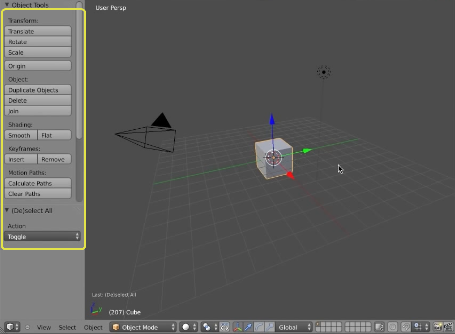 In my case, I use meters as my UOM (unit of measurement) so the value of 0.00010 is equivalent to 0.1mm. If you know what the minimum value is for your 3D printer, then you should set this to the same value, or slightly higher.
Distorted
The individual faces that make up your models should generally be flat, but this is not always the case as moving individual vertices around will affect the faces that they are used to creae.
This is one of those where you do have a slight bit of leeway for distortion but the best way to avoid it entirely is to increase the density of your geometry, as smaller faces are less likely to be heavily distorted.
Be careful not to go too small though as you still want to be able to edit your model without difficulty, The value used to define distortion is set to degrees by default.
It is set to 45 degrees by default, increasing the value increases the threshold for allowing more distortion on your model, while lowering the value makes the tool more sensitive for located distorted geometry.
Thickness
When you are working with a very small object, you need to ensure that there are no parts of the object that lack the thickness necessary to be printed.
For example, you design a character with extended fingers. The design may look good, but if the thickness of the fingers is too small then they will not print correctly.
The minimum thickness is set to 1mm, but many home-based printers go as low as 2mm, so check the specs for your machine and then set the value accordingly.
Sharp Edge
A perfectly sharp edge does not exist in the real world, but it cannot be avoided in 3D modeling. What you can do with your models however is reduce the angles that your edges create to generate a smoother appearance.
Two tools that can be used to reduce that sharp look for your model are the subdivision surface modifier and the bevel modifier.
You can set the value of the sharp edge indicator to any value in degrees to highlight if there are any edges that have an angle equal to or greater than that value.
A basic cube for example has 12 edges and each edge has a value of 90 degrees for its angle. Set the sharp edge value to 90 and select check all, then you will see that the object has 12 sharp edges. Set that same value to 91 and check again, you will find that the number of sharp edges has been reduced to 0.
Higher density objects are less likely to have edges with greater angles, and an ideal value to keep below for printing is 60 degrees. Again you can use bevels to achieve this on your model.
Overhang
When an edge or face is overhanging, then that means it is in a position where it is not directly supported by the rest of the model.
While it is perfectly possible to print with overhangs, there is the risk of structural weakness in these areas of the model. That means that you are most likely to break the model where there are overhangs.
You may not want to change your model though as having overhanging faces may just be a hazard to your chosen design. What you can do instead is set up your printer outside of Blender to create support material, which can be cut off easily after Printing.
Scale To
This tool can be used alongside the volume and area indicators and is very handy if you are working as a business for creating 3D printable models. Say for example you are designing figurines and all of these figurines need to be of a certain size.
Scale To TransformThe ‘scale to’ tool can be used to adjust the volume or area of the model to a specific value. This is a great way to ensure that your products are all the same size or thereabouts.
Clean Up
When you have identified all of your non-manifold geometry, you will be able to use the clean-up tools to get rid of the geometry. Note that this is not a perfect tool and while it will reduce the number of nonmanifold edges on your model it may not eliminate them all depending on the model’s shape.
Clean Up ToolYou should look to combine other tools with the clean up option to make sure that your object is in the best shape possible.
Export
Finally, the addon allows you to export your 3D model as a file format that is suitable for the 3D printing process. You have four options to choose from and each is slightly different but all effective for 3D printing. These formats are:
- OBJ
- PLY
- STL
- 3XD
The obj format is best suited for beginners as it limits the export to simple geometry data, but we tend to use the STL format for objects that we want to prep for 3D printing due to its versatility with the data it stores.
Thanks For Reading The Article
We hope that you were able to find the information that you were looking for. Below we have gathered a list of additional topic articles that we believe you may be interested in.
- How To Organise My Node Setups When Creating Materials?
- Where Does Blender Get All Of Their Money From?
- What Are The Main Features Of The Blender Software?
- How To Identify Normals In Blender?
- Creating A Wireframe Mesh Out Of Any 3D Object
Get 30 Days Free Access To The Blender Course Library
-
How To Convert An Image To Grease Pencil?
Blender offers the ability to create objects of various types, ranging from your typical mesh object to curves, text, etc.
 Since Blender has so many object types, it also offers
Continue Reading
-
How To Design A 3D Model Using An Image?
Most 3D artists will use reference material when designing new objects in 3D modeling applications like Blender. This can be done in different ways, So what is the simplest method
Continue Reading
-
Using The Transform Node In Geometry Nodes?
Geometry nodes are the latest phase of Blender’s incredible development, and it introduces procedural 3D modeling using a node system. For this note system to be successful, it needs to
Continue Reading
How to create 3D printable models in Blender
Blender is an application that provides a set of free and open source 3D computer graphics tools used for the production of animated films, visual effects, art, 3D printed models, motion graphics, interactive 3D applications, virtual reality and computer games.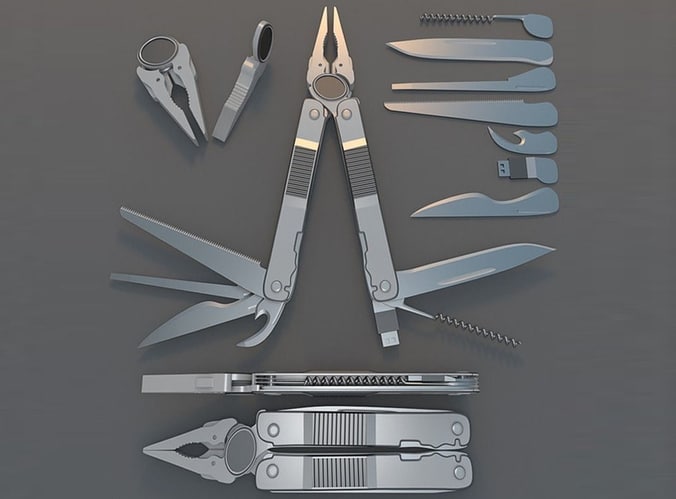 .
.
Blender is a 3D creation kit used by beginners, professionals and enthusiasts for 3D modeling, animation, animation, illustration and more. Although Blender was originally designed for animation, it can still be used to create 3D printable models. If that's what you want to do, follow this guide. Check out the Best Topology Tips and Tricks for Beginners.
1. Enable the 3D Print Toolbox add-in.
Before we start, be sure to install the latest version of Blender, and take a look at the Blender 3.0 Custom Keyboard Shortcuts.
Here are some of the easiest Blender keyboard shortcuts you should know:
- Tab : Press this key if you want to enter edit mode.
- G : allows you to move the headings or form.
- Shift + F : allows you to fill the space between the selected vertices.
- S or C + X or Y or Z : Scale the object along the X, Y or Z axis depending on what you want to do.
To enable the 3D Print Toolbox custom extension, do the following:
- Go to Edit -> Preferences.
- Click tab Supplements .
- Find a 3D printing toolbox.
This is the handy tool we need to prepare your model for a smooth and successful 3D printing process.
2. Prepare your 3D model
You probably already have a 3D model that you might want to use. If not, there are plenty of free templates available from sites like Thingiverse or Cults 3D. However, not all of them are designed for 3D printing. So, you can create your own 3D model in Blender.
If you're new to Blender, be sure to check out our tutorials on How to Group Objects and Merge Objects, as well as easy 3D models for beginners in Blender.
3. 3D Model Optimization
Once you have your template ready, there is one very important thing you need to remember right now. Your model should be one solid filled object. This means there are no missing heads or holes in your model.
In other words, this 3D model must be diverse. For a model to be diverse, it must be surrounded by an area that could exist in real life. This means street geometry can be 3D printed.
So, depending on your model, some finishing touches may be needed. This process is quite simple, keep following.
If your object is complex, chances are it won't be fully complex. Let's check it out; Follow these steps:
- Select the object you want to check.
- press the key. N to show the toolbar.
- select section 3D Printing Tool Kit .
- Click the Check All button.
- Look at the results and make sure the unvarnished edge shows 0.
If so, your template is ready to be exported as an STL file to a slicing application. But it can show a number greater than 0. Read on to solve this problem...
Unbranched Mold Repair: Method XNUMX
Let's start with the simplest way to repair an unbranched model. We can use Blender's built-in cleanup tool. You can find it next to the button. check all As described in the previous section. There you will find the cleaning section. Do the following:
- Select your model.
- Open the cleanup section.
- Find Make manifold .
This should also work in older versions of Blender. This approach has a small drawback: it can mess up your 3D model. If so, is there another way...
Unbranched Shape Repair: Method XNUMX
Instead of using Blender, you can use an external application called . 3D Builder from Microsoft. It is available on Windows 11 and 10. After downloading and installing 3D Builder, open the app and import your model. Then do the following:
- Go to Open -> Open object .
- Navigate to your 3D model wherever it is saved on your computer.
- Press import model .
3D Builder will let you know if there are errors or not, with pop-up notifications suggesting how to fix them. After completing the necessary steps, the 3D model should be branched.
As a note, when using the 3D Builder, the shape of the model can be changed to make it branched. However, it is still cleaner and these changes are natural to make it more printable.
4. Import your model into the slicing application
The last step is to export the model from Blender and import it into the Slicing application. The Slicing app is an app that converts a model into instructions for printing on a 3D printer; This set of instructions is called Gcode. In particular, it contains G and M commands, each of which performs a specific action.
In other words, this is the language used to tell the machine how to move parts or what pattern to follow to create an impression. These instructions may also contain user-selectable options such as print speed and support structure; All this can be done in a special application for slicing.
Before we can import the model into the slicing application, we need to export it as an STL file. STL stands for Standard Mosaic Language or Standard Triangle Language and describes the surface geometry of a 3D object. It cannot be printed by itself. So let's go ahead and export the object as an STL file by going to File -> Export -> Stl (.stl) in Blender.
Then import it into a slicing application such as Care. In Cura, you can simply drag and drop a form into it and the form will look like the image above.
Once you have your model in the slicing app, you can start 3D printing it. Be sure to check out our guide to Cura plugins that will make 3D printing more reliable and convenient.
Creating 3D Models for Printing in Blender
In this article, we looked at how to prepare a 3D model for printing in Blender. We also showed you several ways to create another 3D model and then import it into a custom slicing application. Please refer to this guide if you would like to create a 3D printable model. You can now check out the Best CAD Apps for Kids to get started with XNUMXD designs.
Source
Blender 3D for 3D printers
Correct position! But some problems can still be covered by polygonal modeling.
Gathered here the answers to the four most common and non-obvious problems.
Dimensions
When I tried to order 3D printing from a company for the first time about seven years ago, it was like this:
— Igor! You sent an empty file!
- No! Here's a screenshot, well!
One meter in Blender is equal to one millimeter in Slicer, nothing has changed in these seven years.
Designing in meters is wonderfully inconvenient, so when exporting to STL/OBJ, set the Scale value to 1000:
Closed geometry The ability to create open geometry is both a scourge and a bonus of polygonal modeling.
In the modern world, slicers (not all) have learned to work with this, but there may be surprises: want a hole? get a blank wall!
If you don't like surprises, you should use Blender's geometry analyzer.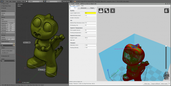
In the mesh edit mode, select the vertex selection, and click Select → Select All By Trail → Non Manifold
To eliminate such trash as on the right ball, there is a Merge By Distance tool. Lives in Mesh → Clean Up → Merge By Distance.
In other cases, it is necessary either to give the wall thickness by extruding, or to close up the hole, or is this geometry really necessary?
And now for the good news: in Blender 2.8 the 3D printing addon is built right into Blender, hooray! Geometry analysis just got easier. You just need to turn it on, and in the edit mode in the N-panel everything will be (and even the preliminary volume of the model!).
Flying geometry
As unclosed, only flying. So the slicer can still try to shove it into the G-code!
The annoyance is that if the volume of the walls was made by a modifier, these mesh pieces can no longer be found with the Non Manifold tool.
Select any polygon on the target mesh, and use the Ctrl+L hotkey: it will add all physically connected polygons to the selection. After that, invert the selection with the Ctrl+I hotkey and delete everything you don't need.
Normals
Roughly speaking, the polygon has a "face". When the polygon enters the slicer, the slicer looks at where the polygon has a “face”, tries to fill the wrong side with plastic, and at the same time checks for overhangs.
Accordingly, a cube with normals inside will be perceived clumsily. In fairness, in modern slicers this is no longer so important.
The solution is super-simple: turn on the display of normals:
Flip in the right direction: select the polygon with the normal turned inside out and press Alt+N. Hoba! and the slicer no longer panics about negative angles where they cannot exist.
Generalize
Blender, indeed, is not developed as engineering software, and you should not try to solve furious tasks with it in the spirit of multicomponent kinematic systems.


