Atmega2560 3d printer
RAMPS 1.6 3D PRINTER CONTROLLER + Mega 2560 Atmega16u2/Atmega2560 + 5x A4988 2A Drivers
$21.95
(No reviews yet) Write a Review
RAMPS 1.6 3D PRINTER CONTROLLER + Mega 2560 Atmega16u2/Atmega2560 + 5x A4988 2A Drivers
Rating Required Select Rating1 star (worst)2 stars3 stars (average)4 stars5 stars (best)
Name
Email Required
Review Subject Required
Comments Required
- SKU:
- KT-RMP1.
6-MEGA-A4988
- Price:
- $21.95
- Availability:
- In Stock
- Order Now:
Current Stock:
Quantity:
- Description
This complete Ramps 1.6 3D printer controller kit includes following items:
- 1x Mega 2560 R3 Atmega16u2 and Atmega2560 Arduino Board - No driver needed for Windows 7 and later OS (Please note this is a clone version of the original Arduino Mega 2560 with Atmega16u2 and Atmega2560 chips. It is licensed under Arduino's Creative Commons Attribution Share-Alike license.
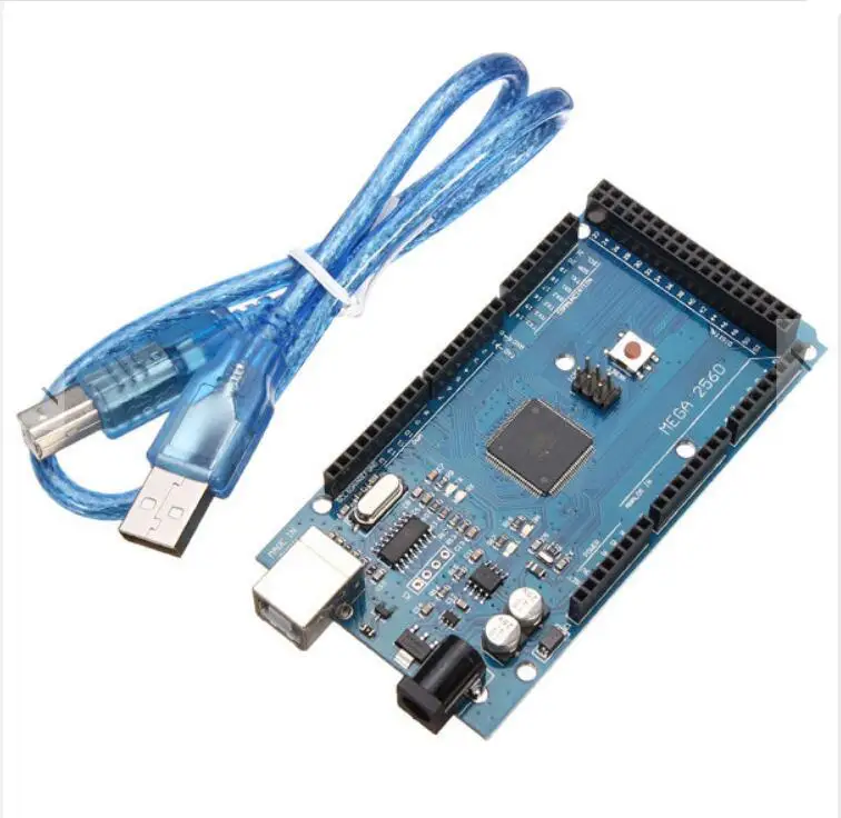 The Arduino logo is protected by copyright - be aware of boards that have the Arduino logo, as they are often mis-represented as "genuine" Arduino boards.)
 - 1x Ramps 1.6 board w/ jumpers and power connector
- 5x A4988 2A (maximum 2A/phase, w/sufficient cooling) stepper driver
- 5x Aluminum heat sink w/ 3M tape backing
- 1X 20" high quality USB cable
New ZYLtech RAMPS 1.6 3D Printer Shield for Arduino
Features:
- Larger bed MOSFET
- Screw terminal power connection is safer and more reliable
- Larger heat sink for more efficient heat dissipation
- Surface-mounted fuses and flush MOSFETS
Specs:
- 101.5mm x 60.5 (67.5 including reset button protrusion) x 30mm thickness overall
- 4 layer PCB
- Input Voltage - 12V
- Power - 200W
- Driver Support - A4988, DRV8825, TMC2130, TMC2208 (up to 5 stepper motors supported)
If you need a 1.4 board they are also available here:
- Related Products
- Customers Also Viewed
RAMPS 2560 Electronics - Atmega 2560 (Arduino-compatible) | 3D printing experts
Overview Description Documentation Specifications Related products
Stock - NL: 9
€ 22.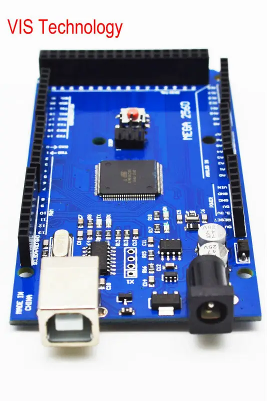 27 excl VAT In stock
Only 9 left, order now!
Product description
Versatile development board with the famous Atmega2560 chip. You can upload your own program to the board using Arduino software.
The RAMPS 2560 Electronics is a microcontroller board based on the ATmega2560. It has 54 digital input/output pins (of which 14 can be used as PWM outputs), 16 analog inputs, 4 UARTs (hardware serial ports), a 16 MHz crystal oscillator, a USB connection, a power jack, an ICSP header, and a reset button. It contains everything needed to support the microcontroller; simply connect it to a computer with a USB cable or power it with a AC-to-DC adapter or battery to get started. The Mega is compatible with most shields designed for the Arduino, Mega Duemilanove or Diecimila.
This is a clone board with the Ch440G USB-to-Serial chip.
Documentation
Driver
Specifications
| sku | MEGA2560 |
|---|---|
| gtin | 8719128322544 |
| Processor | |
| Technology | AVR |
| Type | ATmega2560 |
| Frequency | 16 MHz |
| Memory | 256 |
| Dimensions | |
| Length | 110 mm |
| Depth | 54 mm |
| Height | 14 mm |
Price breaks
| 1 - 9: | excl € 22.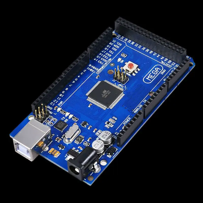 27 27 |
| 10 - 29: | excl € 21.16 |
| 30 - : | excl € 20.05 |
| Need a larger quantity? Contact our Sales department. | |
Related products
Discover products that go hand in hand with the RAMPS 2560 Electronics - Atmega 2560 (Arduino-compatible). These are products that have been purchased the most with the RAMPS 2560 Electronics - Atmega 2560 (Arduino-compatible). Do not miss out on items that will cut down on time, boost efficiency, and provide the best experience.
RAMPS v1.4 - Pre-assembled 3D printer board
€ 13.26
DRV8825 Stepstick 1/32 microstep Stepper Motor Driver
Pololu-compatible 2A 1/32 microsteps modular stepper driver
€ 5.74
LCD - 20X4 - blue/white
Character display LCD
€ 18.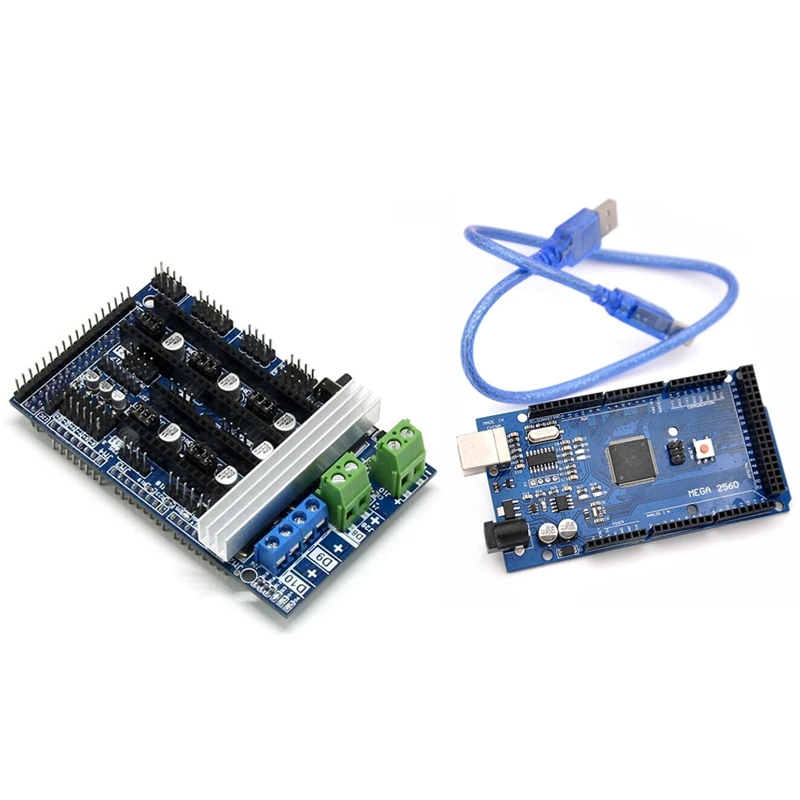 55
55
ReprapWorld
Graphical LCD screen v1.0
Cool 128x64 full graphical LCD (SPI)
€ 38.80
We bring to mind the Arduino Mega 2560 + RAMPS1.4
Hello comrades.
Topics with jambs RAMPS pop up all the time. There are many solutions to these jambs, but everything is scattered across the comments and forums. In the process of collecting and applying this information, it was killed: Arduin 1 pc, Ramps 1 pc, about a dozen transistors. The result of my torment was that for half a year I had not looked into the electronics compartment due to the failure of something.
As you already understood, we will talk about a common set of Arduino Mega 2560 + Ramps 1.4. Probably the most common and, for sure, the most affordable electronics kit for a 3D printer.
[IMG ID=32274 WIDTH=199 HEIGHT=199][IMG ID=32275 WIDTH=193 HEIGHT=193]
In this post, I will describe step by step what I did with a description of how to do it.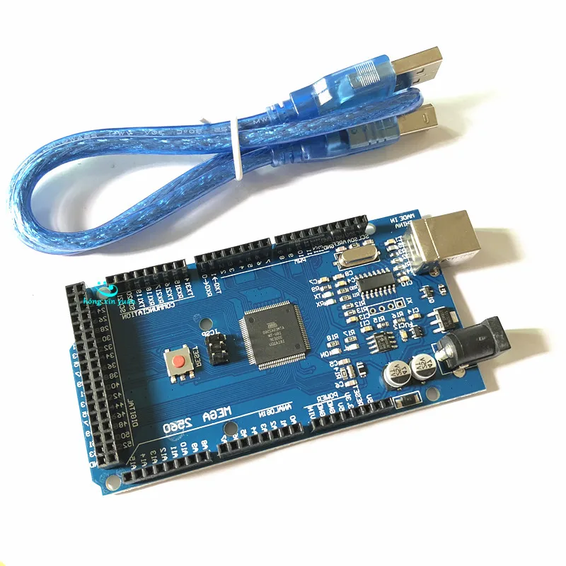 Whether to follow these points (all or some) is up to you. Also, I am not responsible if you burn something there. I also warn you that I am not an electronics engineer, everything described here was not invented by me. I just want to put together the most, in my opinion, successful and necessary alterations.
So let's start.
1. The first thing I recommend to do is to throw out the green connector from the RAMPS. If you follow further advice, it will not be needed. But even if not, just throw it away and solder wires in its place. This connector is too weak for the current required to power the table. Over time, it will melt, which will lead to sad consequences.
If you remake the power supply of the table according to the instructions in point 3, then you need to solder only two wires instead of the green connector. On the board under the connector, the power contacts are numbered. Contact number 4 is a minus. Number 3 is a plus. We solder the wires to them and connect them to the power supply.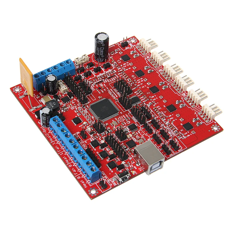
2. Remove diode D1 from RAMPS. This will separate the power of the RAMPS, and accordingly the motors, drivers and everything else, from the power of the Arduino. Why this is necessary will be clear from the following paragraphs.
[IMG ID=32276 WIDTH=393 HEIGHT=230]
3. Now, probably, the most important and necessary item. Questions about it pop up at least once a month. Organization of normal meals of the table.
What you need:
- First of all, you need a normal power transistor. Those that the Chinese put are not suitable, although they work. Suitable transistor models: IRL 3705n, IRL2203n, IRL3803, IRL2505. Choose what is the cheapest in your radio products (the price is usually from 30 to 100 rubles), if there is none of this, look for analogues in Google, there are a lot of them. The parameters should be as follows: drain current from 30A, the higher the better, source-drain voltage from 25V, gate voltage 4.5V, TO220AB package. I understand that seasoned electronic engineers will attack me with shouts, that these are far from all the important parameters, but I selected them according to them and everything works for me, so why should I climb into the jungle?
- Wires.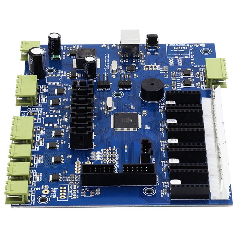 I use Chinese 14AWG wires. They are enough and they do not heat up. Look for a plate of correspondence with our sections in Google.
- Soldering iron from 60 watts. RAMPS is quite difficult to solder, or rather to solder out of it. So practice on the old mainland.
- Aluminum radiator. Sizes from 20x20x20mm and above. You can do without it, more on that below.
- Any small items for soldering, solder, flux, heat shrink, etc. If you don't know what it is, don't take it.
Now directly to the process:
The first thing to do is to unsolder the table's native power transistor.
[IMG ID=32278 WIDTH=307 HEIGHT=307]
We won't need it anymore. You can, of course, use it, but it will get very hot even on a radiator, so it's easier to buy a normal transistor for 50r.
Now, instead of the leg, which is located closer to the large orange fuses, you need to solder either the wires (you can use any thin wire) or, as I did, a pin like those located along the edges of the RAMPS.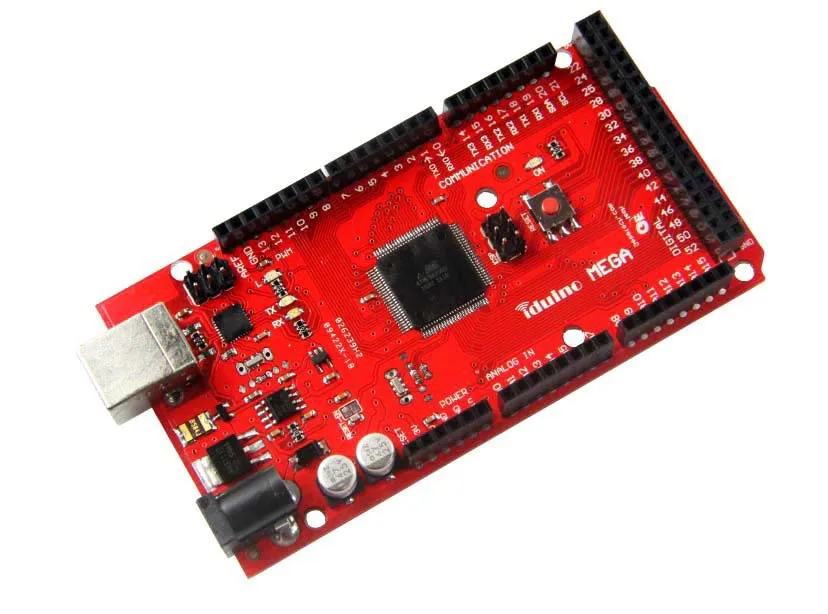 You can take it from any old motherboard (yes, there are many where they are used). I soldered the pin so that I could turn it off at any time without worrying about soldering RAMPS.
We are done with RAMPS for now. Let's start with the transistor.
Everything is connected quite simply.
- From the left leg (shutter) the wire connects to the RAMPS, to the same pin. The connector for such contacts is sold under the name BLS-01.
- The central leg (drain) is connected to one of the contacts of the table (polarity is not important for the table).
- The right leg (source) is connected directly to the MINUS power supply.
All wires are carefully soldered and insulated with heat shrink.
From the second contact of the table, the wire is connected directly to the PLUS power supply. I pay close attention to the polarity of the connection. The table does not care where you connect the plus and minus, but the transistor does not.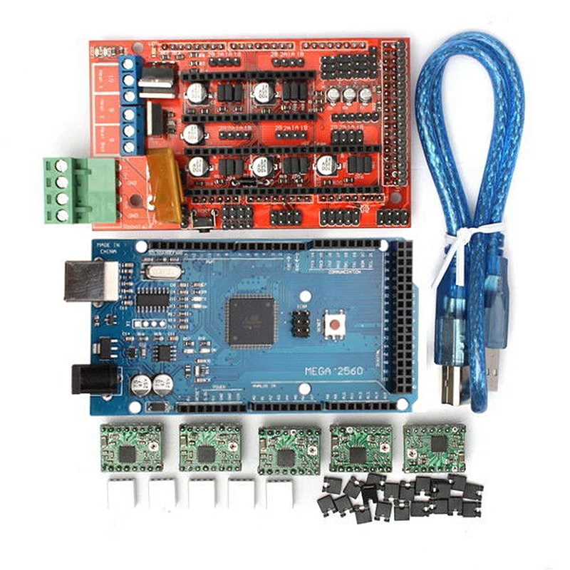 The transistor should hang on the negative line.
Now it remains to screw or glue the transistor to the heatsink. I made it easier, screwed the transistor through thermal paste directly to the power supply case into the standard hole. Fortunately, the PSU case is aluminum. Now the transistor is always cold.
As a result of this alteration, we started the table power bypassing the RAMPS. From RAMPS only a signal goes to the gate of the transistor. The power for the rest of the electronics (except for Arduino) still goes through the RAMPs along the wires that we soldered in step 1. Please note that the negative wire from the RAMPS and the wire from the right leg (source) of the transistor must be connected to the same negative contact of the block nutrition.
4. Now let's talk about the Arduino power supply. In paragraph 2, I recommended to separate the power supply of Arduino and RAMPS. There are two reasons for this.
Firstly, 12 volts for the Arduino converter is a lot, this is its limit value and at this voltage it does not heat up slightly and can burn out.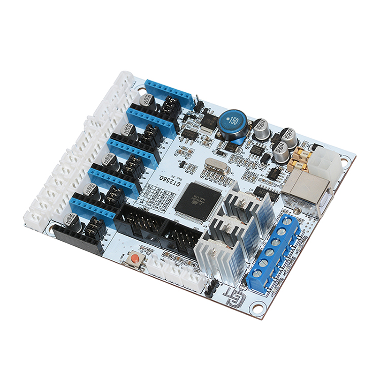 Especially if you connect additional consumers, such as a display.
Secondly, this will raise the supply voltage of the RAMPS above 12 Volts.
Why raise the RAMPS supply voltage. There is only one reason - to speed up the heating of the table. At 12V, the table heats up for a long time. The time depends on the specific instance, or rather on its resistance. It can take up to 15 minutes, which is a very long time. There is, of course, an option with altering the table to a lower resistance, but, in my opinion, it is easier to tweak the voltage on the PSU. I set my PSU to 15V. At the same time, I have a standard 12V heater on the hot end and the table is connected according to the 12V circuit. The table heats up to 100 degrees in 4-5 minutes without any insulation. The only thing I had to do was to run a PID test on the M303 command to even out the temperature of the hot end. Despite the increased supply voltage of the hotend heater, the temperature is kept within +-0.5 degrees from the set one.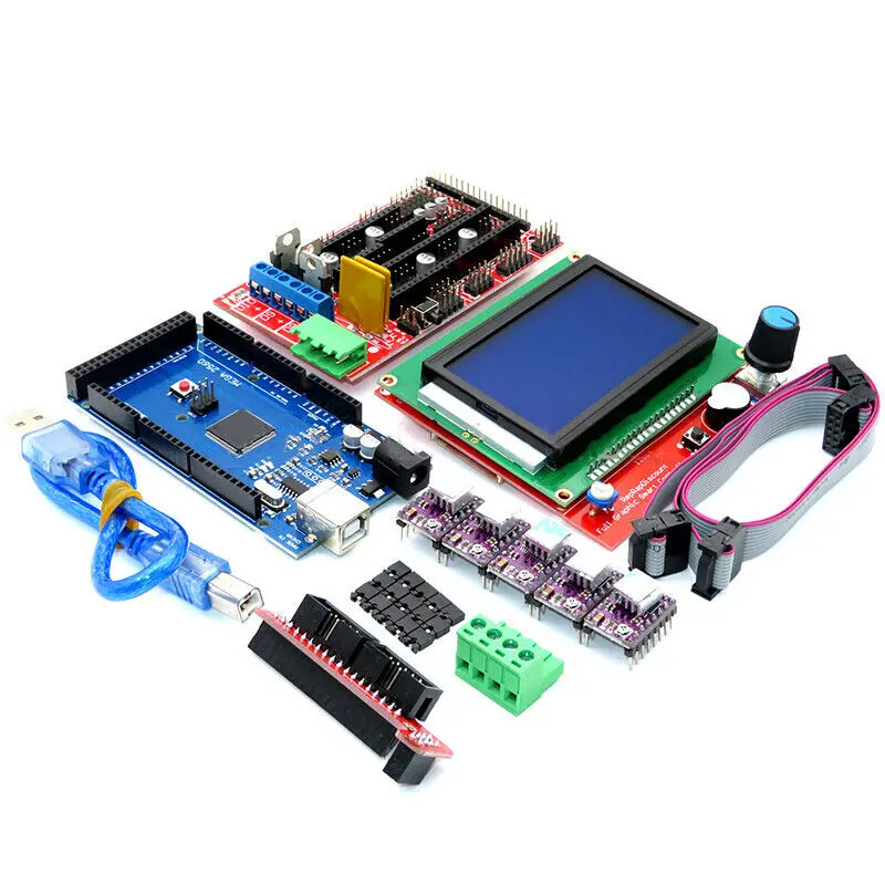
How to power the Arduino? There are two options.
First, power it from USB. The most simple and inconvenient. I've been using the printer this way for quite some time. If you print from a computer, do not connect additional equipment to the Arduino (server, display), then it is quite a working option. About the disadvantages of such a connection, I think, it’s not worth talking about.
Second option, DC-DC buck converter. Here's one.
[IMG ID=32280 WIDTH=226 HEIGHT=226]
Worth a penny. Connecting is very simple. The IN pins are powered by the PSU, the OUT pins are powered by the round Arduino connector. First you need to set the voltage output by the converter to 7-9 Volts. This is the optimal voltage for the Arduino native converter. For greater reliability and space saving, I removed the round connector from the Arduino and soldered the wires from the converter directly to the board. Now, when you connect a display with a card reader, the printer becomes autonomous from the computer.
5. Last point. Cooling fans for hot end and electronics. Usually the fans are connected to the RAMPS, but due to the fact that we raised the voltage, the fans began to work with overload. Not only does this reduce their lifespan, they also get loud as hell. The solution is simple. Another converter from point 4 connected to the PSU. This connection also allows you to adjust the fan speed and choose it so that it would not be too loud and enough for cooling.
But this is a temporary solution, because Recently I saw here an article about just such a module. Ordered, I will connect the fans through it.
That's it. I hope the article will be useful.
Uno, Mega 2560, CNC Shield v3.0
The3D printer has found application in many areas. It is used both in industry and at home. But sometimes it’s not affordable to buy ready-made equipment, so those who want to get it have to decide to make a 3D printer on their own.
In this regard, there was a need for kits for the Arduino 3d printer.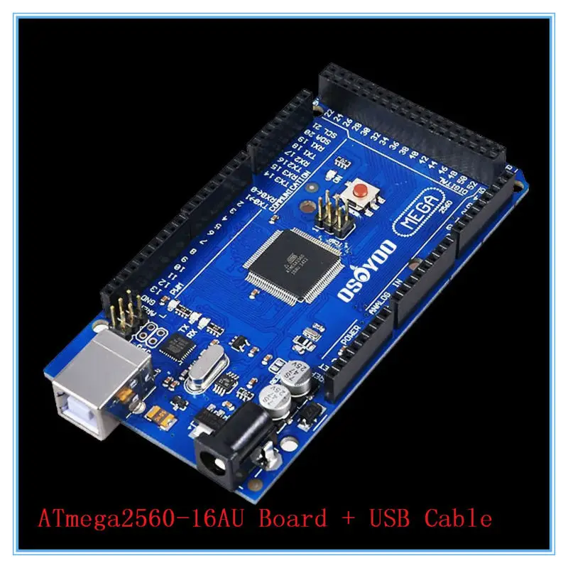 Their popularity is due to low prices for electronics and an acceptable level of performance of the assembled processor. Arduino is a brand of hardware and software tools for making automated robotic systems. The products of this brand are intended for non-professionals.
3D printer
The standard set consists of IDE (software shell) and hardware. The latter is a complex of mounted printed circuit boards, and they can be sold by both a third-party and an official manufacturer. They note the openness of the system architecture, which predetermines the constant addition and problem-free copying of the developed products.
Such a device makes the boards the universal core of the system in which they are included. IDE is a programming language designed specifically for Arduino.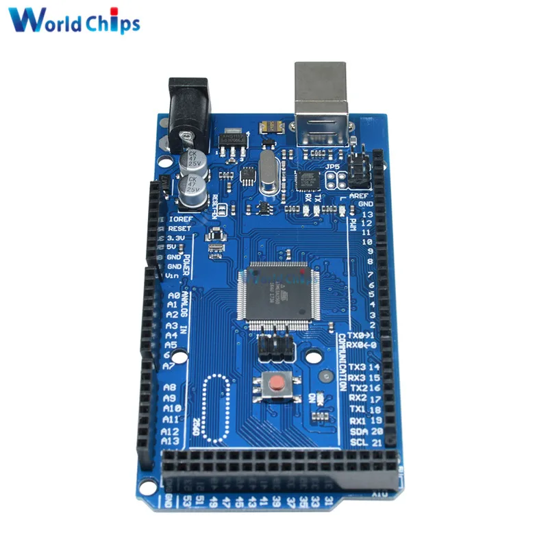
How to build an Arduino 3D printer with your own hands
It is quite possible to make a 3D printer with your own hands, for this you need to follow the instructions that came with the Arduino kit. You can also be guided by the recommendations of professionals and methodological manuals.
Arduino board design
3D printer consists of the following parts:
- case;
- controllers;
- guides;
- power supply;
- stepper motors;
- extruder.
The first step is to build the coordinate axes. To do this, you need drives, for example, from CD / DVD, which were on the computer. You also need to purchase a floppy drive, checking its performance is required. Its indicator is the step-by-step mode of operation, which is carried out without direct current. Next you need to choose stepper motors. The process of moving consumables requires a certain amount of power.
Arduino 3D printer
The next step is to choose the electronics.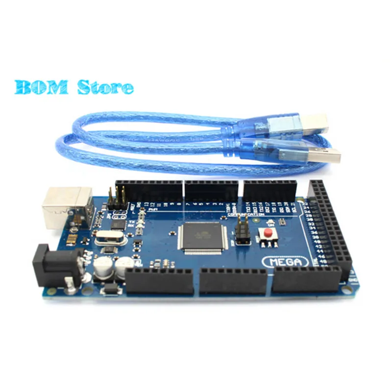 You will need the Arduino board itself, a cable, drivers (5 pieces), radiators, a power supply (suitable from a computer), a fan, limit switches (optical or magnetic), a heating table, a thermistor, a transistor, wires, plugs, a heating device for a hot end, nozzles and bowden. You can really buy them in a set, this will save time and effort without damaging the quality. You can find the assembly diagram of the parts on the Internet.
At the last stage, download the Arduino IDE, install the firmware (Marlin is more often used) and connect to the CNC controller. Having checked the assembly of electronics in this way, you need to decide on the software that will be responsible for controlling the 3D printer. An example in the photo.
Its functions include the acceptability of selected print parameters: infill, section height, and consumable layering speed. It remains only to assess the condition of the electrical wiring, assemble the last elements (frame, case, fasteners) in accordance with the instructions and connect the printer assembled by oneself to a PC.
The 3D printer is calibrated according to the pulley diameter, the number of steps per motor revolution and the micro-steps in the electronics system. The result of the operation is the final configuration of the firmware.
Arduino UNO board
The Arduino UNO board works with the ATmega328 microcontroller, which is characterized by:
- 14 digital and 6 analog ports;
- USB ports;
- reset functions;
- in-circuit programming and power connectors.
The expansion board provides power to the above components, for example via USB. The location of the microcontroller facilitates its replacement and repair.
Arduino UNO has several differences from other modifications of the expansion boards of this company:
- First, it does not need a USB-UART FTDI bridge to connect it to a PC.

- Secondly, it receives electricity through the USB port and with the help of devices from the outside. Several pins are predefined for this (Vin, IOREF, 5 V, GND).
- Third, the Arduino UNO microcontroller has three types of memory: FLASH, EEPROM, and SRAM.
- Fourth, there is a sequence in SPI. This applies from 10 to 13 exit (input).
- Fifth, there is an automatic reset function.
- Sixth, there is protection against the effects of wire heating.
Arduino UNO
Arduino Uno 3D printer is considered the most popular in its price category.
Arduino Mega 2560 for 3D printer
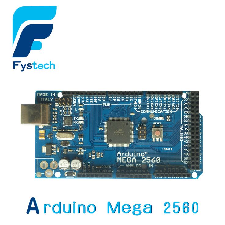
It is based on the Arduino Mega. The Arduino Mega 2560 required an improved ATmega2560. The device has:
- 54 digital and 16 analog inputs;
- UART, USB;
- resonator;
- ISCP;
- reset function.
Mega 2560 board
Arduino Mega 2560 connections are made by connecting to a PC or to an external power source.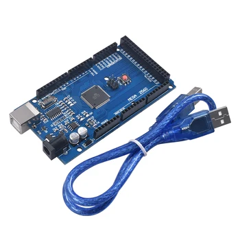 The main differences of the innovation:
- No need for USB-to-serial.
- Resistor present.
- Adding SCL and SDA pins to the Arduino Mega 2560.
- Strengthening the RESET work sequence.
The Arduino Mega 2560 3d printer is a popular 3d printer available. This is due to the performance of his work.
Arduino CNC Shield v3.02
CNC Shield v3.02 expansion board designed for Arduino UNO 3D printers and similar equipment. This I/O base allows devices to operate in automatic mode or by connecting to a USB port.
Arduino CNC Shield v3.02
Arduino CNC Shield v3.02 has 4 axes, two kinds of interface (UART, I2C). The required voltage for the power and logic parts is 36 V and 5 V, respectively. The firmware type of this board is called Arduino GRBL. The base is characterized by four slots (according to the number of axes) and jumpers for their duplication. Arduino CNC Shield v3.02 drivers are connected in different ways.