Hdi 3d scanner
HDI Advance 3D Scanner - Innovia3D
Flexible 3D Scanning System
Versatile in Use Across Applications
While commercial 3D scanning systems have typically been expensive and limited to specific objects they can scan, the HDI Advance is an affordable 3D scanning system that is versatile across many applications. The system uses structured-light technology to take measurements of a physical object in 3D space and delivers stunning high-resolution digital 3D scans with accuracy. Multiple scans are stitched together to create a complete 3D representation of the part.
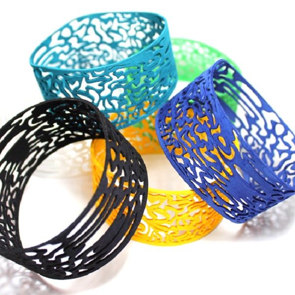
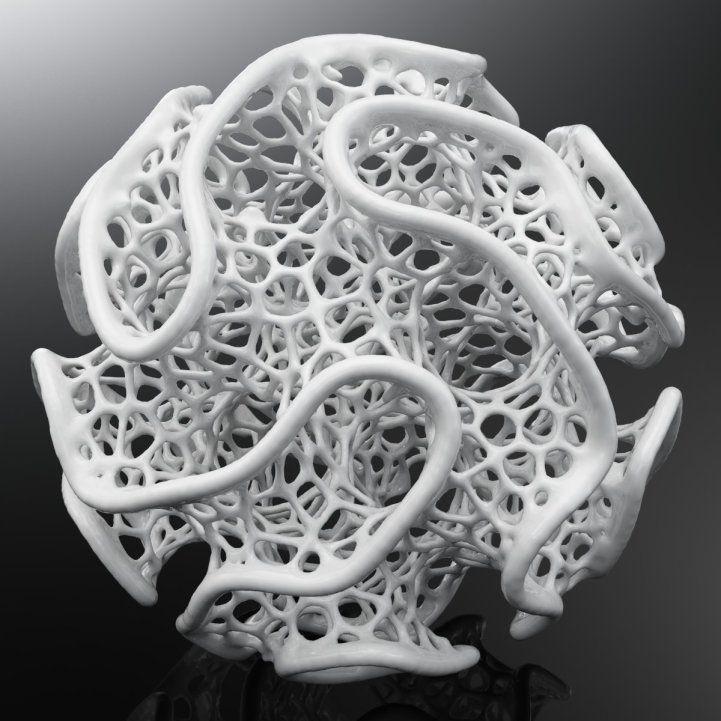
Great for Scanning Objects with Organic Shapes
Scans even complex parts with freeform surfaces that is difficult for digitizers such as contact probe to scan.
Fast Scan Speed with Full Field Scanning in 1 Second
Captures the full field of the object in just one scan for faster scanning time. A single scan is produced in about 1 second.
Built-in Post Processing for Scan Data Cleanup
Acquires 3D scans and processes the scan data (align, merge, and cleanup) for a seamless 3D scanning experience.
Seamless 3D Scanning Experience
From 3D Scanning to Post-Processing
3D Scanner Model Comparison
Select the model most suitable for your projects.
HDI Advance R1x
Resolution
1.1 million points/scan
(2.2 million polygons)
Accuracy
Up to 60 microns/scan
Scan Speed
1.3 seconds
HDI Advance R3x
Resolution
2.6 million points/scan
(5.2 million polygons)
Accuracy
Up to 40 microns/scan
Scan Speed
1.2 seconds
HDI Advance R5x
Resolution
4.9 million points/scan
(10.1 million polygons)
Accuracy
Up to 25 microns/scan
Scan Speed
1.2 seconds
Download Brochure
Pushing the Boundaries of 3D Scanning Technology
Flexibility for users to easily adapt the system to fit their needs.
Technical Support Packages
Additional help is available
The purchase of HDI Advance 3D Scanner includes updates to FlexScan3D software for one year.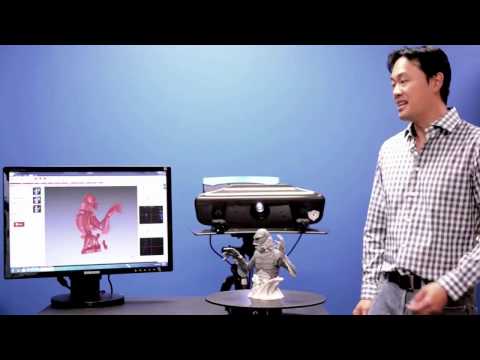 Additional support packages are also available for further assistance:
One Year Priority Technical Support
- Email support: Priority email response rate is answered within 24 business hours of receiving the correspondence.
- One phone call with remote computer access: Our technical specialist logs into your computer using remote access technology to help you with setting up the 3D scanner or scanning an object.
- Two phone support calls up to 45 minutes each.
On-Site Training
We offer one-on-one assistance to help you get started on 3D scanning. Training can take place either at Innovia3D’s head office in Elmhurst, Illinois or at your facility.
Request a Quote
Request HDI Advance pricing information.
Contact UsHDI Advance Professional 3D Scanner
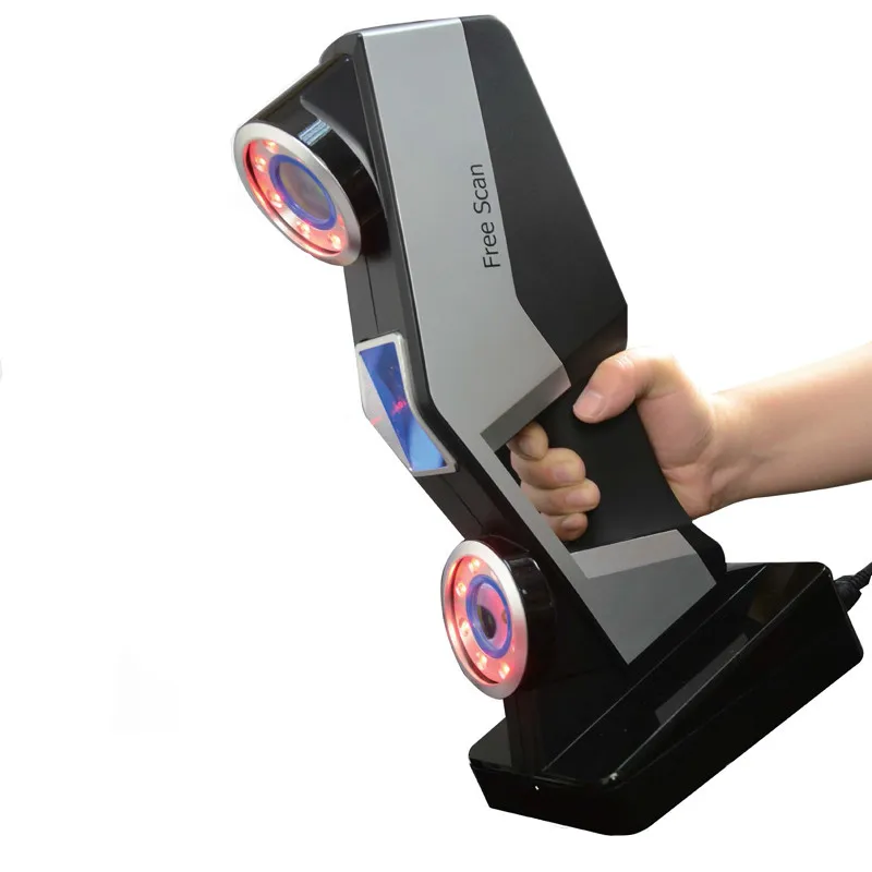
the flexible 3D scanner
HDI Advance’s flexible configuration makes it a versatile system for 3D scanning parts large to small.
Key Features
HDI Advance
A 3D scanner that gives you control to adjust the scanning volume, whenever you need it. Do all your scanning using one system.
-
Your Go-To 3D Scanner
While other 3D scanning systems may be limited to scanning only similar sized objects, the HDI Advance has the flexibility to scan a wide range of parts, objects, and people into full digital 3D models.
-
Adjustable Field of View
While other 3D scanning systems may be limited to scanning only similar sized objects, the HDI Advance has the flexibility to change the observable area (field of view). Make the field of view smaller or bigger by placing the cameras in different preset slots on the mount.
Additional Features
-
Capture High Quality 3D Scans
Each scanner uses a pair of machine vision cameras for capturing high resolution and accurate 3D scans.
 The HDI Advance 3D scanners deliver industrial grade quality and geometry, great for professional applications including reverse engineering and 3D inspection.
 -
Capture Objects in Colour
The HDI Advance is available as a colour option for projects where you need to capture objects in true colour likeness.
-
Upgrade 3D Scanning Performance
There’s no need to buy a new system if your scanning needs evolve over time. The HDI Advance 3D scanner is a component-based system, meaning that you can upgrade the scanner’s hardware components easily. Switch out the cameras/lenses for better accuracy and resolution.
Technical Specifications
HDI Advance R1x
Scan Speed
1.3 second per scan
Accuracy
165mm FOV: 60µm (0.0024″)
310mm FOV: 105µm (0.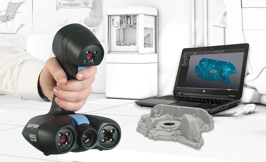 0041″)
455mm FOV: 115µm (0.0045″)
Average Points
1.1 million per scan
Average Polygons
2.2 million per scan
HDI Advance R3x
Scan Speed
1.2 second per scan
Accuracy
200mm FOV: 40µm (0.0016″)
400mm FOV: 65µm (0.0026″)
600mm FOV: 85µm (0.0033″)
Average Points
2.6 million per scan
Average Polygons
5.2 million per scan
HDI Advance R5x
Scan Speed
1.2 second per scan
Accuracy
200mm FOV: 25µm (0.0010″)
400mm FOV: 35µm (0.0014″)
600mm FOV: 50µm (0.0020″)
Average Points
4.9 million per scan
Average Polygons
10.1 million per scan
Download Brochure »
3D Scan Samples
- Motorbike
- Plastic bottle
- Pulley
- Car bumper
If you would like a quote on the system or simply have questions about how the HDI Advance 3D scanners work, please feel free to get in touch with us.
Contact Us »
Overview and testing of the 3D scanner HP 3D Structured Light Scanner Pro S3 / Sudo Null IT News
Greetings.
Recently, at work, I had a chance to test a 3D scanner from Hewlett Packard - HP 3D Structured Light Scanner Pro S3. Therefore, I decided to share with you my experience of using it. This scanner uses SLS structured light technology. The essence of the technology is that various template images are projected onto the scanned object using a conventional LED-DLP projector. A camera installed nearby captures the resulting distorted images. After that, a special program for these distortions evaluates the shape, depth, details of the object and recalculates all this data into a three-dimensional image.
By and large, this scanner is not new and is a DAVID SLS-3 3D scanner.
Hewlett Packard bought DAVID with all their developments and now produces this scanner under its own brand. The device itself has not undergone almost any changes. The software has changed appearance, but all the main functionality remains the same.
The scanner consists of several components. The projector, oddly enough, is an Acer K132 with a resolution of 1280x800 and a brightness of 500 lumens. Camera – HP 3D HD Camera Pro 2.3MP. The camera and projector are mounted on a special slider rail. And the camera, in turn, is also fixed to a special swivel mount. A ruler is marked on the slider and there are holes for fixing the projector in different places. The degrees of rotation are marked on the swivel mount of the camera. The whole structure is mounted on a Hahnel triad 40 lite tripod.
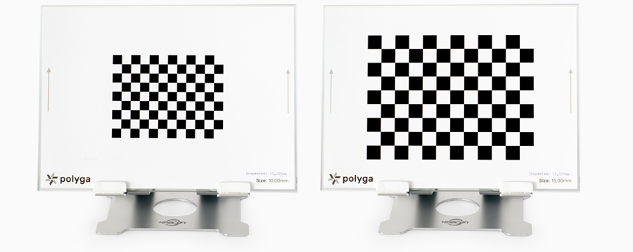
Also included in the kit are all the necessary wires for connection and a USB key-flash drive, it also contains the software. For calibration, two glass panels are used, with markers of different sizes applied to them on both sides. The panels are interconnected by flexible fasteners and are installed on special plastic corners. Additionally, for this scanner, you can buy another camera, there is also a turntable. But this instance is with one chamber and without a table.
The manufacturer promises scanning accuracy up to 50 microns (0.05% of the total object size), while the size of the model can be from 6 to 50 centimeters.
Let's move on to preparing the scanner for work. Out of the box, the camera and lens are already mounted on the rail. You just need to install all this on a tripod using a special mount. The camera is initially installed to the left of the projector. This option is suitable for scanning objects up to 350mm. In case you need to scan an object larger than 350mm, the camera must be installed to the right of the projector. To do this, unscrew the lamb of the projector mount and rotate it 180 degrees. After that, unscrew the restrictive bolt from the edge of the guide, unscrew the lamb of the camera mount, remove the camera from the guide, also turn it 180 degrees and fix everything back. The distance from the camera to the projector and the angle of its rotation depends on the size and type of the object being scanned, we will adjust them before calibration.
Next, you need to connect the projector to the power supply and to the computer using an HDMI cable. The camera is connected to a computer with a USB 3.0 cable and is powered by it. We turn on the projector, in the operating system you need to configure it as a second monitor. After that, you need to install the software. You can do this from the USB flash drive that comes with the kit, or download from the HP website. With a full installation, all the necessary drivers will be installed automatically. The projector should display a table with horizontal and vertical lines.
And so, we launch the installed HP 3D Scan program. The recommended system requirements for it are not very high: a dual-core 2GHz processor, 8GB of RAM and an Nvidia or AMD video card. But, of course, the more powerful the computer, the faster the processing will be.
In the first tab, Settings, you need to select the type of scanner, in our case it is HP 3D Structured Light Scanner Pro S3. Projector - Acer K132. And turn on the camera, we have it HP 3D 2.3MP Cam PRO. On the right there is an exposure setting (or rather shutter speed), as a rule, it should be set to 1/60 so that there is no flicker. And the brightness, it is better to always keep it at the maximum.
It is desirable to choose objects for scanning without transparent or reflective surfaces. It is also not desirable that the object be very dark or black. Black absorbs light, making the projected image very hard to see on the camera. If the object does not meet these conditions, it is necessary to cover it with a special matting spray. The background when scanning is vice versa, it is better to use black, then there will be no need to remove it. If this is not possible, the program can automatically remove the background, but more on that later.
For the first test, I chose a rather difficult object to scan, such an elephant. It has a difficult terrain in some places, protruding elements, and besides, it is quite dark, which makes scanning even more difficult.
The projector and camera need to be set up. We expose the projector in such a way that the image falls on the entire object and is slightly larger than it. Keep in mind that during the scanning process, the object will need to be rotated, and it is desirable that it be highlighted in any position. Now you need to focus the projector, this is done using the adjustment lever on the top of the projector. The point of intersection of the center lines of the projected image must be clearly focused on the object being scanned.
Go to the camera. The angle of rotation is used from 20 to 30 degrees. As a rule, the optimal angle is considered to be 22 degrees. When scanning large objects or objects with deep holes, it may be necessary to decrease the angle, but distortion and noise may occur with an angle of less than 20 degrees. For flat objects, it is better to use an angle greater than 22 degrees, up to 30. In our case, the standard 22 degrees is fine. Now you need to set the camera relative to the projector. We loosen the lamb of its fastening and move it along the guide so that the projected image and the scanned object get into the lens.
There are two adjustment rings on the camera lens. Closer to the edge is the focus ring, followed by aperture. Both rings have fixing bolts. The aperture should be set in such a way that the scanned object is neither overexposed nor too dark. So that the projected image can be seen on it.
The focus should be such that the intersection of the center lines is clear. For convenience, you can zoom in on the image in the program using the mouse wheel. The fixing bolts must be tightened so that the settings do not go astray.
The scanner can now be calibrated. There are 4 blocks of dots of different sizes on the calibration panels, three on one side and one largest on the other. You need to calibrate the scanner by the block that is slightly larger in size than the object being scanned. For example, for this elephant, the third block, penultimate in size, should fit. The second block is already too small for him, and the largest one is already too large.
Install the calibration panels so that the required block is folded inwards.
We install the scanner in front of them at a distance corresponding to the distance to the object being scanned, the picture from the projector and the image from the camera should be as clear as possible. The frame should contain from 15 to 70 points of the selected block. In the "calibration scaling" field, you need to specify the block size, it is indicated near the vertical line, next to each block. For the third block - this is 120mm. Click on the calibration button. The projector will display several patterns in turn. And if everything was set correctly, a checkered black and white picture like a chessboard will be shown.
After calibration, the entire structure can be moved and tilted, but the distance of the camera from the projector, its rotation angle and focus cannot be changed. The manufacturer claims that the aperture cannot be changed either. But empirically it turned out that when scanning dark objects, sometimes this has to be done. Since if the template is visible on the model, it will be overexposed on the calibration panels. Conversely, if everything is visible on the panels, the template will be too dark on the model. So this time, for this elephant, the aperture had to be slightly opened during scanning, after calibration.
You can proceed to scanning. In the “template parameters” item, you can select the number of templates that will be projected onto the model in one scan, the more there are, the better the quality of the resulting scan will be.
There are 4 options: Quality, Default, Speed and Custom. There are quite a lot of folds and other small elements on the elephant, so we will choose “Quality” for it, these are 62 templates.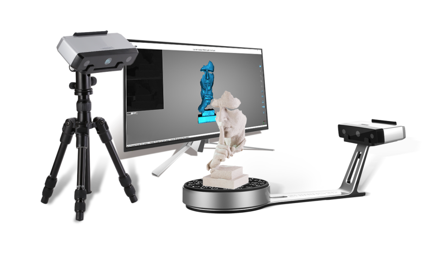
There are also 4 scanning modes. Single scan - can be useful if you are scanning an object from one side, for example, to obtain a relief. Manual scan sequence – scanning an object several times from different sides, turning it yourself.
Automatic turntable – speaks for itself. And background scan - to use this function, you need to remove the object of scanning, scan only the background. Then, during further scanning, the program will be able to automatically remove it from all scans. We will rotate the elephant manually on a black background, therefore it is not necessary to scan the background, but we will choose the mode - manual sequence.
Next, you need to choose how the object moves. Free movement, horizontal rotations or manual turntable. For this and most situations, free movement is fine.
Automatically register texture - with this function the scanner will capture not only the relief, but also the colors of the object with textures.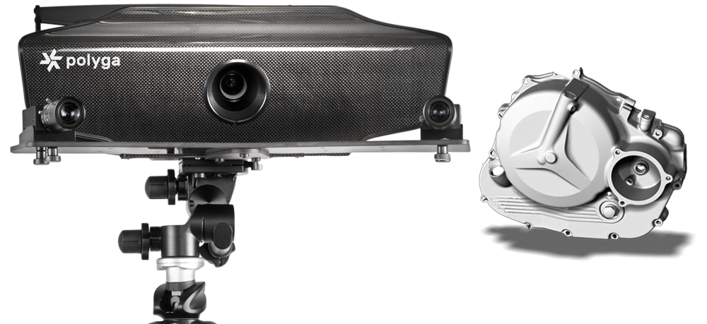 This way you will get a full color 3D model. This can be useful not only for beauty, but also will help the program in the future when comparing scans. But the scanning and processing time will increase slightly.
Below, in the "scan result" field, you can configure the smoothing parameters, checking the validity of fixed points, filtering and deleting parts that are smaller than the largest solid part. The manufacturer recommends not changing these parameters unless necessary. And then you can turn on the checkbox - Remove background. If the background was previously scanned, it will automatically be set.
Let's proceed directly to scanning. You can manually click on the scan button (or hotkey F5), rotate the object, and then click the button again. Or you can check the "Auto next scan" box, then the program will count a few seconds before automatically making the next scan. Moreover, if you move the object at this moment, the counter will automatically reset. Thus, the next scan will be made only when the object is stationary.
For this elephant, we will not scan the textures and set the next scan to automatic, so that you do not have to press the button every time. We direct the projector at the object so that the template fully illuminates it. And press the scan button. After each scan, we rotate the model a little so that the scans have enough common elements for subsequent comparison. And so a full circle. The manufacturer recommends taking 6-8 shots, but the more shots there are, the easier it will be for the program to match the scans and the more details it will capture.
After one full circle, you can raise the scanner on a tripod, tilt it from top to bottom and scan the object from a different angle to capture horizontal planes that were not in the frame.
The same can be done from below. If it is not possible to raise the scanner high or low enough, the object can be turned over by itself.
When scans have been made in all possible positions, you can click on the “end sequence” button.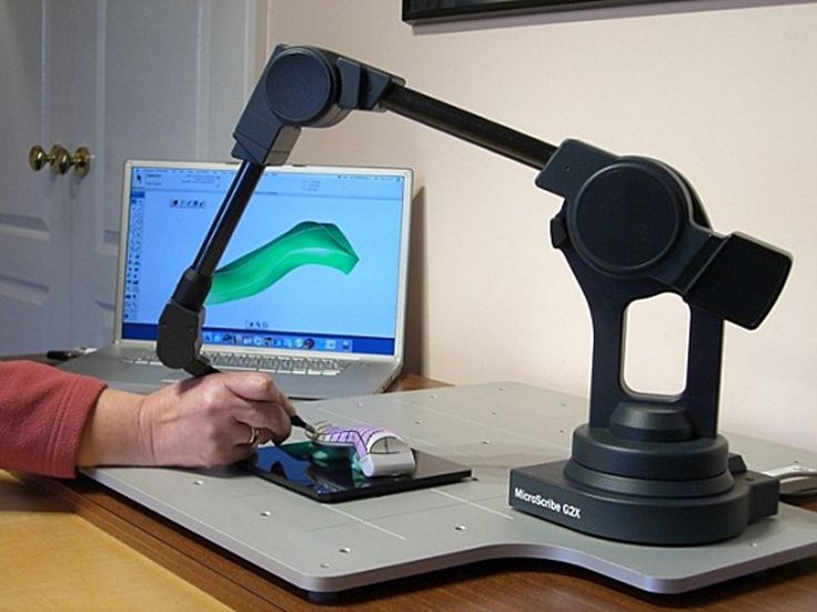 The program will automatically try to match all scans with each other. In most cases, scans match well, provided they have enough common shapes. If any extra fixed elements get into the camera lens, they can interfere with the comparison. Then, before clicking the “complete sequence” button, you need to go to the “merge forms” tab. In the clearing block, you can choose the selection method.
Select unnecessary objects and delete them by pressing the button with a cross in the same block, or by pressing the DEL hot key. And after that, return to the scanning tab and complete the sequence.
If automatic matching does not work properly, scans can be manually matched in pairs. To do this, in the "merge forms" tab in the "alignment" block, select "arbitrary".
Select two scans with common shapes, they will be matched automatically. In order not to display all the scans at once, you can click on the eye icon in the list of scans at the top. And click on the same icon next to the desired scans so that they are displayed.
If such a comparison did not work, you can check the "selection of a contact pair" checkbox.
This will allow you to manually mark the same elements on each scan, by which the program will navigate. You can enable "use texture" if the scan was done with textures. And also “use surface elements”, this will also improve the comparison, but also increase the processing time. Already aligned scans can be combined into groups, then when combined with the next scan, the program will use the group as one whole scan.
After this manual matching, you need to select the "global high-precision matching" alignment. The program will neatly and accurately fit previously aligned scans. Before high-precision alignment, it is desirable to divide the scans combined into groups back.
If some areas of the scanned object are not visible on the scans, you can always make a few more scans from the desired sides.
As a result, about 30 scans were made for this elephant from different sides, top and bottom.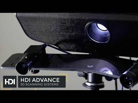 But keep in mind that this object is quite complex and dark. The camera was far from always able to see and evenly fix the surfaces. But as a result, it turned out to assemble a whole elephant from scans. The scan took about 20 minutes.
At this stage, this is a point cloud. Now you can assemble it into a full-fledged 3D model - mesh. To do this, we will use the "merge" block. There are 3 settings, resolution, sharpness and close holes. Resolution marks the quality of the final model, increasing this parameter greatly affects the processing time and the use of computer resources. Sharpness is responsible for smoothing. Reducing this parameter will make the model blurry and hide flaws. An increase, on the contrary, will make a clear model, but the shortcomings will become more noticeable.
The closure of the holes speaks for itself.
In most situations, the standard settings are sufficient. This is how the elephant ended up with the default settings. You can export the model in several formats - STL, OBJ, PLY and 3MF
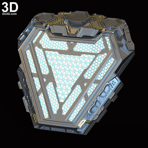
For the second test, I tried to scan a smaller object. Here is a dental impression printed on an SLA printer.
Dimensions are only 7.5x5x3 cm, which is almost the minimum for this scanner.
Of course, there is no special point in scanning what has already been printed, but for an example it will do. The result was a pleasant surprise, the quality was very good. Detailing is top notch. The scanner was able to see even the slightest transitions between layers, and printing flaws. Even though they are quite difficult to see with your eyes.
It is worth noting that the scanner perceives color changes on the scanned object as small changes in the relief. So, for example, there are several light scratches on these teeth. And on the final model, they look like protruding stripes. But all these shortcomings can be easily corrected with further post-processing, for example, in Meshmixer. Unfortunately, no 3D scanner gives a perfect result that does not require post-processing.
Only 10 scans were needed for this test, 8 from one angle, one a little higher and one a little lower.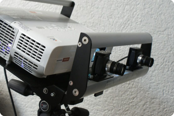
When scanning, especially for such small objects, the scanner is very sensitive to vibrations. Roughly speaking, even a printing printer standing a meter away from it can create sufficient vibrations, due to which waves are obtained on scans. Walking near the scanner at the time of scanning is generally contraindicated. Despite the fact that the tripod seems to be strong and reliable, the heavy part with the projector and camera is very sensitive to any vibrations. Due to the fact that our specimen does not have a turntable, we had to turn these teeth very carefully during scanning, without making sudden movements and almost without breathing.
In any case, the result of this test is very good. Considering that it took very few scans, they were matched automatically without any problems. Glued into the model quickly. In total, this scan took no more than 10-15 minutes.
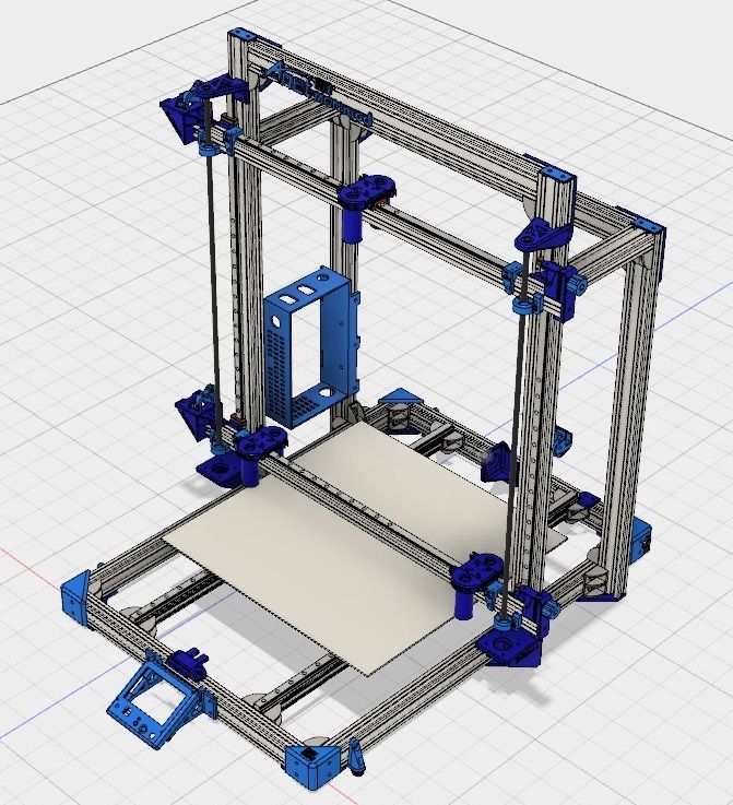
And the third test I did was with a larger part. This is a part of the intake manifold, also printed on an SLA printer, it was not possible to get a real part.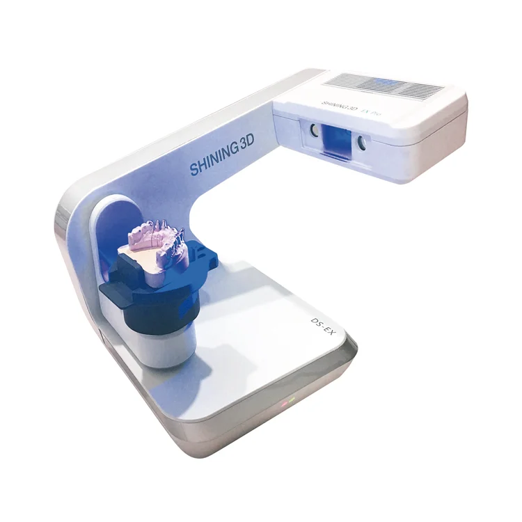
Its width is 34 centimeters, not the maximum for this scanner, but quite large. The detail is difficult to scan, has many thin elements, recesses and holes. It was really hard to scan it. Despite the fact that the turntable in this situation would not help. The part had to be twisted, turned over at different angles, and shown to the scanner from all sides. There was no black background of this size, so I had to scan on white. As we already mentioned, you can make the background automatically removed from the scans. To do this, you need to scan it without a model at the very beginning. The background is removed, but not always completely, small areas remain at a short distance from the model. They can be deleted without problems, but because of this time, the scan takes much longer. When scanning large objects, the accuracy is slightly reduced, since the projector and camera have to be placed at a greater distance and it is no longer possible to accurately fix small elements. But it turned out that after scanning the entire model and obtaining the general forms. You can always recalibrate the scanner with a smaller scale of the calibration panels pattern, scan individual areas closer and combine them with previously obtained scans. I was pleasantly surprised that even with such manipulations, all sizes are transmitted correctly and without distortion. The scans obtained after recalibration matched the original ones without any problems.
The result is, of course, not ideal. But worthy, given the complexity of the detail. In some places it was not possible to crawl with a scanner, their program finished drawing as best it could. It took a lot of time for scanning and processing, no matter how you lie, a total of 2-2.5 hours.
And finally, I scanned some more small objects with textures to show you how the scanner can capture colors and patterns. There is not much to tell about them, it was not difficult to scan them. So here are just a few photos.
What can be said in the end. The scanner can hardly be called easy to use. You need to understand the principles of its operation and the specifics of its use in different situations. Black, transparent and shiny objects need to be coated with a frosting spray, but this must be done with almost any 3D scanner. The software has great features and performs its functions quite well. But, as with the scanner itself, it requires certain skills, understanding of the capabilities and principles of operation.
I was pleasantly surprised by the quality when scanning small objects and the ability to additionally scan separate detailed areas for larger objects.
With proper skill, you can get very high quality 3D models with this scanner.
Lowrance StructureScan 3D Quit | LSS-3D | Authorized Dealer
Lowrance StructureScan® 3D allows anglers to see fish, their locations and bottom contours in stunning 3D.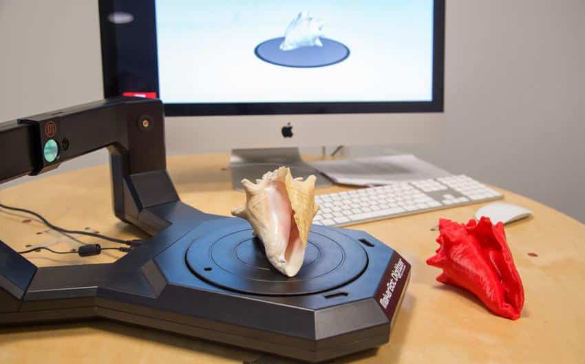 StructureScan® 3D scans the underwater landscape and fish locations to create high-resolution, 180-degree 3D images directly below your boat. With the help of unique image viewing technology, you will better understand where the fish are and where they accumulate in relation to your boat. When using the combination of the SideScan 3D Skimmer® side scan transducer and the StructureScan® 3D module, photorealistic, 3D images are displayed on the screen of your Lowrance HDS Gen3 fishfinder/chartplotter.
StructureScan 3D is powered by multi-beam sonar technology that scans underwater terrain and fish in stunning detail and converts the scanned material into high-resolution 3D images with 180-degree coverage.
Easy-to-understand sonar view
Viewing 3D images from any angle is done with Pan-to-Any ScanTrack™, touch control via on-screen commands makes preset viewing positions easy to use.
Quickly find key fish habitats
StructureScan® 3D makes it easier for anglers to locate fish, where they are in relation to their boat. By moving slowly over a wide potential fish area, within a 180-degree scanning range, anglers can quickly find key areas and hiding places such as sudden changes in depth, holes, ditches, rocks, weeds, logs, wrecks and more.
Outstanding side view clarity
To provide the clearest side view possible, the design of the StructureScan 3D sensor has been improved by increasing the number of sensors for greater image acquisition efficiency.
High Definition (HD) and Super Wide 3D Scan
Contours below the water surface can be shown on the sides of boats up to 180m deep to port and starboard, with incredibly detailed HD images. StructureScan® 3D provides several modes, including DownScan™ and HD StructureScan® 2D imaging modes, and a new, realistic 3D imaging mode. Using the preset virtual angle viewpoints or the ScanTrack™ pan/tilt control mode, you can fine-tune the view and perspective below your boat.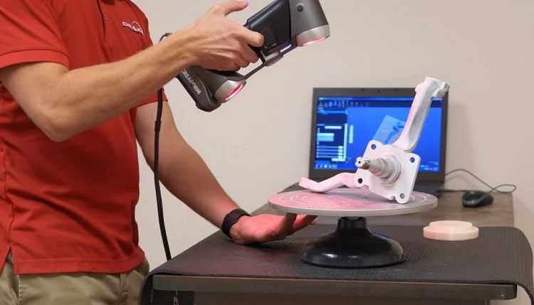 Using a combination of high definition (HD) and 3D images increases your understanding of where fish might be hiding and makes it easier to find a fishing spot.
Leading Edge™ scan results
Leading Edge™ provides a clear graphical representation of sonar beams where they intersect with bottom contours. The depth and range of the scanned area are shown as red fan marks directly below the boat. Leading Edge also includes a depth scale that, when zoomed in, shows more detail, giving you a better understanding of depth targets.
SelectScan™ Target ID
SelectScan™ automatically colors fish spots and captures objects in a color that contrasts with the selected color palette, making targeting faster and easier than ever before.
Vertical Gain Control
The vertical gain is a user-selectable scale that accentuates abrupt changes in vertical terrain and contour depth on the screen, making it easier to identify them in relation to surrounding underwater terrain.
 Vertical Enhancement makes even the smallest changes in depth more visible.
 Waypoint overlay
Reviewing fishing grounds, fish habitats and other bottom features is easy with the waypoint overlay feature. Use the keyboard icons to store a route waypoint at the boat location, or switch to cursor mode and store a waypoint over a specific target, fish feeding or hiding place.
Automatic 3D image adjustment
3D image settings adjustment is set by default depending on the configuration of your HDS Gen 3 and StructureScan 3D module. Sharpness and contrast adjustments can be made using the slider bar settings on the screen. The Clarity option reduces noise on the screen surface by lowering the sensitivity of the sensor near the surface. The Contrast option brightens/darkens the color palette to make it easier to identify fish and bottom structure.
| DownScan | |
Max.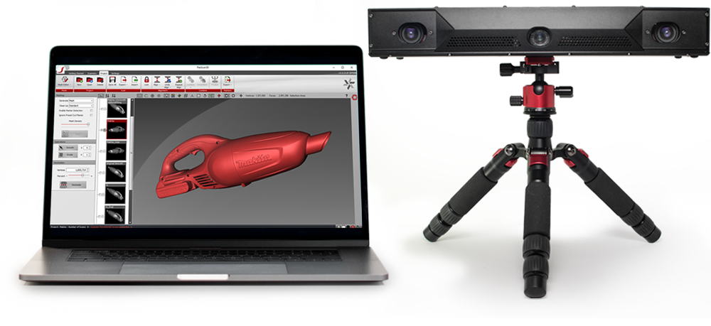 | |