Arduino mega 3d printer software
How to make a 3d printer with arduino at home - low cost
It is step by step guide to make an 3D printer at home using arduino mega. using this home made cheap 3D printer you can make 3D printed object up-to 200mm X 200mm Y 200mm Z
To make the frame of this 3d printer I have used easy available, low cost aluminium channel & did not used any 3D printed parts to make this printer. I tried to use as possible low cost but reliable materials. however I am satisfied with its result so you can make your own diy 3d printer using Arduino.
Generally popular Diy 3d printer using arduino mega is using old DVD drive,s stepper motors but this one is big 3d printer. The small DVD drive stepper motor can print only maximum 4 cm X 4 cm but this big diy 3d printer can print up-to 20 X 20 cm objects.
Here I will going to describe how I prepare the all mechanical part & software details which I have used
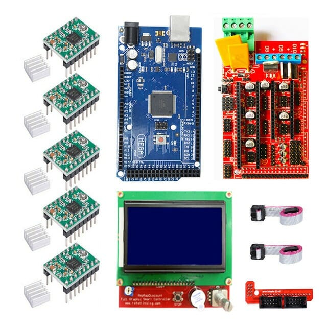
Arduino 3d printer kit & other parts from here ( Amazon India)
Parts need to make
1 . NEMA 17 Stepper Motor 4 Wire Bipolar
Step angle: 1.8 degree
Current: 1 a
Holding torque: 4.2 kgcm
Voltage: 2.4v
No of leads: 4
5 piece
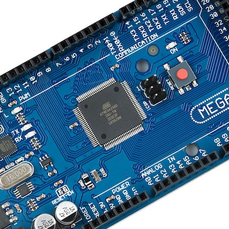
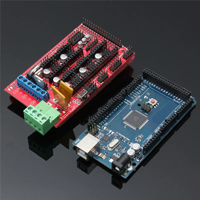
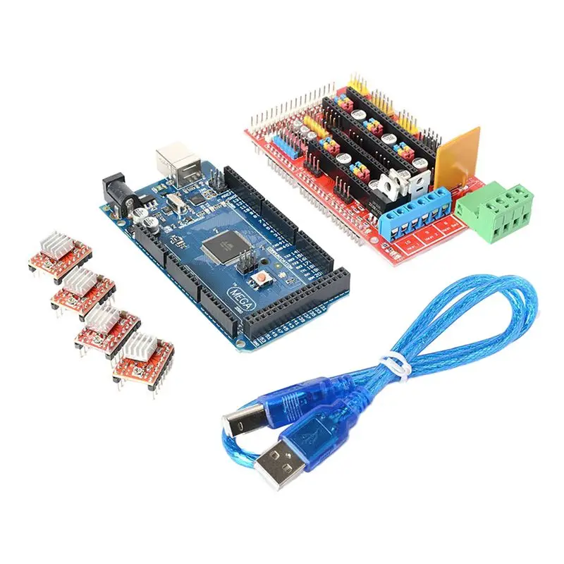
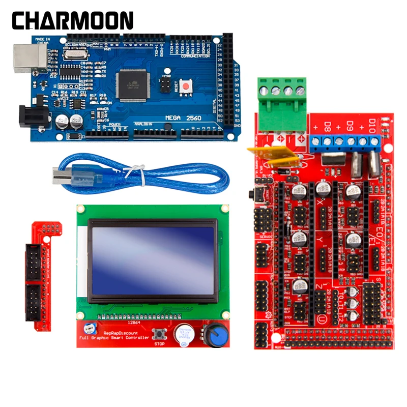
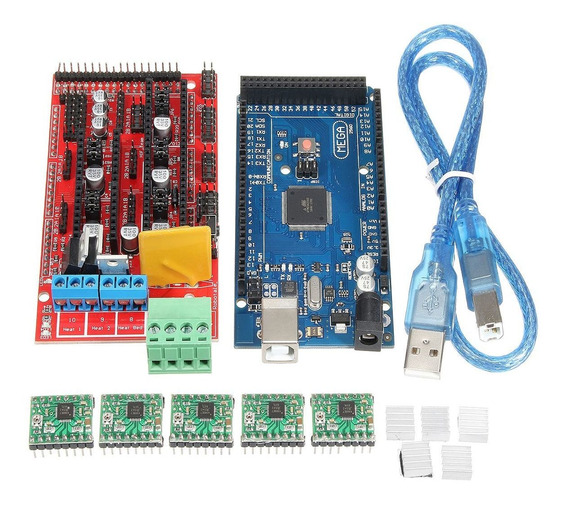
2 . Arduino Mega 2560
3. Ramps1.4 Shield
Ramps 1.44 A4988 Stepper motor Drivers with heat sink 4 piece
5. V6 J-Head Hotend Bowden Extruder Full Set with Fan
12V Heater, Ptfe Tubing for 0. 4mm 1. 75mm Bowden for 3D Printer
6 .Mk8 Extruder Aluminium Block DIY Kit: Right Hand Type
7. SMOOTH ROD M8 500 MM – 4 pcs
8. T8 Trapezoidal Lead Screw 8MM Thread 8MM Pitch 300MM
9. Flexible Coupling Coupler 5mm8mm25mm (2Pcs)
10. 8 Pieces LM8UU 8 mm Linear Ball Bearing
11.2 Meter GT2 6MM Open Timing Belt
12. 2 Pcs 20 Teeth Pulley 5mm Bore
13. PCB Heat Bed MK2B 12/24 Dual Power 214 mm 214mm
14. Radial Ball Bearing 8x22x7mm 608-2RS Ball Bearing – 4 pcs
15. End stop switch – 3 pcs
16. Aluminium channel 2 inch X 1 inch – 12 ft
17. Plastic clip board
18. 20 cm X 20cm glass
19.20cm X 20cm ply wood
20. Screw ,spring ,Zip tie
21. Aluminium L clamp 1″ X 1″
22. 12 Volt 20 amp DC power supply .I am using a modified old pc ATX power supply
23. 1.75 mm filament
Please watch part 1 for all parts details & making frameSoftware need
Arduino IDE – Download here
Marlin firmware – Download here
Pronterface software – Download here
Making 3D printer frame using Aluminium channel –
We have to cut aluminium channel using hacksaw
Dimension – 53cm – 3 pcs
45cm – 2 pcs
43 cm – 2 pcs
10cm – 2 pcs ( for bed)
join all aluminium channel using L shaped clamp This video can help you
After making frame we have to install Y axis motor at front side of the printer.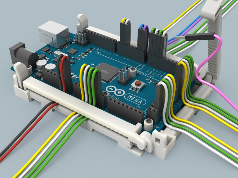 I have used zip tie to fix motor.
now install 608 bearing using L shaped clamp & install GT2 timing belt to GT2 timing pully
To make a smooth liner motion I have used here 2 pcs 50cm – 8mm – smooth rod & 2pcs 10cm aluminium channel is base of the printer Y axis bed.
making Y axis ,X axisFor Z axis we have to use two nema 17 motors & two
Trapezoidal Lead Screw connected by
Flexible Coupling .
For making X axis structure I have used cheap plastic clip board you can also use acrylic sheet.
After assembling Y,Z& X axis we have to do assembly
Mk8 Extruder block ( here is MK8 Extruder assembling )
I have used 3 minimum position mechanical end stop switch. you can also use 3 pin end stop.
My end stop switch pin is NC (normally closed ) & NO (normally open) but 3 pin end stop switch connection is may little bit different.
Wiring of 3D printer
We are using 12v 20 amp power supply .please use minimum 1mm wire for connection heat bed & hot end
for temperature sensor & End stop switch you can use thin wire .
place ramps board above arduino mega &
we have to set jumper for micro stepping ( please watch this video ) Then place 4 step stick on ramps board 3 step stick will drive 3 axis (X Y & Z) Motors & other one is for Extruder motor
We are using Ramps 1.4 & A4988 as arduino 3d printer controller
Wiring diagram of home made arduino 3D printer wiring & resultDiy 3d printer software
Check flowing article for Arduino 3d printer code
We are using marlin firmware for this 3D printer.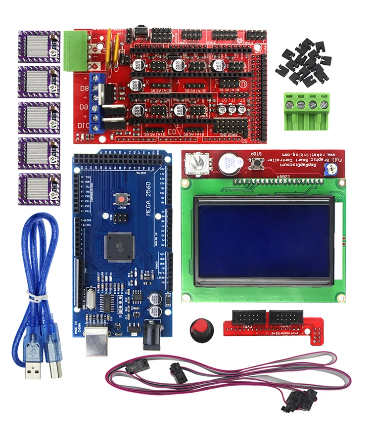 Here is details of marlin configuration.h
How to Make a 3D Printer with Arduino – ELEGOO Official
Source: https://unsplash.com/
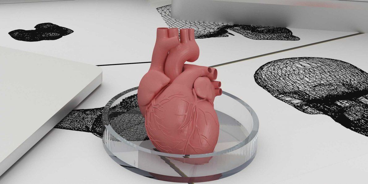
3D printing technology is wide, despite having been around for a little over 30 years. The improvements the technology has been undergoing are all slowly pushing it slowly towards a realm where everyone will be able to access simple 3D printers at low prices, getting the ability to make whatever they want from the comfort of their own homes. One of the most utilized 3D printing concepts is the Arduino.
Arduino is an open-source electronics platform that is based on easy-to-use software and hardware. They are boards that have the ability to read inputs, activating other machines, among many other automated functions. We are going to explore how to make a 3D printer using the Arduino platform, the benefits of having a DIY Arduino printer as well as some comparisons with other official models that are in the market.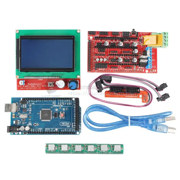
Why Arduino?
Source: ELEGOO
There are perfectly good reasons why Arduino is used extensively in most DIY projects of making 3D Printers. The first Arduino kit was created in 2005, and in the last 15 years, it has become a very reliable software for people who are looking to create their own 3D printer. The following are reasons why they are the best choice for DIY 3D Printers.
- It is cheap: Arduino is easily accessible and affordable, and the price keeps going down as more improvements are being made in the 3D printer sector. A simple Arduino kit will set you back just about $24, which is well within the affordable range of most people.
- Easy to use: An Arduino kit is usually ready to use straight from the box. The kit comes in a complete package that includes a 5V regulator, a burner, a microcontroller, a serial communication interface, LED, and headers. All you have to do is plug it into the USB port of a computer, and you are ready to roll.
- Wide range of codes: Arduino comes with a huge library of codes that are already present in the Arduino itself. The kit literally sets itself up in a number of ways, and in the event, you run into obstacles, troubleshooting is not that complicated to pull off on your own.
- Large community: There is a huge number of online forums that are full of people who use Arduino, and this provides new users with a platform where they can get help immediately from other users who have had the experience already. Every trouble you may run to will have a solution, and this makes Arduino a very resourceful tech.
- Cross-platform: Arduino is a cross-platform software that can be used on Windows, Linux, and Mac. This makes it resourceful and unlimited in many ways. You don't have to buy a particular computer to run it; all you need is to get a computer with the right specs. You will be making your 3D models in no time.
Making a 3D Printer with Arduino
The process of making a 3D printer may look daunting for those that have never used it before, but if you are a newbie to the game, the process is a little easy. The following are some of the stages that are used in making a 3D printer using the Arduino platform.
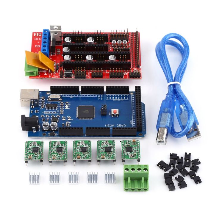
To start off, you have to start collecting the components and supplies to start yourself off. The following are the boxes you have to tick off.
- A ramps 1.4 controller board: This is used for interfacing purposes like connecting the end-stop switch, the heatbed, the stepper motor driver, the hotend, and a host of other components with the Arduino.
- Optical end-stop switch: This is a sensor switch that comes with two markings. NO or NC (Normally Open/Normally Closed). They function as triggers when the XYZ axis of a printer reaches its endpoint.
 They can be used at any time to stop and start movements.
 - NEMA 17 stepper motor: This is a motor that allows the user to set the speed of revolutions for the movable parts of the printer. The average motor has about 200 steps, but you can get a bigger one.
- PCB heatbed: This keeps the extruded plastic parts warm at all times to prevent them from warping.
- Power supply: A 12V/20A power supply is needed to run a simple kit. These power metrics are the minimum you should go for success.
The Process
With all the important components in place, the next step is to start making your DIY 3D printer. The stages involved include the following.
Step 1: Build the Frame
Source: https://www.pinterest.com/
The frame is the outer casing that houses the entire contraption, and it can be made to any size depending on what you need. The materials used to make the frame also vary, and the decision comes down to personal preference.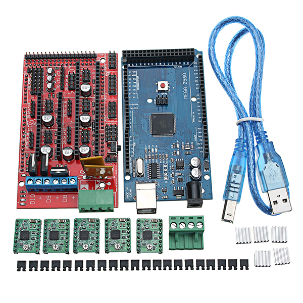 The most compliant used materials are aluminum, acrylic, or hardened plastic. You have to make sure that all the parts fit well and there are no loose parts. It is important that the frame is solid because it will be providing support to the other parts that are added.
Step 2: The Display
Source: https://www.pinterest.com/
An LCD display is important as it relays the information you need to know about the printing process in the absence of a computer connection. You need an aluminum sheet for this process with some holes and screws, and nuts. You have to cut out space into the aluminum sheet through which the display screen will pop out of. Once you have all that art covered, connect the necessary display cables from the inside leading out, waiting for the main part of the printer to be installed.
Step 3: Preparing the Y-axis and Z-axis
Source: https://www.pinterest.com/
You need an MDF base that houses a cooling fan to reduce the heat produced by the stepper motor.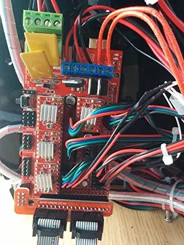 These are done by adding two wooden cuttings for the X-axis placement. This is followed by making the Y-axis placement that’s supposed to be at 90 degrees from the X-axis. Hold them in place using glue, or you can simply use some screws.
You have to add a stepper motor to the X-axis using two pieces of sliders of any length that can fit within the structure. Once the slide is screwed in place, fit your wooden mount for the hot-end, the cooling fan, and the PTFE tube. With these two in place, your 3D printer is starting to take shape.
Step 4: Preparing the Bed
Source: https://www.pinterest.com/
The bed is one of the most important parts of the entire machine. It is the part that provides the platform upon which the model being printed is made. It can be made out of glass or an acrylic sheet held down by screws. You can have the base supported by another solid material. Once all that is done, place the bed on the Y-axis, and it is ready to start rolling.
Step 5: Make the Connections
Source: https://www.pinterest.com/
The next part involves making the wiring connections of all the components that you have already laid down. All the electrical components like the ramps. The drivers and the power supply have to be linked properly for them to run as designed. To avoid entangling the wires, make sure you deal with one connection at a time, ensuring that they don’t cross each other unless there’s no other way around it.
Step 6: Make Alignments
The bed you created earlier has to align with everything else, or you may experience a lot of trouble getting the models right. Start by aligning your bed, rotating it clockwise and counterclockwise until you create some space between the hot-end tip and the bed.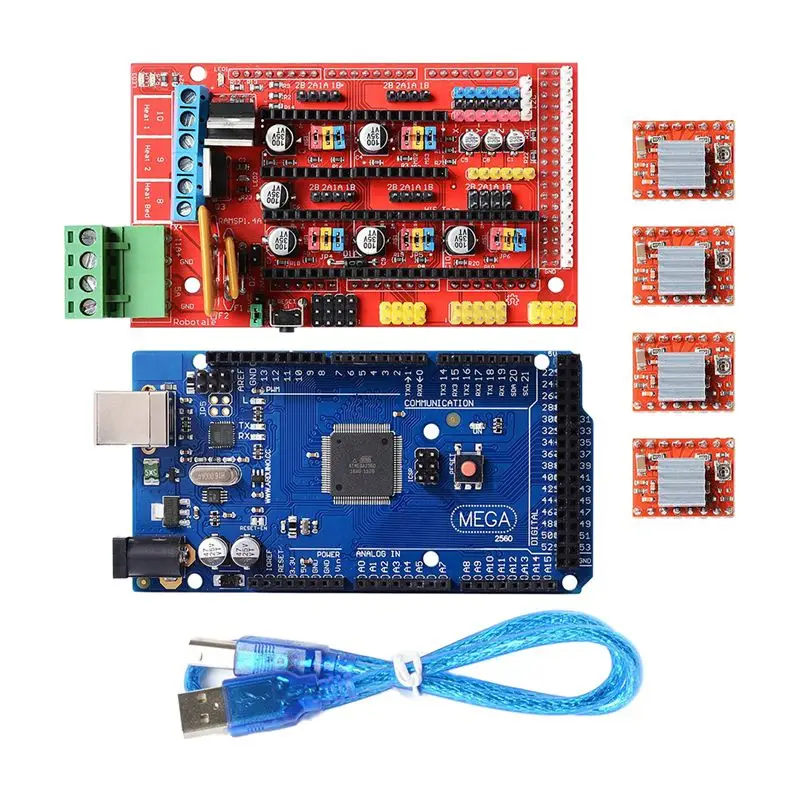 The margin of error should be between 0.5mm to 1mm. Anything larger than that will have the printing guy misfiring.
Step 7: Programming
Source: https://www.simplify3d.com/
With all the hardware installed and the electrical wiring and cabling in place. It is time to install the brain of the whole operation. Programming the 3D printer doesn’t require you to code from scratch. The software simply needs to be installed on the computer connected to the machine. This should not take too much of your time.
Step 8: Run the Machine
Once the 3D Printer program is installed and the components are set, it is time to run the machine for the first time to finger out if it is working as designed or whether it needs some more tinkling.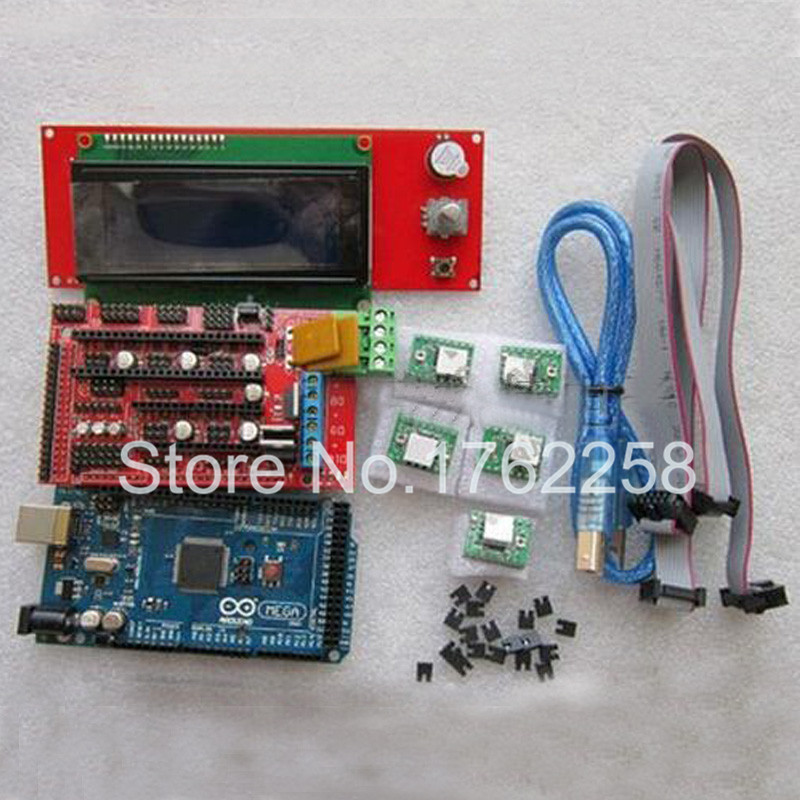 The number of software that you can use to model your objects is many; you are free to choose the one that works best for you and switch the machine on for the first test run. Make sure the fan is working to deal with the heat.
Building Your Own 3D Printer. Is It Worth It or Not?
Source: https://www.pinterest.com/
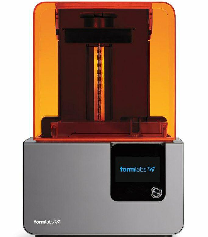
Having established that making your own printer is possible, and having seen the process and what it takes to attain success, the question now is, is it worth the trouble? High-quality 3D printers cost less than $400 these days, and as much as making your own brings pride and cuts costs significantly, how do DIY 3D printers hold against professionally manufactured ones? To better get to the answer, the following are the pros and cons of DIY 3D Printers.
Pros
- DIY Kits are cheap and easy to access. For as little as $25, you can have a full package that can help you set up your own printer.
- DIY projects will make you understand 3D printing more, adding to your experience on the subject, which increases your level of knowledge and chances of success if you ever think of getting fully immersed into the industry.
- It is fast if you know what you are doing and you have all the materials you need in one place.
- There’s a huge online community of DIY 3D printer enthusiasts, and these platforms provide resources that help people learn more about 3D printing.
- The kits come with instruction manuals that anyone can follow and hack the construction. They are very easy to use.
Cons
- You still need some basic knowledge of assembling electronic parts in the right way to be able to put 3D printers together. You can’t wake up one morning and decide to make it because you feel like it.
- They are not as high quality as those that have been manufactured by proper 3D makers. The parts found in DIY printers are too rough and rudimentary for the machine to produce superior products.
- There are very many things you may miss along the way, and this can end up frustrating you later on as that will force you to retrace your steps backward until you find the source of the malfunction.
 That will waste a lot of your time.
 - You will always need to buy more parts the furthest along you go. There’s also the disadvantage of the parts falling apart since they're not well optimized for such an intense process. You will need replacements much faster.
- There are limitations when it comes to software configurations and upgrades since the hardware is not optimized for the software you may choose to go with. You may end up using the same software for years, and that will limit the things the printer can pull off.
Roughly, you may end spending between $100-$200 making your own DIY 3D printer. That cost may be cheaper than the standard prices for a professionally made printer, but when you weigh the strengths and weaknesses of each, the DIY is at a disadvantage. Therefore, on the question of whether to go for a DIY 3D printer or simply buy a good one, the answer comes down to what you plan to do. If the thrill of making your own is what is important, then take the DIY route.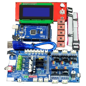 But if you want to get some professional work done, then you are better off adding that extra $200 and getting a proper 3D primer with accessories and software updates.
There are some things you have to pay attention to when going the DIY route, factors that will determine the success or the failure of your project. Some of them include the following.
- The size of the printer you intend to make
- The printer type (Cartesian vs. Delta)
- Extrusion type
- The cost
- Availability of liquid polymers
- Software compatibility.
Before you embark on setting anything up, you have to first determine whether all the conditions mentioned above are met; only then will you get anything done by coming up with a good plan.
Conclusion
DIY 3D Printers are effective if they are made in the right way, and there are many methods of creating them. Finding a good Arduino kit could be the difference between having a 3D printer that world and one that keeps breaking midway.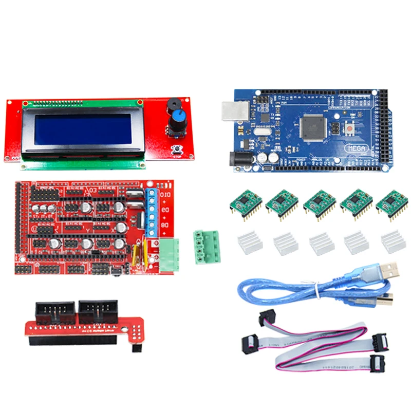 Ensure you do some background research before having to gain more knowledge before committing yourself to an ambitious project like this one.
For more information on how 3D printers work, the accessories they need to function properly, and the current trends in the industry, check out our website, and you will have access to a huge pool of resources and expert advice.
Self-assembly of a 3d printer or purchase of ready-made construction equipment. ON. Part 2 / Habr
In the first part, it was shown and told how to assemble a
3D printer. Now, it's time to bring the mechanical marvel to life with software, brains and wires.
For this I used open source free software: Repetier-host (to connect the computer to the 3D printer control board) and Arduino IDE (to work with microcontroller firmware). And the 3D printer itself. The intricacies of setting up this software will be discussed in this part:
The Mastertronics control board has an Arduino MEGA 2560 microcontroller on board, through which it communicates with the computer and controls everything connected to this board, as in the figure:
assembled structure (Part 1)
2) We connect the mini-USB cable to the Mastertronics control board and to the computer
3) Next, flash the microcontroller with Marlin_MC5 9 firmware0015 (version I use in my printer here)
4) Run the Repetier host software on computer
5) Set the printer parameters in the Repetier
software 6) Establish a connection with the printer
7) Connect the power to the control board
8) We check the operability of the control board and the electronics connected to it
9) If necessary, we make changes to the firmware Marlin
Let's start from point No.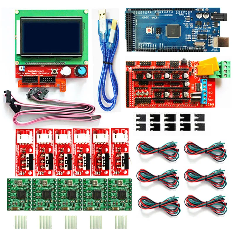 3
3
To do this, you need to run the Arduino IDE program, in the tools tab, select the Arduino Mega 2560 board, ATmega 2560 processor and com port.
Open the file with the downloaded Marlin.ino firmware, click the --> Download icon, wait while it compiles and loads into the microcontroller ...
Now go to step number 4 .
Here you need to set the com port, baud rate and cache size
As well as all the parameters of the printer, extruder and print area:
Printer settings
After that, you can safely press the key with the fork icon-> Connect the printer and move ears steppers. This can be done in two ways: Using the buttons on the control panel, or by sending G-code commands:
Pay attention to the Emergency Stop button highlighted in yellow circle.
After a successful connection with the control board, you can apply power to it and send a parking command to all three G28 axes, or press the button with the image of a house without a letter inside.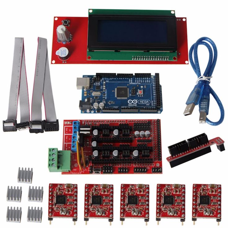 If the motors and limit switches are connected correctly, then the printer will move each axis until the limit switches are triggered. Thus, zero coordinates for all three axes (Home position) will be set. This is what it means to be confused.
If something goes wrong, press the emergency stop button, turn off the power, think, check the correct connection of motors and limit switches to the board, installed jumpers under the drivers. If everything is connected correctly, but does not work properly, then open the Marlin firmware on the Configuration.h tab and check the logic for triggering the limit switches in the code lines:
const bool X_MIN_ENDSTOP_INVERTING = false; // Set the value to (true or false) true or false to invert the endstop logic.
const bool Y_MIN_ENDSTOP_INVERTING = false;
const bool Z_MIN_ENDSTOP_INVERTING = true;
const bool X_MAX_ENDSTOP_INVERTING = true;
const bool Y_MAX_ENDSTOP_INVERTING = true;
const bool Z_MAX_ENDSTOP_INVERTING = true;
I had problems with the direction of movement of the axles when parking, so I had to change the logic of the limit switches in the firmware code.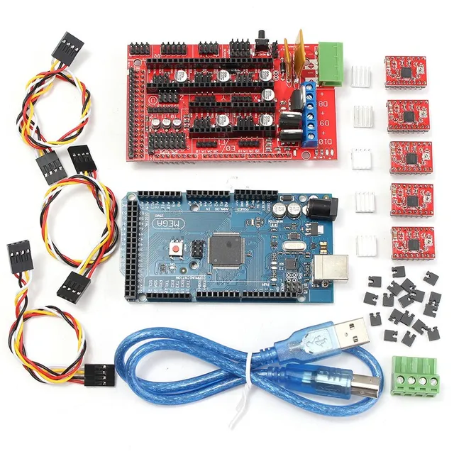
Next, you can proceed to check the performance of the extruder.
To do this, you need to set the temperature to 100 degrees and monitor the readings of the temperature sensor. If everything is ok, then we try to heat up to a temperature of 200 degrees, then insert a plastic thread and push through a few tens of centimeters using the manual control of the extruder in the Repetier program. I had no problems at this stage:
This completes the preparation of the printer software. Then you can move on to the third fascinating part - 3D printing itself, which has its own subtleties in setting up, which you need to master in order not to print such products:
slicing" of 3D models for printing, about the requirements for 3D models and why cannot be so easy to take and calibrate a 3D printer.
Connecting electronics for 3D printer rapms 1.4 and arduino mega 2560 Graber i3 plywood printer
Assembling a 3D printer, and in particular one of the most important parts, connecting all components to the arduino mega board and ramps 1.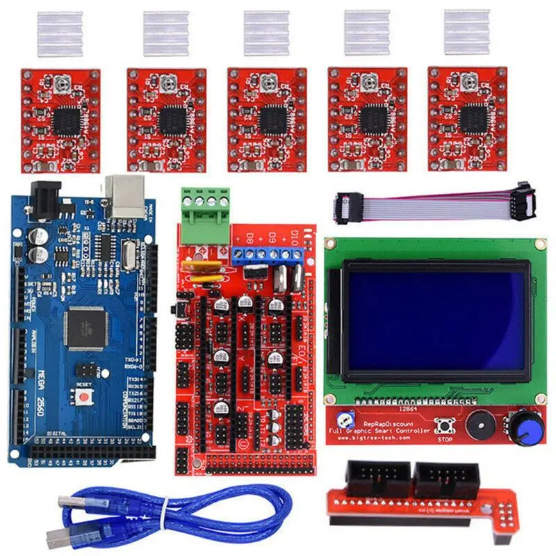 4.
4.
RAMPS 1.4 is a shield (add-on) for Arduino Mega 2560. Arduino converts G-codes into signals and controls the 3D printer through the power part - RAMPS 1.4.
RAMPS 1.4 is shield (add-on) for Arduino Mega 2560 . Arduino converts G-codes into signals and controls the 3D printer through the power part - RAMPS 1.4.
Board RAMPS 1.4 is worn over Arduino and all connections except USB are made through it. The 12V power to the Arduino is supplied via RAMPS 1.4.
Connection diagram of the elements of our 3D printer
For clarity along the axes:
0049 12V 15A . To use one pair of wires from the power supply, you can solder a jumper to the pluses, the minuses are already connected.
Pinout . Colors can be mixed up, but pairs are easy to call with a multimeter.
Stepper motor works through driver .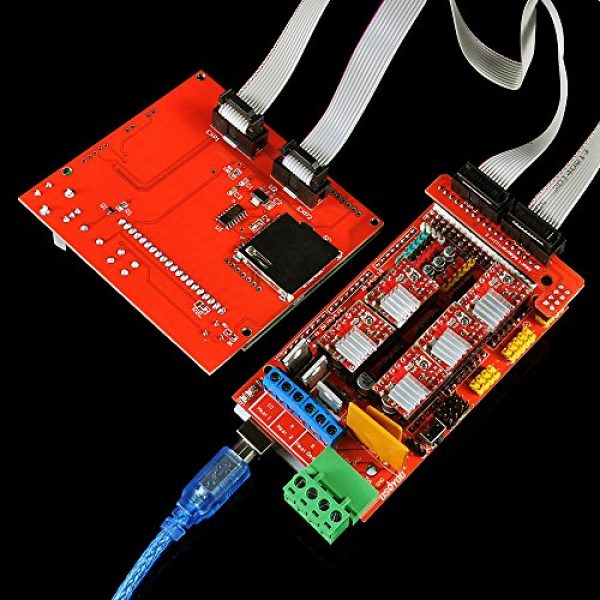 They are also called StepStick. For RAMPS 1.4 , two kinds of drivers are released A4988 and DVR8825 . They differ current issued to the stepper motor and the minimum microstepping . Be sure to use a heatsink. Airflow is desirable. And if the table is powered not through a relay, then airflow is required.
The current on the driver is adjusted empirically by driving the 3D printer at high speed in all coordinates. It is considered optimal when stepper motors no longer hum and do not skip steps yet.
A4988
Maximum current 2 A
Minimum microstepping 1/16 stepping
Current adjustable by trimmer. Clockwise - increase current.
RAMPS 1.4 microstep setting
DVR8825
Maximum current 2.2A
Minimum microstep 1/32 step. Theoretically, it gives greater movement accuracy.
The current is regulated by a trimmer. Clockwise - current reduction .
Jumper microstepping on RAMPS 1.4
The microstepping jumpers on the RAMPS 1.4 are under the stepper motor drivers. Commonly used A4988 micro-pitch 1/16 - all jumpers set to .
Z-axis motors can be connected:
- in parallel - each plug in its own socket. This is a standard connection to RAMPS 1.4 . There can be problems with motors out of sync if there is a difference in the resistance of the motor windings.
- in series according to the diagram, one plug. There shouldn't be any problems with serial connection.
- Limit switches (limit switches, endstop, limit switch).
The most commonly used are optical and mechanical limit switches. You can find out the status of the limit switches with the command M119 .
Location of limit switches Connection of limit switches X-axis limit switch Correct connection of mechanical limit switches in position MAX . Optical limit switches use additional positive contact . Thermistor connection.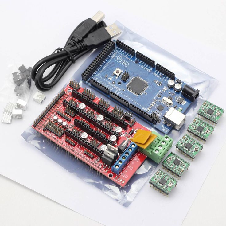 Usually they put 3 limit switches in position HOME and soft limit movements in firmware . The rest of the limit switches are designed to fail, but the step switches are weak and do not cause damage, they simply skip steps when they reach an obstacle. And along the Z axis, for Mendel90 , the nuts should be unscrewed from the carriages at the pressure of the hotend on the table .
 Thermistor can be tested with multimeter as resistor . ( I connected it to a multimeter - 87 kOhm. I clamped it with my fingers - the resistance began to fall, it does not stand still at all. )
Table thermistor and hot end thermistor (hot end) .
Heated table connection via relay.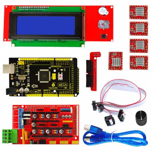
Stage temperature depends on current supplied to it. The current strength depends on the resistance of the stage, the size of the wires to the stage and the power of the power supply. And also on the quality of the thermal insulation of the internal cavity of the table.
Car relay connection diagram (12V 40A) Hot end heating connection. Fan connection for software-controlled blowing of the workpiece. Connection for hot end cooling fan, lighting and other 12 volt consumers.
Relay is installed to unload the power transistor and reduce the heating of the electronics board, in general for reliability . Or for dividing into two power supplies - electronics plus a hot end and separately for heating the table (you can increase the voltage and speed up the heating).
Connect to the RAMPS power connector. Connecting the LCD control panel (screen).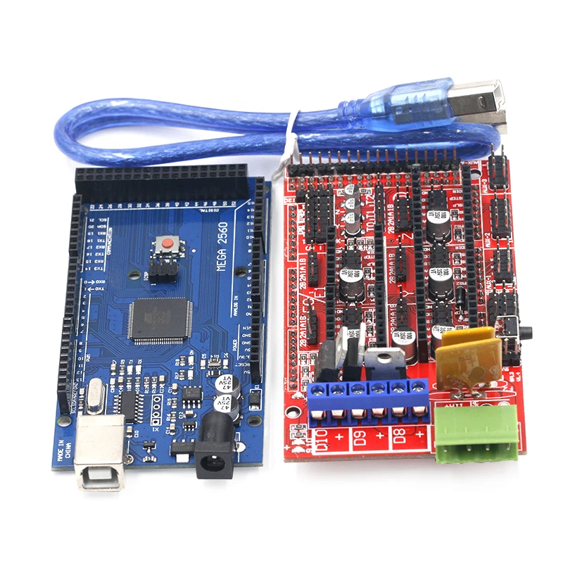
On the back we see two slots for connecting cables, an SD card slot and a brightness control.
Connection to RAMPS 1.4 is through an adapter. The sockets are also signed EXP1 and EXP2 for correct connection. - See also videos:
- First part of assembly
-
- Printing extruder assembly
-
- Part 2 mechanics:
-
- Scheme for assembling the rear printer + links to Aliexpress spare parts
- Engines nema 17 (need either 39 pieces +2 28 х 9016 , or 5 pieces) /ali.pub/1qr6jk (by the piece)
- Motors for the Z axis 28BYJ-48 http://ali.pub/1qr6qd
- Display http://ali.pub/1bhi2m
- Arduino mega 2560 http://ali .
 pub/1bhigt
 - Hot Desk http://ali.pub/1fkj3y
- Nozzle http://ali.pub/1bhiyp
- Thermistors http://ali.pub/1bhj5i
- Guide tube for plastic http://ali.pub/1bhj90
- Extruder http://ali.pub/1bhjfm
- Limit switches 4 pcs http://ali.pub/1bhjlu
- Belt + 2 pulleys http://ali.pub/1bhjpq
- Nema17 motors (4 pcs) http://ali.pub/1bhjuz
- Stud with nut http://ali.pub/1bhk0f
- Power supply 12 v 29 A http://ali.pub/1bhk87
- Plastic consumables http://ali.pub/1bhkhc
- Files downloaded here for laser cutting https://github.com/sgraber/Graber
- Z-axis motor adapter 28BYJ-48 https://www.thingiverse.com/thing:150896
- Geek channels:
- ➤ VK - https://vk.com/denis_geek
- ➤ VK - https://vk.com/club_arduino
- ➤ VK - https://vk.com/chinagreat
- - https://vk.com/solar_pover
- ➤ VK - https://vk.com/my_vedroid
- ➤ Facebook - https://www.
 facebook.com/Danterayne
 - ➤ Youtube - http://www.youtube.com/c/Danterayne
-
- ★ My partner with Aliexpress ★
- http://ali.pub/1j9ks1
- ★5 discount with any shopping on Aliexpress! ★
- http://ali.pub/1lx67o
- ★ Useful browser app for cashback ★
- http://ali.pub/1lx637
Related articles
TFT Nextion NX3224T024 example with Arduino Leonardo
In this example, we will try to display two coordinates of the position of the joystick connected to the Arduino on this screen as two fields for displaying numbers, as well as a graph with two feathers.
I once ordered these scarves for myself on Aliexpress:
TFT Nextion NX3224T024 - clickable
Arduino Leonardo - clickable
based on MAX30100 analyzer board, 0.9 used for visualization1 inch OLED display to report heart rate and oxygenation level.
Both used devices have a two-wire I2C interface, which reduces the number of wires for connection and also simplifies the circuit.