Structure core 3d scanner
Structure Sensor - 3D scanner for orthopaedics
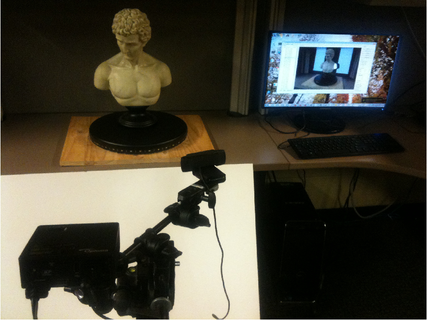
Structure Sensor + CapteviaPlus, a portable, versatile and easy-to-use solution for 3D digitalization of the human body.Structure Sensor is the first of its kind applied for orthopaedics.
Attached to an iPad, this 3D sensor turns your tablet into a 3D scanner for your patients. It is portable and works without cables or PC. No training needed.
Compact and highly accurate: +/- 4 mm at a distance of approximately 40 cm. Its infrared technology is safe and painless (Class 1 laser).
CapteviaPlus application, designed especially for the orthopaedic industry makes Structure Sensor even more efficient. The two combined provide a complete, portable and affordable digitalization solution.
Request a demonstration
Benefits
Structure Sensor is easy to learn and practical for use by any team of professionals.
Light and compact
The sensor + iPad together weigh less than 450 grams. Ultra-portable and adapted for travel. The ideal mobile tool.
Accurate
Structure Sensor scans from a distance of 40 cm (accuracy +/-4 mm). Easy to handle for taking 3D measurements.
Compatible with CapteviaPlus
Structure Sensor works with CapteviaPlus application, both developed by Rodin 4D and specifically designed for the orthopaedic industry. Together, they are an affordable and portable digitalization solution.
Highly performant
Its infrared technology (Class 1 laser) is industry widely recognized as safe and painless with outstanding performance.
En savoir plus
SOFTWARE AND APPLICATIONS
CapteviaPlus with Structure Sensor for a unique digitalization experienceSimple interface
Intuitive / scanning navigation in less than 3 clicks.
Higher precision scans
Specific selection of the parts of the body to be scanned for even more precise results.
Automatic scanning
No adjustments needed to get started / predefined integrated configuration optional according to type of scan.
Saved locally
Files are saved directly on the iPad, in full compliance with the GDPR.
Specifications
| Technology | High quality IMU / extra-wide-angle camera |
| Weight | 500 g |
| Connection | USB 2.0 |
Production capacities
| Corsets | 1.5 min |
| KAF orthoses | 3 min |
| Seats | 1 min |
| Tibial prostheses | Not recommended |
| Upper limbs | 2 min |
| Cervical orthoses | 2 min |
| Foam layers | 1 min |
| Knee braces | 2 min |
| Foot orthoses | 15 s |
Check out the Rodin4D product catalogue
Download
RODIN4D SOLUTIONS
Related products
Discover the range of Rodin4D products available to manufacture your devices.
SOFTWARE AND APPLICATIONS
CapteviaPlus
The app for iPad compatible with Structure Sensor
SOFTWARE AND APPLICATIONS
Neo
Neo, the Rodin4D CAD/CAM orthopaedic software
Are you interested in this product? Contact us.Our experts are available to answer your questions and provide additional information.
Contact us.
Infrared 3D scanner for iPad "Structure Sensor Pro for iPad" for health care has been released (July 2021)
April 2021, 8 TEGARA Co., Ltd. Hot topics now, engineering, Robotics, Sensor technology, Development kit / electronic work, Overseas Products What's New (Unipos), Version upgrade information
Infrared 3D scanner for iPad for health care "Structure Sensor Pro for iPadHas been released.
A compact 3D shape scanner (IR camera) for iPad / iPhone designed for use in iOS products, improving the Occipital Structure Core and Structure Sensor (Mark II) platforms and providing medical professionals. It is newly built to meet the needs for healthcare such as.
With the Structure SDK, which enables accurate, consistent and high-level scanning, and the various applications that support it, it includes medical professionals, iPad users, iOS developers, and homeowners (real estate related). It can be widely used.
About Occipital's Structure Sensor
Occipital's Structure Sensor uses a non-contact infrared irradiation method (a technology that irradiates and reflects infrared rays to measure the shape), which enables 3D capture with higher accuracy than a contact digitizer.
Structure Sensor Pro replaces Structure Sensor (MarkII), and you can choose the camera that suits your purpose from the two lineups.
- Structure Sensor Pro: For health care New!
- Structure Core: AR / VR SLAM for robot vision
* Occipital has 3D scanning for health care using Structure Sensor Pro and Structure SDK, andCanvasiOSWe specialize in 3D capture for home improvement using applications and 3D scanning services. |
A global shutter type camera built for healthcare.Best-in-class performance, improved integrity between units and scans, and consistent, high-quality data acquisition.It is useful for scanning and modeling environmental spaces such as rooms and body parts.
Package contents
- Structure Sensor Pro body (with bracket adapter)
- USB cable for charging
- USB-type C cable or Lightning Cable
- Screwdriver and screw
- iPad bracket *
* You can select the type of bracket for fixing to the iPad from iPad Pro, iPad, iPad mini, and iPad Air.
Brackets can be shared by each Structure Sensor.
Main functions
- Works on all iPads released after 2015
- GLOBAL SHUTTER
- Can be used indoors and outdoors
- Built-in original battery (iPad battery life can be maintained) *
- High quality and accurate scanning
- Maintains small size and light weight (same size as Mark II)
- Calibration according to industry standards
- Structure SDK (iOS) with out-of-the-box API
* You can achieve the longest runtime by using it with an iPad that supports USB Type-C.
Other
- Skanect Pro (3D scanning software) is not supported
- All accessories that work with Structure Sensor (Mark II) are compatible with Structure Sensor Pro
- Structure Sensor Pro works on iPhone
(iPhone 7, iPhone 7 Plus, iPhone 8, iPhone 8 Plus, iPhone X, iPhone XR, iPhone XS, iPhone XS Max, iPhone 11, iPhone 11 Pro, iPhone 11 Pro Max, iPhone SE 2, iPhone 12, iPhone 12 mini , iPhone 12 Pro, iPhone 12 Pro Max)
Main specifications (comparison with Structure Core)
| Operating Systems | iOS | Windows / Linux (x64, ARM) / MacOS / Android |
| SDK | Structure SDK (for iOS) | Structure SDK (Cross-Platform) |
| Made for iPad / iPhone | ✓ | - |
| USB support | USB 2.0 | USB 3.0 |
| Connector | Lightning/USB-C | USB-C |
| Visible Light Camera | Leverages high-resolution, on-device cameras | Color or wide angle monochrome |
| Internal battery | ✓ | - |
| Applications | Healthcare | Robotics, hardware hackers, R & D, R & D, etc. |
Example of a combination of Structure Sensor Pro and application
| eKare | Improve patient outcomes by providing advanced wound care solutions to clinics and hospitals | |
| TechMed3D | High quality 3D human scans and measurements for healthcare professionals | |
| Lymphatech | 3D imaging and measurement for monitoring and analyzing the progression of lymphedema |
* For apps that can be used with Structure Sensor Pro here,
Also a professional mobile healthcare 3D scanning solution
Articles about (Occipital and TechMed 3D) here Please refer to
People who read this article also read this article
Laser scanning and 3D modeling to restore the information model of the Rostov NPP
Laser scanning and 3D modeling to restore the information model of the Rostov NPP Authors: M. Anikushkin, E. Beletsky, E. Okunkova, S. Serkov, S. Smirnov.
2013
Despite the fact that the first terrestrial scanners appeared in the last century, there is no reason to assert that the technology of laser 3d scanning is widely used in the design and construction of industrial facilities. The main reasons should probably be the still high cost of such systems and the lack of information on how to use them effectively in certain applications. However, interest in this technology and its demand in the surveying equipment market is growing exponentially every year, and the high cost of acquisition is increasingly offset by the offer from scanning service providers. Depending on the goals and objectives of the project, laser scanning technology can be effectively combined in a project with 3D design technologies.
Recently, designers of technologically complex industrial facilities are increasingly resorting to the use of intelligent 3D design. Due to the high detail of , 3D model contains a fairly large amount of information about the shape and parameters of process equipment, as well as all the necessary engineering and technical information for the formation and release of design and estimate documentation and subsequent purchase, supply, construction and operation needs. As a result, designers who are customers of measurement work now want to receive as a survey result not executive geodetic schemes with plotted design values and actual dimensions of individual structural elements, but detailed data in a three-dimensional representation containing an amount of information comparable in detail to the design digital model . Software plays an extremely important role in fast and efficient processing point clouds obtained from high-resolution laser surveys.
In modern realities, in the vast majority of cases, the Customer - the operating organization that orders the entire range of works, from a feasibility study to commissioning and commissioning - is faced with a situation where the design three-dimensional model of the operating object has significant differences from what actually built on site. Currently, there are proven solutions that allow you to quickly and efficiently obtain the so-called executive model of a plant or other complex engineering facility. The second task that design organizations face more often is reconstruction and deep modernization of existing engineering structures and enterprises of continuous operation cycle. Existing technologies make it possible to automate typical tasks and increase the speed and quality of performing diverse work on restoring "from paper", that is, according to the documentation available in the archives, or in the absence of such, an integrated information executive model of an enterprise or its individual parts, depending on assigned tasks.
Let us turn to the description of the processes of restoring the information model. Intergraph , a developer of software for managing the life cycle of industrial facilities, recommends using the Smart3D 3D design module in conjunction with software developments from Leica Geosystems, which allows you to get a tool for restoring an intelligent 3D model from a point cloud.
Solution Leica CloudWorx acts as a software module for Smart3D, embedded in the powerful Intergraph Smart3D shell. This module is designed to work with a point cloud, that is, gaining access to the database where the point cloud is stored, and further processing the point cloud, as well as working with it inside the Smart3D software as a "substrate" for the purpose of accurate and error-free positioning of objects, measurements and design. In this program, based on the well-proven technology Leica Cyclone , the entire toolkit of the Intergraph Smart3D system is used to perform measurements, correct data, visualize elements of scanned pipeline structures, build models based on the Smart3D object catalog and generate reports.
Simplified laser scanning technology is as follows. First, a work plan is developed, a laser scanning procedure is carried out with panoramic photography of the object. The rest of the work is carried out remotely from the facility. The scan results are pre-processed and as a result we have a point cloud - a virtual copy of a real object with millimeter detail. Geometric modeling is often carried out, the essence of which is to create a vector model from a cloud of points. The result of the stage is a geometric solid model of the object, available for import into almost any CAD system.
As a rule, a geometric model is used for the reconstruction of industrial enterprises - it is important for a designer to know where and how the existing equipment and communications are located, what are the geometric parameters of the room. The use of a three-dimensional model based on scanning data at the stage of reconstruction design can significantly reduce the likelihood of collisions and errors at the stage of construction and installation works. Within the framework of the project described below, another task was solved - a comparison of two models, design (as-designed) and executive (as-built). Such a comparison, carried out periodically during the construction of an industrial facility, makes it possible to control the quality of construction and installation works, improve the efficiency of construction process management, which ultimately significantly reduces the likelihood of violations of the construction schedule and going beyond the estimated cost.
Another significant challenge is engineering data management. The urgency of this problem increases with the increase in the complexity of objects, the detailing of models, the growth in the number and methods of presenting engineering information. For efficient work, it is necessary to use some tool that can “combine” all the data into an information model (“ as-built ”), which will later be used to manage a complex engineering object or project. Unfortunately, the possibilities of information modeling are often underestimated by operating organizations. Given the limited resources of engineering, administrative and IT personnel at the facilities put into operation, solving the problems of collecting information and tracking changes in order to form an updated information model seems to be an extremely difficult task, especially given the constant updates, re-equipment, overhauls and operational changes in the enterprise configuration.
New capital construction projects also face the challenge of handling large volumes of unstructured information that is regularly received from suppliers, equipment manufacturers and design offices.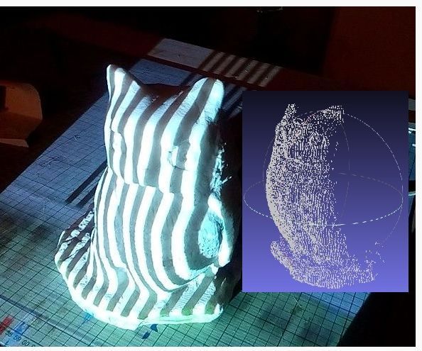 If this information is not properly processed directly in the process of its transfer from the contractor to the customer, then it may be distorted or lost forever.
Speaking of a “data collection” tool, it is essential to find one that allows you to organize data in order to enable you to make optimal management decisions. It is this approach that allows navigation with a high degree of accuracy, while displaying real connections between design positions, as a result forming an intelligent model of the operating object.
The implementation of the laser scanning technology described above, the creation of a point cloud and a geometric and subsequently information model, allows you to fully familiarize yourself with the features of solving the problem of restoring the information model of an existing object.
You should refer to an example project illustrating the application of the technology described above. In 2013, a team of specialists, which included representatives of companies Intergraph (Intergraph PP&M Russia), Trimetari (St.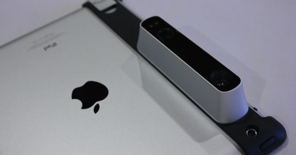 Petersburg), Navgeocom (Moscow), implemented a project to obtain a three-dimensional information model of an engineering facility (reserve diesel power plant of the 3rd power unit of the Rostov NPP) based on laser scanning technologies. The Customer was the leading design institute in the structure of the State Corporation Rosatom - United Company OJSC NIAEP - CJSC Atomstroyexport. The main goal of the work is to test the effectiveness of laser scanning and Intergraph technologies as a method of building an "as built" model when reconstructing existing objects, when designing new objects based on existing ones in order to replicate the design solution, at the operational stage, etc. It should be noted that the authors cases of similar projects being carried out in Russia are unknown, although foreign design and operating organizations have long and successfully used the capabilities of laser scanning and Intergraph CAD to perform these tasks.
The object was Rostov NPP , one of the largest energy enterprises in the south of Russia.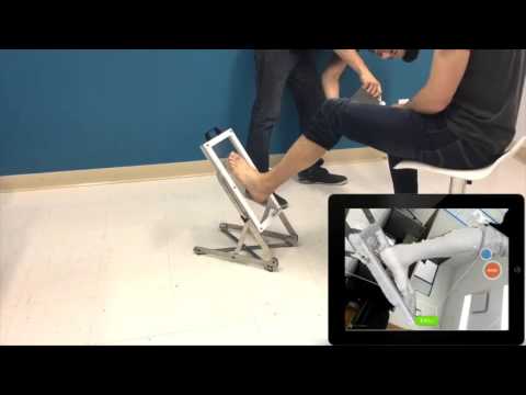 Power unit No. 1 is at the stage of pilot operation at a capacity level of 104% of the design one, power unit No. 2 was put into operation in 2010. Power units No. 3 and No. 4 are currently under construction, the launch of which was scheduled for 2014 and 2017. Electricity generation is over 25 million kWh per day and about 8 billion kWh per year.
Laser scanning work was carried out at the reserve diesel power plant of power unit No. 3. This facility has 3 levels located at elevations from −7 m to +9.6 m.
When planning work, the following list of stages was approved:
- analysis of the received project documentation from NIAEP specialists,
- field work on site - laser scanning ,
- primary processing of laser scanning field data - registration and georeferencing of scans,
- creating a service of spherical panoramas,
- building a geometric (non-intelligent) model,
- obtaining intelligent three-dimensional model of the operating object
- preparation of a server grouping for a project:
- provisioning servers,
- software deployment and configuration,
- preparation of catalogs for simulation:
- unfolding the received project catalogs for further use at the 3D modeling stage,
- directly 3D modeling 3rd cell of the RDES building,
- comparison of simulation results with an available geometry model,
- processing of the submitted documentation set, structuring and loading data into the Intergraph SmartPlant Fusion system,
- Creation of a unified integration platform based on the Intergraph SmartPlant Foundation.

To perform field work on laser scanning, the scanner ScanStation P20 was used - the latest model of the Swiss manufacturer of geodetic equipment Leica Geosystems . The device has excellent technical characteristics for shooting complex industrial structures - a maximum range of 120 m at 18% reflectivity, a distance accuracy of less than 1 mm, a speed of up to 1 million points per second, a built-in camera. In addition, the possibility of continuing the project with the shooting of the object from the outside in the cold season caused special requirements for the “endurance” of the scanning system. The parameters of the P20 scanner - operating temperature from -20°С to +50°С and dust and moisture protection IP54 - allow the device to be used in harsh climatic conditions.
Initially, a work plan for scanning of was developed at the facility, a registration method was chosen, and scanner installation locations were determined.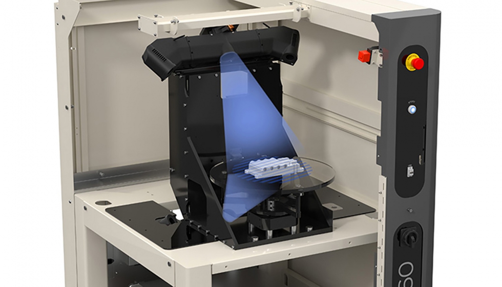 Direct laser scanning was carried out in 360-degree mode with panoramic photography of the object. Over two days of field work, surveys were made from 38 stations. Scanning was complicated by the ongoing construction and installation work at the facility. Advantages of the method - non-contact and speed surveys - allow you to minimize the impact of laser scanning work on construction or operational processes at industrial facilities.
All subsequent work was carried out in camera, remotely from the object. The initial processing of laser scanning data - registration of scans (combining into a single coordinate system) was completed in one day. The registration result - point cloud - is a virtual copy of a real object with millimeter detail (see Figure 8). The total number of points in the final cloud was 1.3 billion.
Geometric modeling of was performed in the Leica Cyclone software. It took 23 man-days to create a vector model from a point cloud.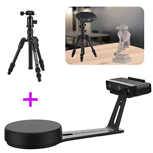 Despite the fact that the Leica Cyclone has ample opportunities for automatically fitting graphic primitives into a point cloud, modeling work is mostly manual and very painstaking work.
To download point clouds and their subsequent processing in Smart3D, the following software was used:
- Leica Cyclone;
- Leica CloudWorx for Smart3D;
The file was loaded into the same working project on which the object was built, which made it possible to combine the design model and the actual data (as built). Next, the object was divided into sections according to the alignment construction axes, after which we analyzed these sections for compliance - with the identification and recording of discrepancies. Thus, as a result of the work done, we received a list of actual discrepancies, supported by visual materials. This made it possible to quickly eliminate the discrepancies found even at the construction stage and significantly improve the quality of the final object, ultimately achieving its full compliance with the working documentation.
It is difficult to underestimate the opportunities that open up:
- automatic point cloud model building
- automatic detection of model intersections with a point cloud, for example, if the model was built without taking into account the location of the object's point cloud.
- building a new (non-existent) structure without building the rest of the model.
Using Cyclone or CloudWorx you can organize group data processing. Cyclone works as a client-server application, so you can create simultaneous access from multiple computers to one database. At the same time, all changes made on one computer will be immediately visible on others. This property significantly speeds up the processing of large data arrays.
Remote and mobile access to ensure a complete work is carried out using the SPF Web portal or the Dashboard.
The obtained three-dimensional model of the object and high-resolution panoramic images obtained as a result of laser scanning were published in the SmartPlant Foundation, a portal integration core of integrated design, an information flow management solution from Intergraph.
In addition, as part of the work on the pilot project, JSC NIAEP specialists transferred about 600 MB of unstructured documentation for 7 sections of the project in various formats. Most of the submitted documentation was in scanned form. With the help of the ABBYY software product, the scanned documentation was processed, and the xml files with smart data and source documents were loaded into SmartPlant Fusion. Documentation in dwg, doc, xls, etc. format was processed using the built-in SmartPlant Fusion tools, and no preliminary recognition was required using ABBYY. In SmartPlant Fusion, the downloaded documentation was automatically, according to pre-configured rules, structured by project sections. The classification of project items according to the relevant standard was also set up.
SmartPlant Fusion "can" process various sources of information, extract data in accordance with the configured rules, and, based on this data, restore a consolidated information model.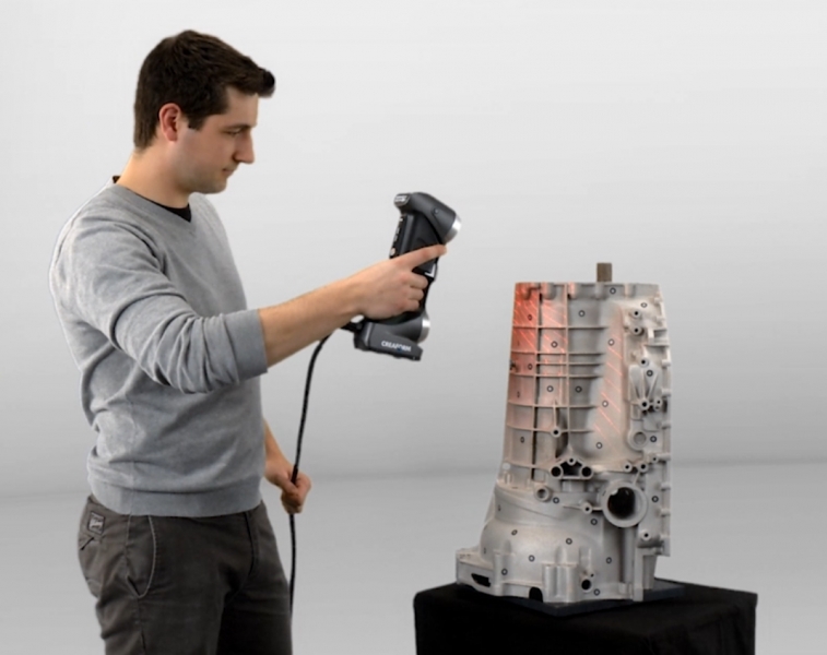 The project used various approaches to obtain data. Information can be obtained from the stamp of the document itself (for example, the document type and description from the document stamp), from the file name (for example, in this project it was the archive number of the document), from the folder structure of the transferred documentation set (in the project, based on the folder structure were classified documents). The system allows you to extract information on equipment and related documentation, build relationships and navigate between these objects. For example, by selecting the desired design position (pump, valve, etc.), you can view all documents in the system related to it, for example, a process flow diagram, wiring diagram, specifications, etc. The navigation mechanism allows you to switch from a design position to a photorealistic panoramic image obtained as a result of laser scanning and loaded into the system, and see how this equipment is mounted on the site. This functionality will help to compare the actual state of the object with the way it is displayed in the engineering documentation.
 Remote and mobile access to ensure a complete work is carried out using the SPF Web portal or the Dashboard.
When demonstrating the results of the pilot project to the specialists of JSC NIAEP - CJSC Atomstroyexport, as well as representatives of other organizations, the demand for laser scanning technologies and the SmartPlant Fusion solution was noted:
- in the reconstruction of existing facilities,
- when designing new facilities based on existing ones in order to replicate the design solution,
- in commissioning,
- in service,
- for decommissioning,
- for the purpose of extending the life of the operating object,
- for monitoring construction and installation works,
- to control the supply of equipment.
Gerhard Sallinger, President of Intergraph Process, Power & Marine:
"The completed project illustrates the high potential of carrying out work of this kind at other industrial facilities. "NIAEP-ASE recognizes the effectiveness of using Intergraph solutions for information management. This ensures safety in operating conditions and reduce the cost of the project. We are very proud of the results achieved together."
About authors:
- Mikhail Anikushkin, General Director of Trimetari LLC, St. Petersburg,
- Evgeniy Beletsky, Head of Technical Support Department, Intergraph PPendM LLC,
- Okounkova Evgenia, Project Manager, Intergraph PPendM LLC,
- Svyatoslav Serkov, Product Manager Laser Scanners, Navgeocom LLC, Moscow.
- Sergey Smirnov, Lead Engineer, Intergraph
The X-Ray Era: X-ray Wood Scanners
Modern log scanning technology can significantly increase productivity and reduce waste in the sawmill industry. One of the newest trends in this segment of equipment is X-ray scanners. Let's leave aside aspects of logistics and pricing policy, which in the current situation raise a lot of questions, and focus on the technological features of these systems.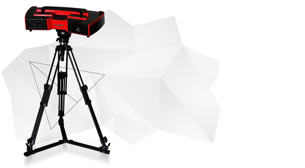
Fluoroscopy is based on the property of x-rays to weaken depending on the density of the material being examined. The density of defects is higher or lower than the density of the base wood, so they are quite easy to detect in the images obtained during the scan - they are indicated as darker or lighter areas.
X-ray scanner allows you to see what is not available to standard 3D scanners - the internal structure of a log: wood density, annual rings, heartwood content, knots, rot, mineral and metal inclusions and other defects.
In addition, X-ray scanning is a faster process and less influenced by external factors. Thanks to this, such equipment brings scanning of timber products to a whole new level of quality and accuracy.
A new level of accuracy
“3D scanning is the measurement of the outer geometry of timber or lumber. This method is based on laser triangulation. X-ray scanning is a measurement of timber using ionizing radiation, and the main characteristic on which the whole process is based is the density of wood and its distribution inside the log.

Based on the density distribution and its difference between the inner layers of the log, such as bark, bast, knots, core, the size of the wood without bark is determined with high accuracy, but the bark itself remains on the log, ”explains the director of Finnos LLC Rus” Andrey Savostyanov.
According to a representative of a manufacturing company, the accuracy of measuring the diameter of a log under the bark of X-ray scanning systems is almost no longer superior to modern 3D scanners - this figure averages + -1 mm.
“But at the same time, the work of X-ray equipment is not affected by dirt on the surface of the log, icing and other factors that greatly affect the measurement of external geometry and underestimate its accuracy in the case of 3D scanners.
When using X-ray scanners, the measurement takes place only by the density of wood, and the result of getting the diameter into its variety group reaches 98%. On 3D systems - a maximum of 85% due to the above factors, ”comments Andrey Savostyanov.

“The fundamental difference between X-ray log scanners is that X-ray allows you to “look” inside the log, to see its internal structure and wood defects. As for the result, in contrast to the classic 3D-scanning, which uses the so-called coefficients per bark, the X-ray scanner measures the actual diameter of the log under the bark.
Therefore, when sorting sawlogs using X-rays, the yield of sawn timber increases by 1.5–2.5%, depending on the sawmill equipment used, sorting scheme and other characteristics,” Sergey Kirilin, director of Finscan Rus LLC, gives his assessment.
What are we looking for and where?
As already mentioned, the main principle of operation of X-ray scanners is to measure the density of the material under study. Therefore, X-rays allow you to see defects that differ in density from the main mass of wood: knots, soft rot, mineral inclusions. Also, this equipment can detect complex log curvature, bark tears and other defects related to both geometry and the internal structure of wood.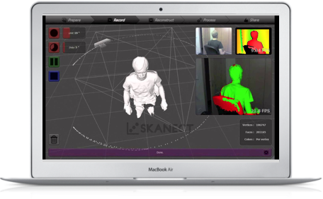
“The main area of application for X-ray scanning systems for round timber is, of course, sawmilling, where it is necessary to accurately measure the diameter of logs, sort them and accurately fit the log into the log. At this stage, all the defects of the wood are hidden, therefore, X-ray scanning is optimal for the high-quality performance of all stages.
But this system is also relevant for plywood production. With the help of an X-ray scanner, we can sort the fankrya according to the bucking pattern, formats, and internal defects. This significantly increases the efficiency of raw material use, reduces the cost of its preparation and ensures economic efficiency already at the stage of sorting fankrya.
Our company also has a development for measuring the volume of wood chips and its moisture content using an X-ray scanner,” the director of Finnos Rus LLC shared his vision.
“In my opinion, first of all, X-ray scanners should be used when sorting roundwood, where this equipment will bring the greatest efficiency.
Also, X-ray scanners will be useful when receiving wood chips at the pulp and paper mill, allowing you to measure the actual volume of chips and find mineral inclusions that are not allowed in production.
In addition, some mills for sorting planed products order longitudinal scanners with an X-ray module, which in this case is used to assess the strength of the products.
The use of X-rays for cross-grading of non-planed sawn timber is impractical, because due to the relatively small thickness of the boards, they practically do not contain internal defects that do not appear on the face, and ordinary 3D scanners do an excellent job with visible defects, ”emphasizes the director of Finscan Rus ".
Two in one
Is it possible to combine X-ray with laser or 3D scanning in one scanner? And do modern timber merchants need such complex technological solutions? After all, to work with such equipment, highly qualified personnel will be required, and its maintenance will not be easy.
Today there are indeed solutions that combine all these measurement methods. They allow you to get the most accurate 3D models of logs in terms of external geometry and internal structure. For example, such equipment is supplied to the Russian market by Finnos Rus.
“This works almost like a CT scanner, but much cheaper. For the operator, there is absolutely no difference which system module is on the line - only X-ray, only 3D, or the flagship that combines all measurement technologies.
The interface is intuitive, the entire line is controlled automatically, the operator only monitors the supply of raw materials and enters the initial data into the system. The operator does not perform any fine-tuning or maintenance of the equipment, except for filling the washer fluid, this is done by a trained service team, ”explains Andrey Savostyanov.
Such a complex system is certainly more complex and expensive equipment than just stereo cameras in 3D systems. In addition, this technique is assigned a certain class of danger to human life, which is why the security systems there are much more expensive than in 3D systems.
“The use of X-ray scanners in these areas instead of classic 3D systems is now a growing trend. It won't be long before X-rays for sorting logs will become as commonplace for medium and large mills as the use of 3D scanners is today. But, of course, both 2D / 3D and laser scanners will have their own areas of application - for example, bar scanners on sawmill lines, wane scanners, etc., ”Sergey Kirilin makes forecasts.
Scanning at the root
It is possible to detect wood defects not only in a felled tree, but also in a growing one. Previously, the diagnosis of the condition inside the trunk was performed using a needle, which, penetrating into the plant, measured the degree of resistance of the material, or they used a technology based on measuring the speed of propagation of sound pulses through the wood. Such equipment is quite expensive, and an experienced
operator is required to work with it.
Specialists from the Arctic State Agrotechnological University (Yakutsk), together with colleagues from the Zyfra Center for Industrial Radiography, proposed a different solution based on X-rays. With the help of a portable instrument complex developed by them, taking a picture of a living tree is no more difficult than taking a “stick” for a living person.
The principle is the same: an X-ray source is installed on one side of the barrel, and a receiver on the other. It takes only a few seconds to take a picture. The weight of the equipment is only 10 kg, it does not need to be adjusted, so one person can easily cope with this work.
“When using equipment that works on other principles, it takes about half an hour to diagnose one tree. With the help of our complex, this time is reduced to five minutes, ”Igor Grigoriev, professor of the Department of Technology and Equipment of the Forestry Complex, at the Arctic State Agrotechnological University, commented to Izvestia.
With this device, rot, knots, cracks, foreign matter, insect damage from 1 mm in size and other damage inside the trunk of growing trees can be detected using X-rays, without compromising their integrity. In a word, the principles are the same as when scanning felled wood.
True, it is planned to use the development primarily not in industry, but in forestry - to monitor the condition of trees in forests and forest park areas in order to identify plants that, due to internal damage, can suddenly fall and damage surrounding trees or buildings. Another possible area of application is monitoring the condition of wooden structures.
So, according to Igor Shkradyuk, expert of the Public Council under the Ministry of Natural Resources, coordinator of the program for greening industry at the Center for Wildlife Conservation, the problem of the condition of trees is most acute in cities where unstable trunks falling from the wind can cause significant damage and even lead to death of residents .