Abaqus 3d printing simulation
Additive Manufacturing Simulations in Abaqus
Abaqus version 2022 now offers fully embedded additive manufacturing (AM) process simulation features. The AM Modeler plug-in, which previously had to be downloaded from the Dassault Systèmes website, is now available as a built-in plug-in in Abaqus/CAE.
New features for this kind of simulation are still being developed and added to Abaqus. The current release (2022) also brought a pattern-based method for thermomechanical analyses of powder-bead type AM processes and modeling of metallurgical phase transformations.
What is more, the first fix pack for Abaqus 2022 introduced the ability to vary both the bead width and bead orientation in Fused Deposition Modeling (FDM) and Laser Directed Energy Deposition (LDED) processes.
The AM Modeler plug-in was refactored a few times in previous years. Currently, its new model creation window has the following appearance:
The available analysis types include:
- Eigenstrain
-
- Trajectory-based
-
- Pattern-based
- Thermo-mechanical
-
- Powder-bed
-
-
- Trajectory-based
- Pattern-based
-
- LDED
- FDM
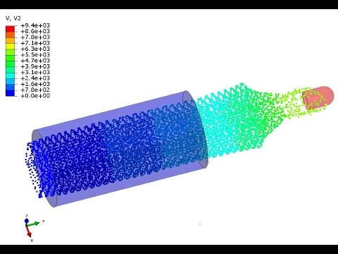
Eigenstrain-based simulations consist of just a single stress analysis with a predefined set of eigenstrains applied to each element upon activation and representing the inelastic deformations occurring during the additive manufacturing process. Eigenstrains are understood as all sources of inelastic deformations leading to residual stresses and distortions of products. Thermal strains are among them. These simulations can be either trajectory-based or pattern-based. In the first case, element activation and application of eigenstrains are based on a specified trajectory of material addition. In the second case, elements are activated layer by layer and eigenstrains are applied based on a specified in-plane pattern for each layer.
Thermo-mechanical simulations are a standard approach involving sequential thermal-stress analyses consisting of a transient heat transfer step followed by a static step that uses the temperatures from the first stage as loads. In the case of powder-bed type processes, simulations can be carried out using the traditional trajectory-based approach or the new pattern-based approach. The first method requires the specification of laser and recoater/roller blade paths in the format used by event series - time, coordinates and value (laser power or recoater state - on or off).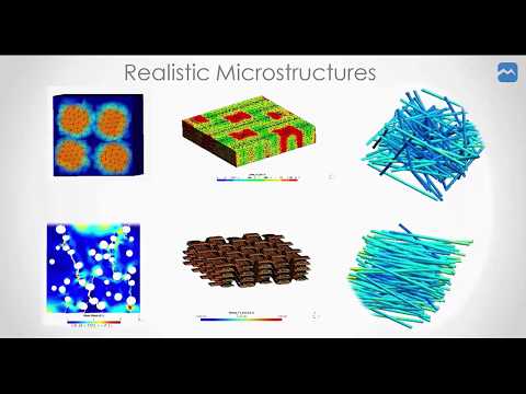 Instead of describing toolpath trajectories, the second method involves the definition of a scan pattern representing the idealized motion of a tool. The part is divided into slices perpendicular to the printing direction. Those are further divided into rectangular unit cells consisting of several patches with local orientations of the scanning motion with respect to one of the build axes.
Modeling of metallurgical phase transformations is another new feature meant for simulations of additive manufacturing processes, it can also be used for analyses of other forms of heat treatment. A special-purpose built-in user-defined material is available for this purpose and can be accessed by using material names and parameter/property table types starting with "ABQ_PHASE_TRANS". This framework can account for the melting and solidification of raw material, as well as for the subsequent metallurgical solid-state phase transformations caused by heating and cooling. It’s also possible to account for the size and morphology of grains.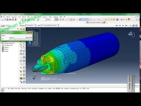 The concept of the Raw-Liquid-Solid (RLS) state of the material is used. The fused material can be remelted during the analysis. Transitions between these three states occur within temperature ranges bounded by solidus and liquidus temperatures. Apart from that, two types of solid-state transformations are supported - diffusional and martensitic. The kinetics of these transformations are defined by using time-temperature-transformation (TTT) diagrams or by specifying proper coefficients directly. It is also possible to specify material properties as functions of a metallurgical state.
The plot obtained from a single-element benchmark problem from Abaqus documentation is shown below. The analysis was performed for a titanium alloy Ti-6Al-4V subjected to temperature cycles with constant heating and cooling rates.
The changes in phase content are depicted in this plot. Phases beta, alpha and alpha prime are commonly known in metallurgy when titanium is considered. The RLS variable describes the material as raw (-1), liquid (0) or solid (1).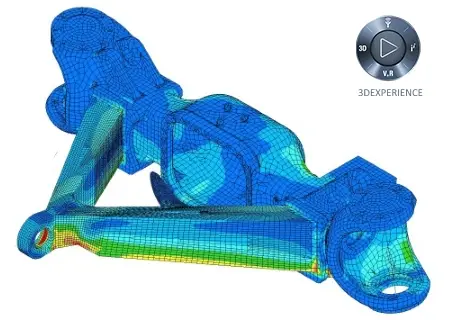 It can be seen that the beta phase initially dominates when the material is in a solid state. Then, the martensitic transformation occurs and the beta phase changes to alpha prime.
The diagram below shows the temperature cycles applied in this model:
-
Abaqus 2022 introduced a pattern-based method for thermomechanical analyses of powder-bead type AM processes and modeling of metallurgical phase transformations.
-
The first fix pack for Abaqus 2022 added the ability to vary both the bead width and bead orientation in AM process simulations.

-
Built-in AM analysis types include both eigenstrain and thermomechanical simulations with either trajectory-based or pattern-based approach (for selected AM processes).
-
AM features in Abaqus cover powder-bed, LDED and FDM manufacturing methods.
 Other processes could be simulated with more manual approach.
-
Metallurgical phase transformation modeling framework accounts for melting and solidification but also solid-state phase transitions in metals.
-
The Abaqus functionalities discussed above allow for realistic simulations of a wide range of additive manufacturing processes.
Additive Manufacturing or 3D Printing simulation in ABAQUS
Additive Manufacturing or 3D Printing simulation in ABAQUS
3D printing or additive manufacturing simulation is the process of producing 3D parts of a digital file. This technology is important because computer-aided design and 3D printing directly lead to the production of physical components. The process of 3D printing of an object is created by placing successive layers of materials, and this process continues until the part is completed.
Two methods
This educational package includes two 3D printing modeling methods. The first method is based on the use of subroutines and Python scripting and was done by a team with the goal of coding all the steps of 3D printing. In the second method, the ADM plug-in is used to simulation of additive manufacturing. This plugin is an advanced tool to simulate 3d printing process and cover different ADM processes. It seems the best tool to do simulate additive manufacturing or 3d printing up to Now!
Method 1: Using Scripting and Subroutines
In this method, several assumptions have been applied in each version of these codes. In this method, scripting is used to carry out all simulation steps until the implementation of the solution, and even the input of the problem is done by the graphical environment created by the script.
For the workshops of this method, in version 1.0.0, a 3D printing of gear and an industrial shaft has been used.
In this method, after defining the printed geometry and the required mechanical specifications and the 3D printer details, first, in a lesson, the theories governing 3D printing in this method, including the formulation, are fully presented. After the flowchart, the written script and subroutine are described line by line. In this workshop, the gear is printed along the Y axis. The important point in this workshop is that since the piece has the same sections along the Z direction, one layer is introduced to the script, and other layers are created from it. The subroutines used in this workshop are DISP and USDFLD subroutines.
In the second workshop, an industrial shaft is printed. This shaft has different sections. So, scripts and subroutines are different from the first workshop. Also, printing in this workshop is done on the Z axis. The subroutines used in this workshop are DISP and USDFLD same as the previous workshop.
Method 2: Using ADM plugin
This method, which is the most advanced and accurate method of simulating 3D printing, has been tried to give engineers the necessary facilities by using different techniques so that they can create the simulation with the closest conditions to the real model. In this method, the types of 3D printing methods and their applications are fully and comprehensively explained. After that, the method of using plugins will be explained by introducing the options and tools of this plugin. So, by solving numerous examples with all kinds of 3D printing simulation methods for different parts, it is tried to provide complete mastery for the engineers, factories and researchers so that they can provide simulation for their models with the best possible speed and accuracy.
This method will be available soon after purchase on your dashboard.
Design and manufacture of ceramic bone implants of complex shape using 3D printing based on stereolithography
The Skoltech Center for Design, Manufacturing Technologies and Materials (CDMM) has developed a new effective method for designing and manufacturing biomedical implants as part of a multidisciplinary approach. The results of the study are published in the journal Applied Sciences .
Complexly shaped biomedical implants designed to replace bone defects are often made of ceramic materials to provide the necessary strength to the damaged area of the bone, reduce inflammation, and stimulate the growth of living cells and osteogenesis.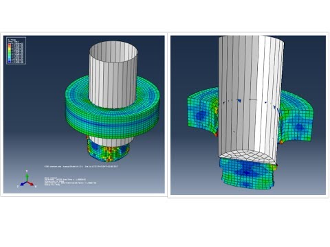 It is assumed that living cells should penetrate into the internal space of the implant, gain a foothold on its surface and promote the development of the process of tissue regeneration. To do this, the implant must have a porous structure, and the pore size must be from several tens to several hundreds of micrometers. In this case, porosity should be provided throughout the entire volume of the implant. Unlike traditional manufacturing technologies, where it is difficult to control the size and geometry of the pores, additive manufacturing technologies allow you to vary the size and geometric parameters of each individual pore to ensure their exact match to the microstructure of the bone tissue in the implant area and optimize the cell regeneration process.
A complex multidisciplinary study was carried out at Skoltech, bringing together the best practices of three CDMM research groups working in different directions. The overall concept and design of the implants was developed by the Additive Ceramics Manufacturing team of Dr. Svyatoslav Chugunov and Andrey Tikhonov based on the technical requirements provided by the partner medical organization. Already at the stage of preliminary design of implants using conventional CAD models, the shortcomings of this traditional modeling method, which does not take into account changes in pore parameters, support thickness and morphology of joints between the main elements of the implant, became apparent. The traditional CAD method allows one to build several static models of the device, but does not make it possible to easily change its mesh topology and obtain the desired implant structure individually for each patient.
A second group of Skoltech researchers, Prof. Alexander Pasko, Dr. Evgeny Maltsev, and graduate student Dmitry Popov, modeled implants using the functional representation-based (FRep) method, which provides greater flexibility in geometry selection and allows control over the parameters of each element porous structure. The FRep method describes the geometry of an object using mathematical functions. For example, an ordinary cup can be described by mathematical equations that replace the main constituent elements of an object - a sphere, a cube, a cylinder, etc. Morphological and topological operations with an object (rotation, displacement, union, division, intersection of elements, etc.) are performed in the form of mathematical operations with equations describing these elements. By combining and building all the equations and operations in a certain order, you can get a sequence of mathematical formulas that describe geometric objects of a very complex shape (Fig. 1). The programmatic representation of such a sequence consists of only a few lines of code. With the help of additional operations, such as looping, zone copying and transfer, it is possible to automate the generation of periodic structures for very large objects without significantly increasing the length of the program code. The FRep method is a combination of various geometric modeling methods
- from the use of implicit surfaces and the method of constructive solid geometry to procedural 3D modeling.
Figure 1. Example of operations used in the FRep method.
Entering parameters into equations and mathematical operators is possible at any level of modeling by the FRep method, which allows you to correct any part of the geometry of an object at any stage of modeling. Equations describing the basic constituent elements of an object can refer to both the geometry of the object and the material from which it is made. By applying mathematical operations to equations related to materials, it is possible to create heterogeneous objects, including those with a density gradient. This process can also be effectively parameterized, which allows you to make changes to periodic structures on the fly and modify any element of the structure in order to add separate new functions (Fig. 2).
Figure 2. Examples of geometric objects created using the FRep method.
A geometric object created using the FRep method can be exported to files of various formats, including STL. STL files can be used in any slicing software to prepare a model for 3D printing.
The main advantages of the FRep method compared to classical CAD modeling are the wide possibilities for parameterization of each modeled object, a convenient form of representing complex geometric shapes in the form of several lines of program code, and the ability to develop computer or mobile applications that allow you to create geometrically complex objects, adjust the topology and morphology of the geometry with one movement of the slider in the graphical interface and export the result to an STL file ready for 3D printing (Fig. 3). Creating an application for 4-5 parametric models using the FRep method is a simple task that takes only 1-2 days to complete. With a ready-made application with a graphical interface, further operations for designing implants and customizing their structure to specific scenarios can be performed even by users who do not have experience with CAD and 3D printing systems. The exported STL file requires minimal setup for a specific 3D printer.
Figure 3. Graphical user interface for the bioimplant simulation software.
Bone implants must be strong enough to withstand the same mechanical loads as bone tissue, as well as loads from external objects in contact with them. Ensuring the mechanical strength of implants is of great importance. The third group of Skoltech researchers led by Professor Alexander Safonov from the CDMM Composite Materials Laboratory performed numerical simulations of the mechanical properties and failure scenarios of the implant material using the ABAQUS finite element software package. According to the specialists of the partner medical organization, compressive loading is the most typical for this type of implants. The researchers performed compressive strength calculations for STL models created using the FRep method using the ABAQUS complex, and also identified potential areas of failure. The discrepancy between the results of numerical simulation and experimental data was no more than 5%.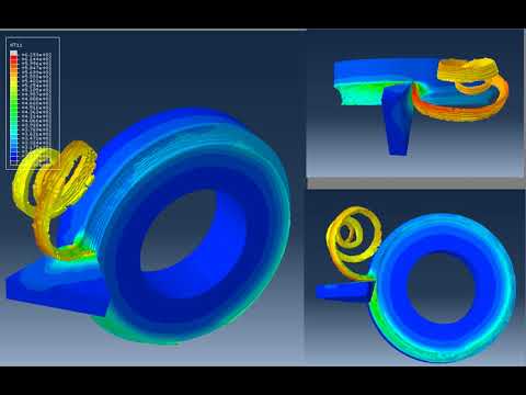
Based on the simulation results, the researchers of the Additive Manufacturing Laboratory produced four samples of implants of different designs and tested them in the CDMM Mechanical Testing Laboratory with the participation of laboratory engineer Stepan Konev. The tests used a Digital Image Correlation (DIC) system that evaluated the performance of implants under load over time. The use of data on strain fields obtained using DIC made it possible to evaluate the contribution of each component of the network structure to the mechanical characteristics of the sample and to determine the moment in time when the destruction of the material occurs. It was noted that the results of numerical simulation are in good agreement with the experimental data on the destruction of materials. All tested implants met the specified requirements. Using 3D printing, a series of implant samples were made for medical analysis.
The results of the study confirm the effectiveness of the FRep method not only for creating complex geometric structures, but also for developing applications with a convenient graphical interface that allows you to quickly create many implant models with the ability to change the parameters of any of the elements.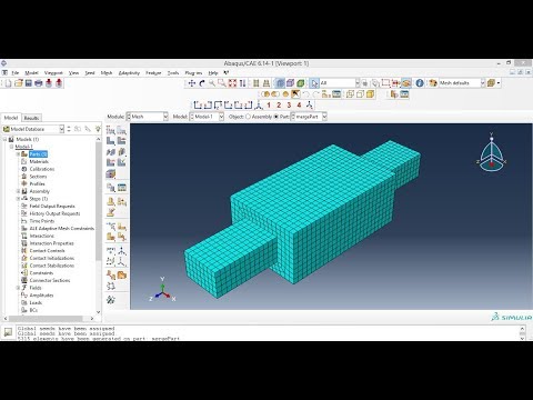 The combination of the FRep modeling method, numerical analysis based on the finite element method and additive manufacturing technologies makes it possible to obtain custom-made biomedical implants at relatively low cost and in the shortest possible time (about 10 days). Additive manufacturing has a number of additional advantages: it allows you to create products of complex shape and, no less important, to produce dozens and even hundreds of customized implants on a single printing platform within a single production run.
The engineering approach demonstrated in this work can be put into practice as a pilot application for the rapid production of biomedical implants that meet medical requirements and take into account the individual characteristics of patients. The researchers plan not only to expand the range of ceramic materials used, but also to develop a new method for 3D printing ceramic products with a porous structure, which will reduce the post-processing time of blanks and improve the quality of the internal structure of a 3D printed part.
Contacts:
SKOLTECH COMMUNICATIONS
+7 (495) 280 14 81
* Protected email *
* Protected Email
on the UAL. Additic technologies
of the news on the materials of the LIVONED MARIS UAC start producing parts with bionic design. Purely externally 3D printed parts look unlike most structural elements designed over the past decades. Over time, due to their lower weight and ease of release, they can noticeably replace parts created using traditional technologies.
Anton Leonov, Leading Technologist of the Materials Science Department, demonstrates an aluminum power bracket for a new fighter.
Bracket - completely domestic development. The designers of the Sukhoi company designed the part on a supercomputer. Specialists of the All-Russian Scientific Research Institute of Aviation Materials (VIAM) printed a part on a 3D printer from a domestic aluminum alloy metal-powder composition created on its basis. The design is more reminiscent of a bone of some prehistoric animal than a fifth-generation fighter part. A number of technological features of the new part indicate that the development is unlikely to have to gather dust somewhere on a museum shelf for a long time. The new bracket is a quarter lighter than its predecessors, which are currently flown by current machines today and are made using traditional technologies. “The whole process, from designing a part from scratch to adapting the technology and putting it into production, took a little over a year,” says Andrey Filatov, head of the research department of materials and technologies at the Sukhoi Design Bureau. And another important nuance. The part, almost half a meter long, was made by laser sintering in just one night.
Traditional machining of an aluminum billet would take at least a week. Thanks to the use of 3D printing in the part, it was possible to create cavities that cannot be “gnawed through” on a conventional CNC machine when processing the part.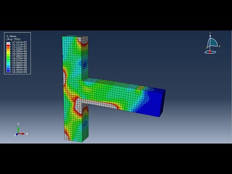 In search of the perfect shape. About ten years ago, Alexander Rozhkin and Valentin Martynov completed their studies at the Department of Strength at the Moscow Aviation Institute (MAI). Their study, among other things, was connected with the use of supercomputers. Valentin shows an extensive presentation of the details developed at Sukhoi using the so-called “hybrid design”, when, when creating a new design, the optimal location of numerous power elements is determined based on a mathematical model by topological optimization methods and is further interpreted into a construct taking into account the capabilities of technologies and even design. The first detail is a wind turbine bracket for the Sukhoi Superjet 100 passenger liner, the designers created back in 2008. The use of numerical synthesis of structural power schemes made it possible to design the part in such a way that, with the same weight, its rigidity became five times higher compared to traditional design methods.
According to Alexander Rozhkin, the hybrid design method has been extended to many new and existing products. The designers have created several drawings of details, such as elements of the tail unit, load-bearing structures. “Traditional formulas for the strength of materials and structural mechanics could make it possible to calculate more simplified structures by analytical methods, even on a calculator. If we used the classical methods of strength calculation, we would have to do a volume of work comparable in volume to a good dissertation. Without numerical methods, coupled with a supercomputer and the use of new programs, the development of such details would be simply impossible, ”says Alexander. Hybrid, also known as generative, or bionic.
Parts made using stereolithography technology.
Generative design is a method of designing various objects that uses solutions other than traditional solutions to reduce weight and increase strength. Externally, objects produced in this way differ from ordinary man-made products. They have pronounced features inherent, for example, in plants, imitate the structure of limbs or bones.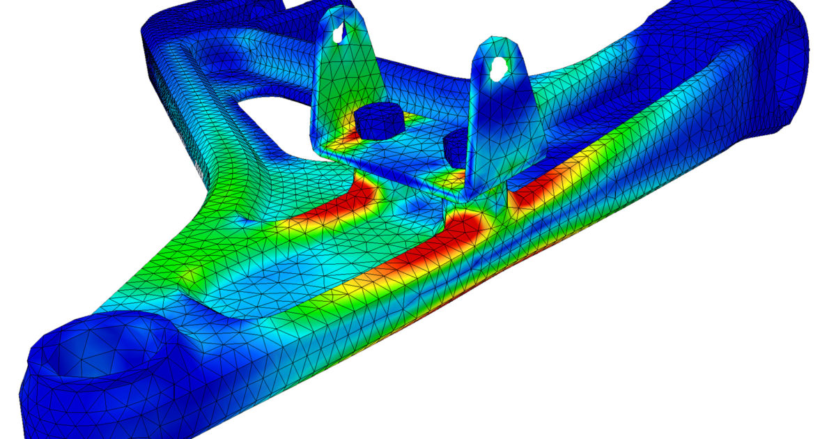 That is why this design method is often called bionic design. The term "generative design" is used due to the fact that the geometry of such structures is automatically calculated, as if generated in special software. This can be represented as a person who delegates part of the tasks to computer technology. The main task of bionic design is quite logical - reducing the weight of an object while maintaining or even increasing its original strength. That is why such solutions are more often used in areas where it is important to save every gram, including in the aircraft industry. Another related challenge in generative design is saving expensive materials such as complex alloys or rare metals.
The bionic design approach allows for some technological processes to use 30 or even 50% less material. Naturally, this has a positive effect on the price of such products. Creating structures based on generative design in most cases is possible only with the help of additive technologies (that is, a 3D printer), which use the method of layer-by-layer creation of a physical object from a digital 3D model. The fact is that traditional production methods are not able to realize projects with a complex structure of non-standard elements that bionic design offers. With the help of 3D printing, it is possible to produce elements with any thickness, curvature, cavities, mesh and cellular structures. In addition, layered construction gives bionic objects even greater strength and resistance to stress.
Fuel system parts.
The first test 3D printing was done on a special printer here in Moscow using VIAM equipment from a special domestic aluminum powder for printing. Meanwhile, the Sukhoi Design Bureau itself has its own 3D laboratory, where dozens of different parts for aircraft are made using stereolithography. The parts made by this method are well known to the pilots of the fifth generation Su-57 fighters at various stages of the creation and commissioning of equipment. For example, as Aleksey Yaremenko, the head of the research department of the model complex (NIO MK), recalls, the Sukhoi Design Bureau was able to very quickly choose the optimal design for the aircraft control stick. The joystick has several control buttons.
After the comments made by the pilots about the convenience of the button layout, it was possible to quickly finalize the initial project (where the pilot's fingers did not always reach the buttons) and offer a more convenient option. Yaremenko says that every year about five new parts created by the hybrid design method are launched from scratch, about ten more are made in pilot batches. Layered synthesis is printed and then cast in metal, for example, an aircraft control pedal. The use of hybrid design methods allows you to quickly refine the design of any individual unit, such as a bracket, and put it into production. A lot of parts are made for purge models of new aircraft. Recently, the Sukhoi Design Bureau made a model of the Russian-Chinese wide-body aircraft being created, which the head of state presented to the Chinese counterpart. Part of the details of this model were made using additive technologies. Exit is
An experimental prototype of the door hinge bracket for MS-21
The use of digital technologies at all stages of design allows today in aviation to do what seemed impossible only yesterday: to create a strong, elegant part with a minimum mass in a working day, using the most advanced methods of calculation and optimization, and tomorrow to print it in the next room, the day after tomorrow - to test, a week later - to install on the plane. The engineers of the Irkut corporation took seriously the implementation of this fantastic idea. Here, a little over a year ago, they began to introduce topological optimization procedures into the design process. Galina Gvozdeva, Lead Design Engineer of the Strength Department, shows the first prototypes grown using additive technology.
“This is a prototype of a door hinge bracket for the new MS-21-300 airliner,” says Galina. - The detail, of course, is not “combat”. The work is in the nature of R&D. The main issue that we set ourselves today is to determine the range of parts, the manufacture of which is expedient with the involvement of additive manufacturing. The task is difficult, especially when it comes to civil engineering. The priority for us as aircraft developers is the expansion of design and technological capabilities in the design and manufacture of parts. Behind the words “implementation of additive technologies”, we primarily see the prospects for increasing the mass efficiency of parts by optimizing the shape for existing loads, of course, while ensuring the required level of reliability. ”
According to Galina Gvozdeva, the choice of a prototype for research was taken seriously at the Irkut Corporation - with the involvement of the director of the design bureau, the chief technologist and the deputy chief designer for strength. We settled on an assembly unit of a complex configuration of more than 28 parts, not related to the main power elements. The part does not work in flight, its operation is not related to the perception of external flight loads and loads from overpressure. The design and manufacture of the first sample took about two weeks, which is a long time by the standards of "additive philosophy". “We strived to do not quickly, but qualitatively. We showed the results of topological optimization to designers, worked out the power flows in the structure, and only after that we developed a compromise design that combines traditional design solutions with bionic design elements. 28 parts were replaced with one! Galina recalls.
When the 3D model is ready, it should be adapted for printing. And here you can’t do without special knowledge of “additives”. The designers of Irkut were rescued by a long-term cooperation with the Moscow State Technological University "STANKIN". As part of this collaboration, Galina Gvozdeva even defended her dissertation under the guidance of the leading scientist in the field, Tatyana Tarasova. By the way, this was one of the first dissertations on additive manufacturing in Russia. It turned out to be an effective scientific and industrial union of a developer of a real design and an educational institution with a research laboratory. The work aroused a lively interest among equipment manufacturers. The companies SLM Solution (Rusky Group) and Concept Laser joined.
As a result, several prototypes were made at a scale of 40% of the real size in various configurations from aluminum alloys, titanium and steel. The work became interested in the center of aviation science - the Central Aerohydrodynamic Institute. Professor N. E. Zhukovsky (TsAGI), where full-scale strength tests were carried out. Their results allowed us to boldly talk about the prospects for the development of this innovative direction.
To date, Irkut has formed a working group for the introduction of additive technologies consisting of strength engineers, designers and technologists, and established strong ties with partner organizations. Airbrake innovation. Another striking example of the application of mathematical modeling methods to the development of efficient composite structures is the work carried out by the Ilyushin company together with scientists from the Department of Chemistry from the INUMIT company at Moscow State University. M. V. Lomonosov. When designing the air brake of the Il-114-300 aircraft, the use of the topological optimization method made it possible to create a unique integral design. It is planned to be 10% lighter and 20% less labor intensive to produce than traditional composite and metal solutions. Until the end of the year, the development of scientists will be implemented at the Voronezh Aviation Plant in the form of "combat" units of the Il-114-300 aircraft. Future top optimizers.
Bionic design parts.
Sergey Ershov - student of the group 10-501С of the 101st department of the MAI. He is the author and one of the executors of the Future of Aviation project. The history of the project is the participation of talented youth in the Big Challenges project shift at the Sirius Research and Education Center in Sochi. At this event, Mayevites Sergey Ershov, Evgeny Podobin and Artem Samoilovsky, together with schoolchildren from different parts of Russia, implemented the Future of Aviation project organized by UAC and MAI. Students and schoolchildren made a drone with composite wings from scratch.
This drone is distinguished by its lightweight design, obtained through a topological optimization method that is promising in the aircraft industry. Since one of the main production tools in the hands of young designers was a 3D printer, they managed to use this as an advantage for the production of a lightweight fuselage structure. Most of all, the guys did not have enough time. However, they were able to find a reasonable balance between the timing and capabilities of the equipment and printed the motor mount, not only lightening its weight by 20% in relation to the structure that could be made from a composite material by classical methods, but also avoided the need to produce tooling for production.
The material for 3D printing was a thermoplastic with the addition of carbon fiber. For calculations, the topological optimization software module U-opti, developed on the basis of the Abaqus software package, and software modules of the university's own design were used. This combination allowed to reduce the time and at the same time simplified the procedure for mastering the module by the project participants. In the process of work, the participants not only optimized the geometric shape of the drone units, but also took into account the features of the technological preparation of subsequent production on 3D printers in a software package developed within the walls of the Moscow Aviation Institute.