3D printed vertical gpu mount
▷ vertical gpu mount 3d models 【 STLFinder 】
Vertical GPU mount
thingiverse
Allows you to mount a GPU vertical on a board with limited space. This design fits with all types of GPU cards (mine is a Radeon R9 390X). I've provide the skp file if you want to rework it with SketchUp. ... Whole PC wall mount project is available...
Vertical GPU mount
thingiverse
Mount your GPU vertically with this study mount!
No case modifications required, should fit most cases that utilize a PSU cover.
Designed to provide the least amount of airflow hindrance.
Note: Using this mount will virtually leave all other. ..
Vertical GPU Mount
thingiverse
Edited GPU mount by "GregTheGreatOne" for my computer case. Added some thicker corners if i need to add some screws to secure it. Aiming to use the added fin to secure in the card slot area. Will need to be customized further, this will be a first...
Vertical GPU Mount
thingiverse
Remix of NICKOPOL411 design. ...recreated to fit a 120mm fan mount and relocated the end mounting screws. ... 123D Design source file included.
Vertical GPU Mount Meshify C
thingiverse
This is a bracket designed to allow vertical GPU mounting in the Fractal Design Meshify C and Define C case.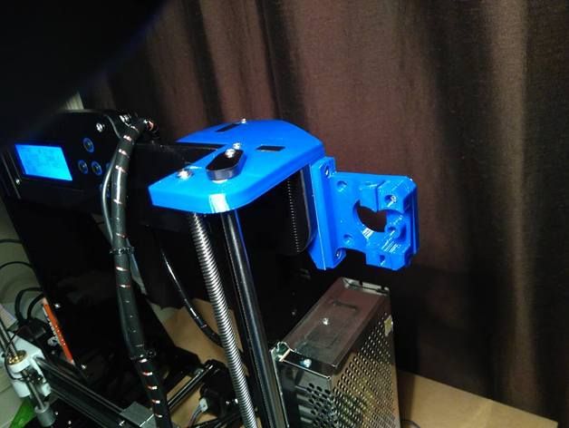 You will need to cut a hole in the hexagon mesh panel of the area next to the PCIe slots.
Slide the mount in from the outside and use fan...
You will need to cut a hole in the hexagon mesh panel of the area next to the PCIe slots.
Slide the mount in from the outside and use fan...
Vertical GPU Mount Ver. 2
thingiverse
This still does not require any modifications to the case BUT it now has the option for height adjustment to fit the GPU accordingly with those bulky cpu heatsink coolers. This also requires some screws to attach it inside the case, as well as...
Universal Vertical GPU Mount Amd Nvidia
pinshape
Universal 3d printed vertical GPU mount for Amd or Nvidia cards. Compatible with cases with 7 pcie slots and 2 slot cards. This is also compatible with the screws that come out of your PC slots so no special hardware needed. A riser card will be...
Corsair Air 540 Vertical GPU Mount
thingiverse
This is my design for a vertical GPU mount for the Corsair Air 540 case that will allow full use of other PCIe slots on the motherboard. The bracket where the IO plate attaches is universal for any dual slot bracket. It should fit any case...
Vertical GPU Mount Ver. 2 for Water Cooled
thingiverse
This is a remix of the original Vertical GPU Mount Ver. 2 by CrayonPhil.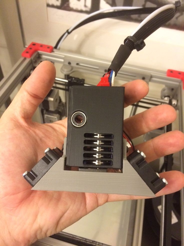 ...I extended the slider piece 1cm to fix a problem I had where my 120mm water cooling radiator got in the way of the GPU.
Vertical GPU Mount for Open PC Frame II (OPF-II)
thingiverse
These are the parts for a vertical GPU mount for the OPF-II. The remaining parts are posted under https://www.thingiverse.com/thing:4816054. All screwed together with 6/32 screws. I printed this in carbon fiber PETG. I made this for a EVGA 3090 FTW3...
SilentiumPC Armis AR7X Vertical GPU Mount Holder
thingiverse
The original holder almost caused a fire. Did this non conductive piece here.
... Hope it serves you well!
Did this non conductive piece here.
... Hope it serves you well!
GPU Vertical Mount - V1
thingiverse
#### [CHECK OUT THE NEW AND STRONGER VERSION 3](https://www.thingiverse.com/thing:3157988) #### Vertical GPU mount for 120 mm fan. I have strengthened the slot for the GPU and enlarged the holes to 5 mm diameter (mount + spacers). ... Spacers height...
GPU Vertical Mount - V3
thingiverse
### VERSION 3 ### * Stronger than VERSION 1 & 2 * Fits 120 mm fan drilling * Attaching the GPU: 3 holes with a diameter of 5 mm for threaded rods. * Attaching the mount: 4 holes with a diameter of 5 mm incl. ...50 mm high spacers
GPU Vertical Mount - V2
thingiverse
### VERSION 2 ### #### [CHECK OUT THE NEW AND STRONGER VERSION 3](https://www.thingiverse.com/thing:3157988) #### * Fits 120 mm fan drilling * Attaching the GPU: 2 holes for 6-32 UNC (threaded) screws. * Attaching the mount: 4 holes with a diameter...
GPU Vertical Mount - SLI
thingiverse
#### Intro A vertical GPU mount for SLI. I designed this mount in from scratch, using an old case to get the dimensions for the PCI slots and the alignment of the riser cables. I actually designed this in December 2017. I searched on Thingiverse for. ..
..
GPU Vertical Mount - PC Custom Case
thingiverse
I did print with supports on the GPU Mount file to keep the print clean, but the GPU Mount End file should print fine without them. I chose to break the design into two pieces to account for any variations in GPU faceplate designs. The two halves...
3-slot GPU Vertical Mount Adapter
thingiverse
... so the PCIe ribon doesn't have to go too far sideways. ... **DOES REQUIRE CASE MODIFICATION** and the three slots were slightly off in the original (required some force to get the GPU to drop into the adapter) My first submission to Thingiverse.
RVZ03 case gpu vertical mount 3x80mm
thingiverse
Silverstone RVZ03 case gpu verticalmount 3x80mm fans You have to drill holes or glue back panel to case and the back panel needs support You need this type of pci riser cable: Fractal Design Flex VRC
RVZ03 case gpu vertical mount 3x80mm
thingiverse
Silverstone RVZ03 case gpu verticalmount 3x80mm fans You have to drill holes or glue back panel to case and the back panel needs support You need this type of pci riser cable: Fractal Design Flex VRC
GPU VERTICAL
grabcad
Gpu vertical
GPU Vertical mount
thingiverse
flip the part 180 to print better
Vertical GPU mounting bracket
thingiverse
I recently completed a vertical gpu mounting mod on my youtube channel and wanted to upload the file to share! This was designed to fit in my phanteks enthoo pro m acrylic case but can be modified to fit others as well. ... Youtube video of the Vertical...
Vertical GPU mounting Bracket
thingiverse
New version of this make can be found here --> https://www.thingiverse.com/thing:3475590 This is a 3D printed Vertical GPU Mounting Bracket. This design does NOT require any modifications that would damage your case. This is only compatible...
Vertical GPU Mounting Bracket
thingiverse
Please note: I designed this specifically for the NZXT S340 Elite case and requires the cutting of some metal, as a result I have no idea if it would work for other cases (however as they're all mostly the same at the back, it should work fine -. ..
..
GPU Angled Vertical Mount for AC Kryographigs NEXT
thingiverse
Bracket to mount a GPU with a waterblock vertically with a slight angle. Designed for a 3080 with an Aquacomputer Kryographics Next waterblock, but it should fit other waterblocks too. ... Print 2 Designed to mount with 2 M5 Allen key, cylinder head...
Vertical Mount Gpu - Graphic Card
thingiverse
support for video card in vertical mode suporte para placa de video no modo vertical
Vertical GPU Support
thingiverse
A support for heavy vertically mounted GPU's that aren't quite straight.
vertical gpu bracket
thingiverse
Vertical gpu support for computer.
GPU mount *OUT DATED*
thingiverse
*OUT DATED AND WILL NOT FIT GPU'S WITHOUT MODDING IT.* GPU mount for vertical mounting gpu
GPU Vertical Brace
thingiverse
A Screw style GPU vertical brace. 8cm when fully closed. 12cm when reasonably extended but with room for a little more.
... Separated into 2 halves to prevent need for support filament.
▷ vertical gpu mount bracket 3d models 【 STLFinder 】
Vertical GPU mounting Bracket
thingiverse
New version of this make can be found here --> https://www.thingiverse.com/thing:3475590 This is a 3D printed Vertical GPU Mounting Bracket. This design does NOT require any modifications that would damage your case. This is only compatible...
Vertical GPU Mounting Bracket
thingiverse
Please note: I designed this specifically for the NZXT S340 Elite case and requires the cutting of some metal, as a result I have no idea if it would work for other cases (however as they're all mostly the same at the back, it should work fine -. ..
..
Vertical GPU mounting bracket
thingiverse
I recently completed a vertical gpu mounting mod on my youtube channel and wanted to upload the file to share! This was designed to fit in my phanteks enthoo pro m acrylic case but can be modified to fit others as well. ... Youtube video of the Vertical...
vertical gpu bracket
thingiverse
Vertical gpu support for computer.
GPU Vertical Bracket
thingiverse
. .. that it hid more than half the mainboard. It looked awful, wasn't stable enough and would have required to re-think my original tubing plan.
So i went ahead and designed my own Vertical GPU Bracket that fullfilled all my needs without compromise.
.. that it hid more than half the mainboard. It looked awful, wasn't stable enough and would have required to re-think my original tubing plan.
So i went ahead and designed my own Vertical GPU Bracket that fullfilled all my needs without compromise.
GPU Vertical Bracket
prusaprinters
Support me.Website: https://pixelglance.comBuy Models: https://cults3d.com/en/users/PixelGlance SummaryThis is Vertical Bracket for GPUs, and is perfectly fitted for the Lian-Li O11DXL-X PC Case.It offers way better stability than most purchaseable...
Vertical GPU mount
thingiverse
... I have a phanteks P350x case. I printed at 0.15mm layer height and 5% infill with 1mm outer/inner walls.
The included shim is for the lower mounting bracket of the gpu to allow you to space it frontwards or backwards in order to level your gpu.
I printed at 0.15mm layer height and 5% infill with 1mm outer/inner walls.
The included shim is for the lower mounting bracket of the gpu to allow you to space it frontwards or backwards in order to level your gpu.
GPU Vertical Mount - V1
thingiverse
#### [CHECK OUT THE NEW AND STRONGER VERSION 3](https://www.thingiverse.com/thing:3157988) #### Vertical GPU mount for 120 mm fan. I have strengthened the slot for the GPU and enlarged the holes to 5 mm diameter (mount + spacers). ... Spacers height...
Vertical GPU mount
thingiverse
Allows you to mount a GPU vertical on a board with limited space.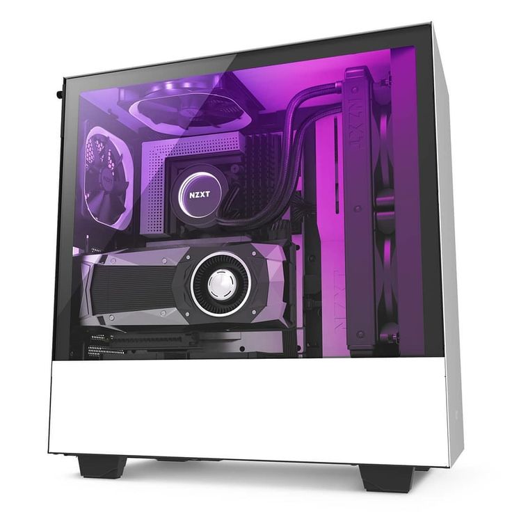 This design fits with all types of GPU cards (mine is a Radeon R9 390X). I've provide the skp file if you want to rework it with SketchUp.
... Whole PC wall mount project is available...
This design fits with all types of GPU cards (mine is a Radeon R9 390X). I've provide the skp file if you want to rework it with SketchUp.
... Whole PC wall mount project is available...
Vertical GPU Mount
thingiverse
Edited GPU mount by "GregTheGreatOne" for my computer case. Added some thicker corners if i need to add some screws to secure it. Aiming to use the added fin to secure in the card slot area. Will need to be customized further, this will be a first...
GPU Vertical Mount - V3
thingiverse
### VERSION 3 ### * Stronger than VERSION 1 & 2 * Fits 120 mm fan drilling * Attaching the GPU: 3 holes with a diameter of 5 mm for threaded rods. * Attaching the mount: 4 holes with a diameter of 5 mm incl. ...50 mm high spacers
GPU Vertical Mount - V2
thingiverse
### VERSION 2 ### #### [CHECK OUT THE NEW AND STRONGER VERSION 3](https://www.thingiverse.com/thing:3157988) #### * Fits 120 mm fan drilling * Attaching the GPU: 2 holes for 6-32 UNC (threaded) screws. * Attaching the mount: 4 holes with a diameter...
GPU Vertical Mount - SLI
thingiverse
#### Intro A vertical GPU mount for SLI. I designed this mount in from scratch, using an old case to get the dimensions for the PCI slots and the alignment of the riser cables. I actually designed this in December 2017. I searched on Thingiverse for...
Vertical GPU Mount
thingiverse
Remix of NICKOPOL411 design. ...recreated to fit a 120mm fan mount and relocated the end mounting screws. ... 123D Design source file included.
Vertical Gpu mounting bracket case back plate
thingiverse
... back plate used to support the graphics card and clean up the back of my case. Youtube video of the vertical gpu mod https://youtu.be/aymNFQSKbVI Here is a link to the vertical gpu mount I designed as well https://www.thingiverse.com/thing:2434186
Vertical GPU Mount Meshify C
thingiverse
This is a bracket designed to allow vertical GPU mounting in the Fractal Design Meshify C and Define C case. You will need to cut a hole in the hexagon mesh panel of the area next to the PCIe slots.
Slide the mount in from the outside and use fan...
You will need to cut a hole in the hexagon mesh panel of the area next to the PCIe slots.
Slide the mount in from the outside and use fan...
Vertical GPU Mount Ver. 2
thingiverse
This still does not require any modifications to the case BUT it now has the option for height adjustment to fit the GPU accordingly with those bulky cpu heatsink coolers. This also requires some screws to attach it inside the case, as well as...
GPU Bracket
thingiverse
GPU Brackets designed to fit 65mm cable hole for PC
GPU bracket
thingiverse
GPU Bracket for most Nvidia GTX graphic cards. ... 1xHDMI
3xDisplay port
Enjoy :)
--
Marc
... 1xHDMI
3xDisplay port
Enjoy :)
--
Marc
Corsair Crystal 280X Vertical GPU Mounting bracket and Support
thingiverse
Hello all, Here is the vertical GPU bracket I designed for the Corsair Crystal 280x case. Edit- Printing with PLA, the bracket will sag from the computers heat, so make sure you also use a GPU support which helps to stop this. If the bracket does...
GPU Vertical Mount - PC Custom Case
thingiverse
I built a custom PC case and relocated the GPU using one of these PCI Express riser cables: https://amzn. to/2E9GIUd (affiliate link) https://www.amazon.com/gp/product/B07CS59X7Y/ref=ppx_yo_dt_b_asin_title_o07__o00_s02?ie=UTF8&psc=1 (regular link) I'm...
Universal Vertical GPU Mount Amd Nvidia
pinshape
Universal 3d printed vertical GPU mount for Amd or Nvidia cards. Compatible with cases with 7 pcie slots and 2 slot cards. This is also compatible with the screws that come out of your PC slots so no special hardware needed. A riser card will be...
GPU Bracket
thingiverse
It's a GPU bracket to stop sagging which could potentially destroy your PCIE Slot on your motherboard, I hope it can help in some way!
I've printed mine with PETG, 15%, Supports On and it come out fine and does the job for me! . ..I assume it would...
GPU Bracket
prusaprinters
It's a GPU bracket to stop sagging which could potentially destroy your PCIE Slot on your motherboard, I hope it can help in some way! I've printed mine with PETG, 15%, Supports On and it came out fine and does the job for me! ...I assume it would print...
Corsair Air 540 Vertical GPU Mount
thingiverse
This is my design for a vertical GPU mount for the Corsair Air 540 case that will allow full use of other PCIe slots on the motherboard. The bracket where the IO plate attaches is universal for any dual slot bracket. It should fit any case since it. ..
..
3-slot GPU Vertical Mount Adapter
thingiverse
... so the PCIe ribon doesn't have to go too far sideways. ... **DOES REQUIRE CASE MODIFICATION** and the three slots were slightly off in the original (required some force to get the GPU to drop into the adapter) My first submission to Thingiverse.
GPU bracket
thingiverse
Bracket for sagging GPUs. Please double-check your card/case before printing (mine are carbide air 540 and hydrocopper 770), as you may need some tweaks if you have different hardware. Hole to hole distance is 19 mm, total length 126 mm; upper hole...
RVZ03 case gpu vertical mount 3x80mm
thingiverse
Silverstone RVZ03 case gpu verticalmount 3x80mm fans You have to drill holes or glue back panel to case and the back panel needs support You need this type of pci riser cable: Fractal Design Flex VRC
RVZ03 case gpu vertical mount 3x80mm
thingiverse
Silverstone RVZ03 case gpu verticalmount 3x80mm fans You have to drill holes or glue back panel to case and the back panel needs support You need this type of pci riser cable: Fractal Design Flex VRC
GPU VERTICAL
grabcad
Gpu vertical
3D Printed PCB Test Bench
Here is an article describing a homemade modular fixture designed to test assembled PCBs. The material was prepared by Mauro Laurenti for PCBWay.
The design phase is the most important part of the development cycle and requires a lot of time to get a quality product. However, testing new systems requires no less attention and time than design.
The only way to properly verify the interaction of components is by testing a real sample. Last but not least, testing allows you to check the usability of systems. This article will introduce a 3D printed fixture for testing assembled circuit boards. The bench is designed for versatility and can be used in a variety of scenarios where you need to quickly test an assembly and replace components if necessary.
General description
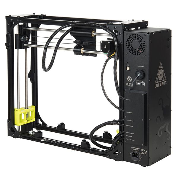
The illustration below shows a typical fixture assembly. Please note that the device is similar to a construction kit with the ability to install additional elements.
The platform has slots for universal fasteners, allowing you to adjust to boards of different sizes with the ability to install several boards at the same time. Installation of boards is possible both in horizontal and vertical position.
Platform can be 3D printed. The thickness of the plate is recommended to be chosen within 3-5 mm, as this range gives the best combination of strength and 3D printing time. The thickness of the sample in the illustration is 3 mm.
The platform is mounted on a laboratory table using five legs located at the corners and in the center of the platform. The legs can either be screwed to the table or fixed with double-sided tape. All connections are equipped with rotary knobs, so that the fixture can be assembled without a screwdriver.
Why is it needed
Attachment accepts one or two junction panels for quick connection to power supply and connection/disconnection of signal cables. Connection panels are available in two versions. The first is a blank without holes, which can be customized for your own needs. The second option already has six holes for banana plugs - in most cases this is enough.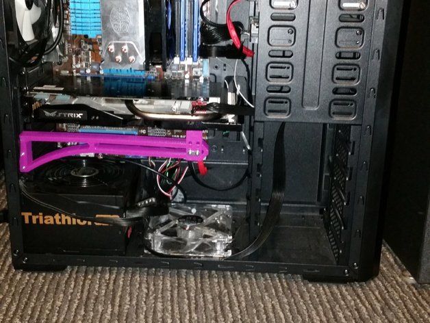 The connection panel can be connected to the PCB under test using the required connectors/adapters. This approach makes it easy to mount and connect different printed circuit boards without the need for new cabling.
Testing means not just fixing the board, but also collecting data while the system performs its intended functions. In this regard, the connection panel also helps, allowing you to easily connect the multimeter and power supply. As a rule, the current consumption is measured first. In complex systems, it may be necessary to check for potential short circuits or measure the impedance between key points. A secure board fixation helps with this kind of work.
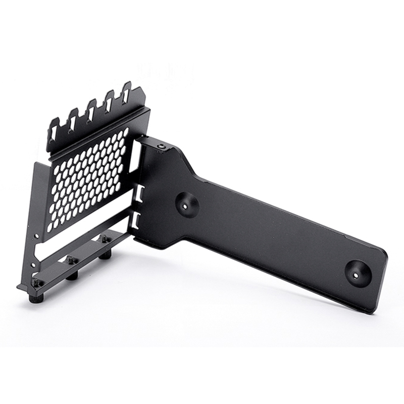
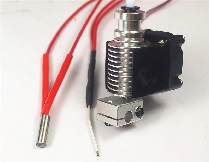
As testing progresses, the user may not be able to use two hands, in which case a tool will be required to secure the probes. The articulated mount shown in the illustration above will help with this.
The high flexibility of these mounts facilitates positioning when changing from one measurement to another.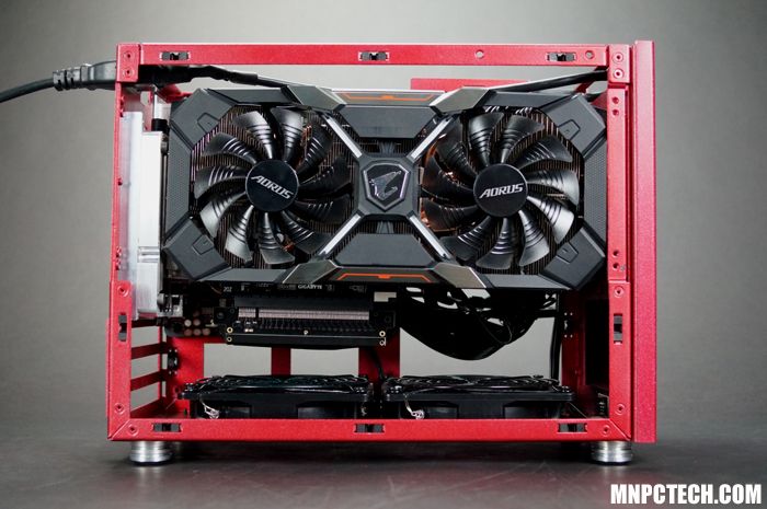 If desired, you can use additional moving sections or add springs so that the probes are pressed more tightly against the contacts.
Assembly parts
Below is a list of all available attachment components. Any of them can be printed on a 3D printer, additional elements can be easily designed independently. The files are offered free of charge and can be freely distributed and used in both personal and commercial projects, provided that the author is credited. STL files can be downloaded from this link.
Platform
Filename: Main Plate - 3mm
Quantity: 1 pc.
Description:
This is the main carrier with holes for fixing the board and additional tools. The thickness of the plate is recommended to be set within 3-5 mm with a filling of 25%. The 3mm version has been successfully tested and offers a good compromise between durability and 3D printing time.
Leg
File name: Foot - A
Quantity: 5 pcs.
Description:
Feet are installed in each corner and in the center of the main plate. In the upper part there is a hole with a diameter of 6 mm for a brass threaded insert M4. On the side there is a similar hole for connecting the legs and desktop mount. At the bottom there is another threaded hole for M4 plastic screws for EMC testing.
Table mount
File name: Foot holder – A
Quantity: 4 pcs.
Description:
Table mount is designed for rigid connection of the legs to the table. The legs themselves and the platform can be moved, but the table mounts must be either screwed to the table or glued with double-sided tape.
Connection panel
File name: Connector Panel - B
Quantity: 1-2 pcs.
Description:
The connection panel serves as an interface between the signal and power cables of the measuring instruments with the board under test.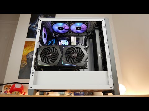 Option B already has six seats, and option A is a blank in which you need to make holes yourself.
Handles
File name: Knob - A and B
Quantity: 20 type A and 25 type B
Description:
Type A has a 6 mm socket for M4 brass threaded inserts, and type B has a through hole with a socket for an M4 nut. Screws 18-25mm long will be required depending on the assembly configuration.
Board holder
File name: PCB holder
Quantity: 4 pcs.
Description:
These fasteners are designed to fix printed circuit boards on a platform with the possibility of horizontal or vertical installation. Type A helps keep the board 5cm off the ground for EMC testing in accordance with CISPR 25.
Arm base
File name: Probe Arm - base
Quantity: 4 pcs.
Description:
This part serves as the base for a flexible articulated mount capable of holding both probes and boards.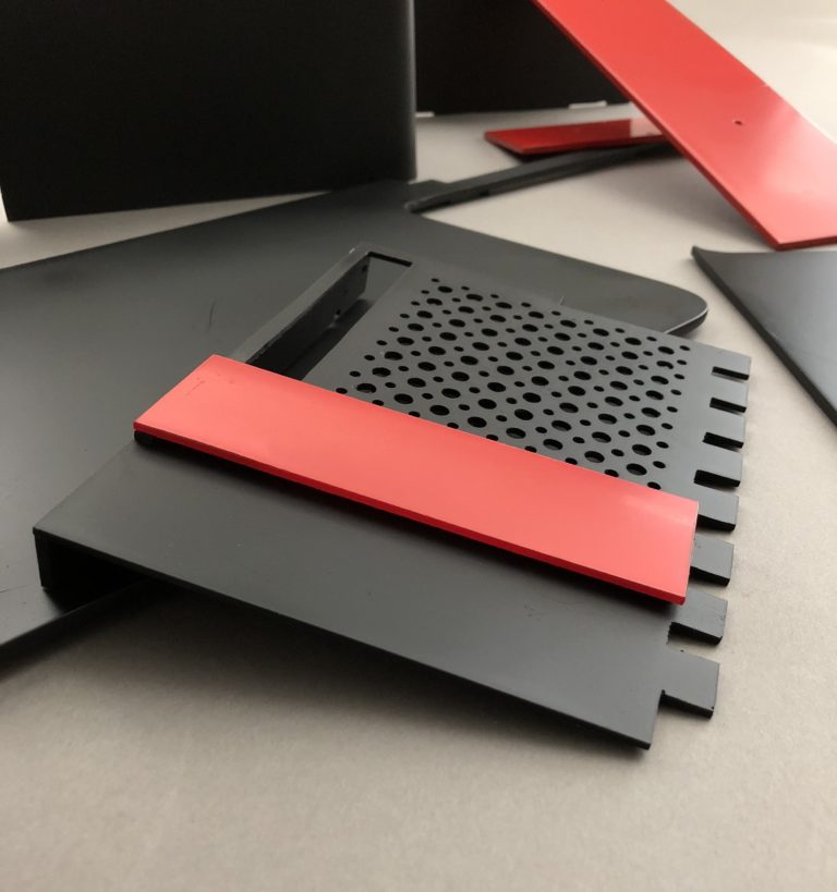 In the lower part there is a seat with a diameter of 6 mm for a brass threaded insert M4.
Arm segment
File name: Probe Arm - front - A
Quantity: 4 pcs.
Description:
The part serves as the movable segment of the articulated mount and can be used to fix the board horizontally or vertically.
Arm segment
File name: Probe Arm - L
Quantity: 4 pcs.
Description:
Used to change the direction of movement of the articulated mount.
"Hand" grip
File name: Probe holder – A
Quantity: 2 pcs.
Description:
End piece of the articulated mount, directly responsible for holding the probes. If required, this part can be screwed directly onto the cable management platform. In the lower part there is a seat with a diameter of 6 mm for a brass threaded insert M4.
EMC testing
PLA device can be useful for EMC testing.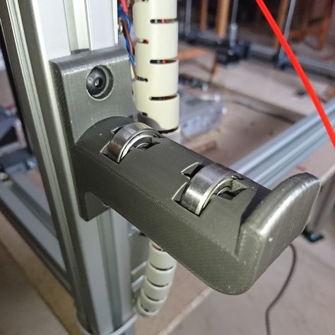 In particular, when using horizontal mounting, PCB height above ground meets the 5 cm minimum in CISPR 25 requirements. The required dielectric constant of the retaining material is Ԑr<1.3, while PLA typically has Ԑr in the range of 2-3. Since the PLA platform is 3 to 5 mm thick and there is only air underneath, the average value of Ԑr may be less than required by CISPR 25. If the test bench is made of a material with a higher dielectric constant, you will measure higher common mode noise than with the required Ԑr<1.3, but this is acceptable for pre-compliance testing as this would be the worst case scenario.
When CISPR 25 tests are being performed for pre-compliance testing purposes, or simply for conducted noise testing and input EMI filter selection, it is important that all screws and threads are non-conductive.
Another interesting scenario concerns the use of the fixture for fixing electrical and magnetic sensors. In this case, too, it is important to use plastic screws to limit the effects of electric and magnetic fields.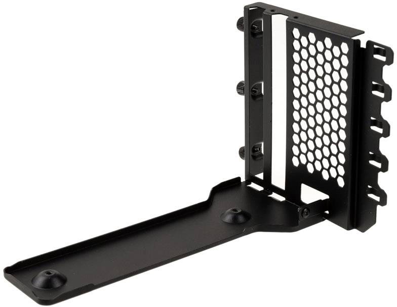 If the magnetic field is most important, brass fasteners are not as problematic as screws made of ferroelectric materials. If the main value is played by the electric field, all metals should be avoided. As a rule, high-current systems with large current drops are more likely to be sources of magnetic fields, and strong voltage fluctuations form electric fields. However, electric and magnetic fields are related by Maxwell's equation, so be careful if you decide to ignore one of the components of the electromagnetic field.
A couple of useful considerations:
1. Standard PLA is not considered an antistatic material, so when working with sensitive boards, I would recommend either applying an antistatic coating to the parts or using specialized antistatic variants of polylactide filaments. The use of metallization of parts is also not recommended.
2. In the event of strong discharges, such as a short circuit, the PLA may melt. A similar result is possible in the case of insufficient heat removal. To avoid a fire, you must:
- do not leave connected boards unattended;
- try to use the minimum required electrical power during testing;
- use fuses as far as possible in case of short circuits.
Safety regulations may vary from location to location, but must be observed in any case. The UL regulation requires, for example, "mandatory" fuse protection in cases where flammable materials are used and there is a possibility of exceeding the power rating. Alternatively, consider using UL 9 fire rated filament for 3D printed partsfour.
Author: Mauro Laurenti. Material provided by PCBWay.
Do you have interesting news? Share your developments with us, and we will tell the whole world about them! We are waiting for your ideas at [email protected].
My 3D Printed Marble Machine / Sudo Null IT News
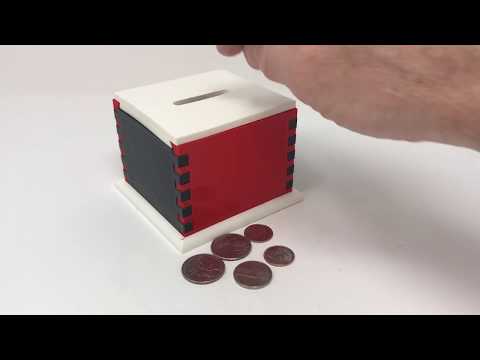
I'm trying to master 3D printing - I got a FLSUN-QQ printer, I installed 3D editors for myself: Fusion 360, Blender, I'm trying Compass 3D.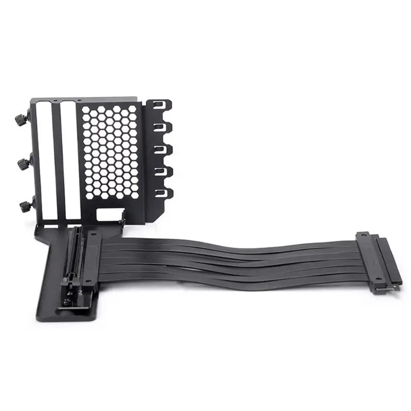 Something works, something doesn't work. This Marble Machine on video is one of my first successful projects. The project, although visually not large, but its implementation required considerable effort from me. I also had to master 3D editors and invent mechanics and set up and debug this device.
Next, I will tell you what parts this machine consists of.
The most important part is, of course, the upward spiral. She had the most problems. I have designed many different types of coils and many versions have been rejected for either aesthetic or technical reasons. Yes, even due to the fact that the promised printing time was too long, I had to give up various ideas ... I wanted to get something airy, beautiful and so that I could print on my printer in a reasonable time.
The final model of the coil looks like this:
The coil installed on the machine:
There were several problems with the coil. First, it was necessary to decide what profile the spiral should have. Several options were considered. The simplest of them can be schematically presented in a section like this:
Here is the thing - in the first version, if the border near the shelf protrudes strongly, then the printer software, and I use Ultimaker Cura, will make me supports that will need to be removed manually, and then if it is poorly cleaned, then they will also prevent the ball from rolling. If we take the second option with a thickening shelf, so that the ball seems to roll down to the plane of the spiral, then there will definitely not be any supports, but it is not known how well the ball will be held. I even printed a fragment of such a spiral to see how it would be in real life. But all the same, the third option won, an intermediate one, with a border / curb in the form of a corner. If it is not made very large, then the printer manages to print this without support.
Another problem with the spiral printing was purely manufacturing. I have never been able to print it in its entirety. I'm not sure what the reason is - it is possible that such a figure has too much cooling surface. While the extruder will pass along the entire trajectory, part of the model has probably already cooled down significantly. But these are just my guesses. Moreover, which is strange, at the very table, which is heated, the printing is normal, but the printing rises higher and plastic delaminations appear. At the same time, the printing of small test models occurred without problems. It’s not very pleasant when I started typing and everything seems to be going well for an hour. You leave to print for the whole day (another 13 hours of printing) until you leave for work. You come home, the printing is finished, but it turned out to be a marriage - the model has stratified on the upper layers. I even thought about printing a spiral in sectors, and then gluing it together. However, later I managed to pick up the print modes, temperature and speed, when the print went completely from start to finish with an acceptable result.
 There were a few toffee hairs left, it would be necessary to clean them all, but then I was a little too lazy.
Another question was how to make the spiral spin. As you can see, a gear goes along the edge of the spiral. To be honest, I didn't really expect it. I thought the main thing was to make teeth on the edge of the spiral, and then somehow give rotation from a toy collector engine with another gear. This idea didn't work for me for several reasons. Firstly, the gears still need to be pre-calculated. Secondly, the idea was almost implemented like this:
But then it turned out that it was not easy to regulate the speed of the collector motor, then, the shaft of the toy motor backlashed quite a lot, and it made an unpleasant noise in operation. In general, this idea was abandoned. I took a 28BYj-48 stepper motor with a motor driver:
Step control made on Verilog in the FPGA board Mars rover:
If anyone is interested in how to program stepper motor control on Verilog, then this is the topic of a separate article. Now the speed can be easily programmed and runs almost silently. Only now it is a pity that when printing a spiral, a significant amount of printing time was spent on printing the gear. I think without it I would have saved 2 hours of printing.
So, the 28BYj-48 stepper motor is installed in a special rack. The rack model I designed looks like this:
In the car, the stand with the engine looks like this:
but at least save a little printing time. Although, what a time saving there is, if you remember that the first version of the rack, which was supposed to be used in the version with a collector motor, was like this:
The problem with this rack is a large play of the spiral shaft. Well, again, as I already wrote, the option with a commutator motor and a gear did not work, so I had to make a new rack for a stepper motor.
It just so happens that I printed almost every detail at least twice. The first option, even if almost a worker had to be rejected often. Here, for example, is the “snake” part:
It would seem that this might not be the case, but it turned out that when the ball descends in a straight line, it accelerates decently and flies out due to centrifugal force. I had the first turn to increase the height of the side. Well, at the same time, when re-printing, I reduced the height of the print layer. Let it print longer and better. Here is the "snake" installed in the car:
The project also required buns for attaching M4 studs:
These buns are attached to the board with double-sided tape - it turned out pretty strong. It's funny that I printed the quadruple buns twice. At first I printed it with black plastic and with a little infill. The model stuck so tightly to the 3D printer table that while tearing it off, it bent a little. And that's all - it does not stand exactly on the table. But it’s good that I reprinted it, it seems to me that combining white and black was a good idea.