3D welding printer
Researchers Develop a Low-Cost Metal 3D Printer Using MIG Welding - 3DPrint.com
Metal 3D printing, although it has gone down in cost, is still quite expensive. This limits access to the technology for small and medium-sized businesses, meaning that many applications go untried. In a paper entitled “Design and Development of a Low-Cost 3D Metal Printer,” a group of researchers discuss how they created a low-cost metal 3D printer that utilizes metal inert gas (MIG) welding and an open source microcontroller to fabricate parts.
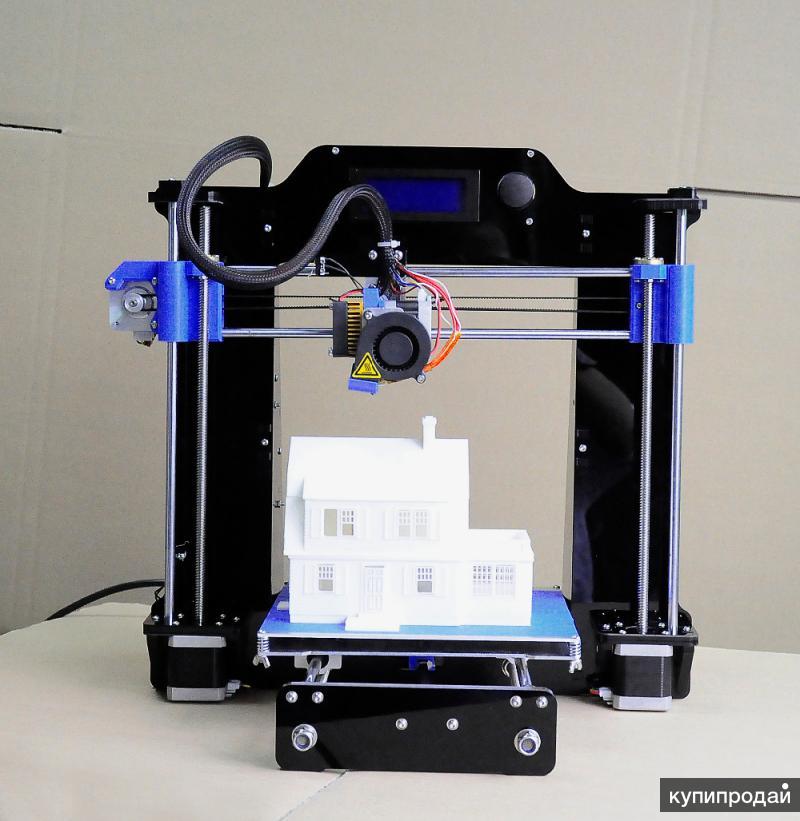
The researchers took the design of their 3D printer from a Prusa i3 system and used several off-the-shelf components to build it.
“The components consist in developing 3D metal printer machine are; a pair of bearing holder and motor bracket, motor casing, shaft holder, ball screw, coupling, limit switch, linear bearing, stepper motor, polyurethane cylinder, polytetrafluorethylane (PTFE) plastic cylinder and various fastener,” they explain.
![]()
A MIG welding machine was used to supply the material and the energy to melt the material. The movement of the printer and the translation of command from the printer’s server to the host computer was controlled by firmware provided with an Arduino microcontroller. The cost of the entire system was about RM 3496, which translates to roughly $840, much more affordable than a typical metal 3D printer.
“In order to ensure the metal print is connected during operations, the MIG welding was set to switch on and off automatically,” the researchers continue. “The shielding gas was set to flow before the printing process starts. The welding torch was placed under the fixture design perpendicular to the bed to build the surface. The distance between the bed surface and nozzle was adjusted to about 6 mm by leveling the height of the welding torch.”
The MIG welding machine begins building a part layer by layer, from bottom to top. In order to test the system, the researchers performed two experiments in which a cylinder and a rectangle were 3D printed.
“The aim for the first experiment is to find the suitable voltage during 3D printing that produce relatively good bead geometry of 3D printed part,” the researchers state. “At first, the welding was deposited along the custom cylinder design. The parameter used for welding voltage varied from 18.5 V to 22.5 V. The first experiment was done with a constant speed of 50 mm/s and current of 100 A. The final dimensions were taken and compared with the actual CAD data. The second experiment was designed so that capability of the newly developed machine to 3D print a rectangular shape can be analyzed. The aim of the second experiment is to find the suitable value of speed in producing good structure.”
Five samples were 3D printed for the first experiment and their average values were recorded. They found that porosity occurred when voltage was either to high or too low, and that higher voltages reduce the size of the specimen due to the excessive flow of the molten metal. A voltage setting of 20.5V produced a good quality part, but it was not dimensionally accurate. In the second experiment, the researchers attempted to find the best printing speed. A too-slow speed resulted in a rough surface and poor fusion. They found that the speed should not be any higher than 20mm/s, however, so that the liquid had time to solidify. Post-processing was required in all cases to get better surface finish. As you can see the results are far from perfect but at this price point many would be able to try to improve such systems. Given more time and investment this could very well be a viable alternative to some metal parts.
Output of printing process (a) speed at 20 mm/s, (b) speed at 40 mm/s, (c) speed at 60 mm/s, and (d) speed at 80 mm/s
“Nevertheless, the study demonstrated that simple design specimens were successfully fabricated using the MIG welding and 3D printing process,” the researchers conclude. “The microstructure shows that the layer perfectly coincides with each printer layer and the top region of manufactured layer has the lowest hardness compared to the initial layer.
However, further research needs to be done in the future to improve the product’s quality and to study the mechanical behavior of the parts produced by this technique.”
Authors of the paper include N.A. Rosli, M.R. Alkahari, F.R. Ramli, S. Maidin, M.N. Sudin, S. Subramoniam and T. Furumoto.
Discuss this and other 3D printing topics at 3DPrintBoard.com or share your thoughts below.
Stay up-to-date on all the latest news from the 3D printing industry and receive information and offers from third party vendors.
Tagged with: low-cost 3d printers • metal 3d printer • mig welding • Prusa i3 • welding
Please enable JavaScript to view the comments powered by Disqus.
Students Combine Prusa i3 Printer with a MIG Welder to Create an Affordable Metal 3D Printer - 3DPrint.com
The technology behind 3D printing is still at an early stage, but progressing rapidly. One area where researchers and engineers are focusing their attention now is affordable metal 3D printing. Currently if you wish to fabricate an object out of metal you need to have access to a machine costing close to, if not more than, $1 million. Just like with plastic 3D printing, however, such machines are certain to drop in price as their capabilities expand. There is more than just money keeping these printers out of people’s homes and garages, however. Safety is also a major concern, as high temperatures, powerful lasers, and potential fumes all present dangers to users and their environments.
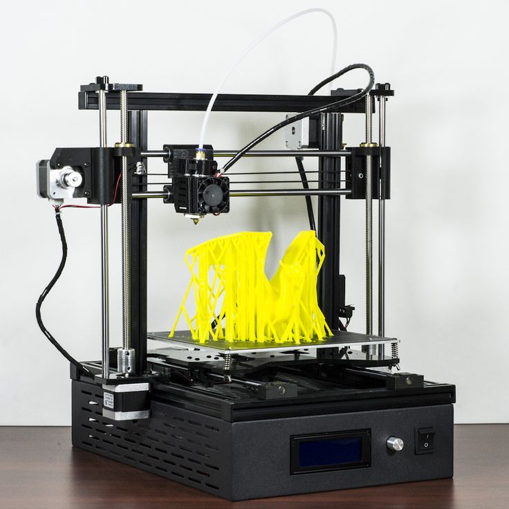
With that said, a group of students at Delft University of Technology are in the process of creating what they hope to be an open source metal 3D printer, available to a wide audience, and capable of printing with decent resolutions. The printer — which basically takes an MIG (metal/inert-gas) welder and attaches it to a Prusa i3 — is already capable of printing decent sized test objects.
For those of you unfamiliar with welding, an MIG welder uses a continuous feed of wire which is melted as it acts as both a filler metal and an electrode. A shielding gas flows around the melted wire, protecting it from any sort of local contamination.
The project, which has been inspired by research and development conducted at Michigan Technological University, already seems to be off to quite a start. Basically the MIG welder is tethered to the machine where the extruder and hotend usually are located. Using the Prusa i3’s Cartesian method of printing, the welder slowly but surely melts the metal wire as it places the material down layer by layer. The wire is fed to the welder at a rate of 4 meters/minute. The travel rate of the torch according to the team’s initial settings was 300mm/minute. A typical thermoplastic-based FDM/FFF printer, in contrast, can print anywhere from 3,000 to 18,000 mm/minutes, so this is considerably slower.
A 3D printed test object
Using this method, the team has been able to 3D print a wall-like structure, which is surprisingly solid, as well as uniform, which you can see from the images and video they have provided. Other circular shapes were also made.
There is still a tremendous amount of work to be done on this project; however, this certainly could act as a springboard toward affordable metal 3D printing. Let’s hear your thoughts on this project in the MIG Welder/3D Printer forum thread on 3DPB.com. Check out the video of the machine in action below. For further details and to follow along as the team progresses further on this project, check out their blog.
Stay up-to-date on all the latest news from the 3D printing industry and receive information and offers from third party vendors.
Tagged with: 3d metal printer • cheap metal 3d printer • delft university • metal 3d print • michigan technological university • open source 3d printer • tu delft • welder printer
Please enable JavaScript to view the comments powered by Disqus.
How metal 3D printers work. Overview of SLM and DMLS technologies. additive manufacturing.
 3D metal printing.
 Metal 3D printing. Additive technologies.
SLM or DMLS: what's the difference?
Hello everyone, Friends! 3DTool is with you!
BLT metal 3D printer catalog
Selective laser melting ( SLM ) and direct metal laser sintering ( DMLS ) are two additive manufacturing processes that belong to the family of 3D printing using the powder layer method. The two technologies have much in common: they both use a laser to selectively melt (or melt) metal powder particles, bonding them together and creating a pattern layer by layer. In addition, the materials used in both processes are metals in granular form.
The differences between SLM and DMLS come down to the basics of the particle bonding process: SLM uses metal powders with a single melting point and completely melts the particles, while in DMLS the powder consists of materials with variable melting points.
Specifically:
SLM produces single metal parts while DMLS produces metal alloy parts.
Both SLM and DMLS technologies are used in industry to create final engineering products. In this article, we will use the term "metal 3D printing" to summarize the 2 technologies. We will also describe the main mechanisms of the manufacturing process that are necessary for engineers to understand the advantages and disadvantages of these technologies.
There are other manufacturing processes for producing dense metal parts, such as electron beam melting (EBM) and ultrasonic additive manufacturing (UAM). Their availability and distribution is rather limited, so they will not be presented in this article.
How 3D printing with SLM or DMLS metal works.
How does metal 3D printing work? The basic manufacturing process for SLM and DMLS is very similar.
1. The printing chamber is first filled with an inert gas (such as argon) to minimize the oxidation of the metal powder. It then heats up to the optimum operating temperature.
2. A layer of powder is spread over the platform, a powerful laser makes passes along a predetermined path in the program, fusing the metal particles together and creating the next layer.
3. When the sintering process is completed, the platform moves down 1 layer. Next, another thin layer of metal powder is applied. The process is repeated until the entire model is printed.
When the printing process is completed, the metal powder already has strong bonds in the structure. Unlike the SLS process, parts are attached to the platform via support structures. The support in metal 3D printing is created from the same material as the base part. This condition is necessary to reduce deformations that may occur due to high processing temperatures.
When the 3D printer's chamber cools down to room temperature, excess powder is removed manually, such as with a brush. The parts are then typically heat treated while they are still attached to the platform. This is done to relieve any residual stresses. They can then be further processed. The removal of the part from the platform occurs by means of sawing.
Scheme of operation of a 3D printer for metal.
In SLM and DMLS, almost all process parameters are set by the manufacturer. The layer height used in metal 3D printing varies from 20 to 50 microns and depends on the properties of the metal powder (fluidity, particle size distribution, shape, etc. ).
).
The basic size of the print area on metal 3D printers is 200 x 150 x 150 mm, but there are also larger sizes of the working area. Printing accuracy is from 50 - 100 microns. As of 2020, metal 3D printers start at $150,000. For example, our company offers 3D metal printers from BLT.
metal 3D printers can be used for small batch production, but the 3D printing capabilities of such systems are more like those of mass production on FDM or SLA machines.
The metal powder in SLM and DMLS is recyclable: typically less than 5% is consumed. After each impression, the unused powder is collected and sieved, and then topped up with fresh material to the level required for the next production.
Waste in metal printing, are supports (support structures, without which it will not be possible to achieve a successful result). With too much support on the manufactured parts, the cost of the entire production will increase accordingly.
Adhesion between coats.
3D metal printing on BLT 3D printers
SLM and DMLS metal parts have almost isotropic mechanical and thermal properties. They are hard and have very little internal porosity (less than 0.2% in 3D printed condition and virtually non-existent after processing).
Metal printed parts have higher strength and hardness and are often more flexible than traditionally made parts. However, such metal becomes “tired” faster.
3D model support structure and part orientation on the work platform.
Support structures are always required when printing with metal, due to the very high processing temperatures. They are usually built using a lattice pattern.
Supports in metal 3D printing perform 3 functions:
• They form the basis for creating the first layer of the part.
• They secure the part to the platform and prevent it from deforming.
• They act as a heat sink, removing heat from the model.
Parts are often oriented at an angle. However, this will increase the amount of support required, the printing time, and ultimately the overall cost.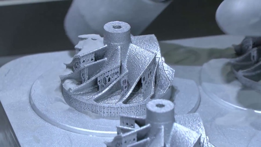
Deformation can also be minimized with laser sintering templates. This strategy prevents the accumulation of residual stresses in any particular direction and adds a characteristic surface texture to the part.
Since the cost of metal printing is very high, software simulations are often used to predict how a part will behave during processing. These topology optimization algorithms are otherwise used not only to increase mechanical performance and create lightweight parts, but also to minimize the need for supports and the likelihood of part distortion.
Hollow sections and lightweight structures.
An example of printing on a BLT 3D printer
Unlike polymer powder melt processes such as SLS, large hollow sections are not typically used in metal printing as the support would be very difficult to remove, if at all possible.
For internal channels larger than Ø 8 mm, it is recommended to use diamond or teardrop cross-sections instead of round ones, as they do not require support. More detailed recommendations on the design of SLM and DMLS can be found in other articles on this topic.
As an alternative to hollow sections, parts can be made with sheath and cores, which in turn are machined using different laser power and pass speeds, resulting in different material properties. The use of sheath and cores is very useful when making parts with a large solid section, as it greatly reduces printing time and reduces the chance of warping.
The use of a lattice structure is a common strategy in metal 3D printing to reduce part weight. Topology optimization algorithms can also help design organic lightweight shapes.
Consumables for 3D metal printing.
SLM and DMLS technologies can produce parts from a wide range of metals and metal alloys, including aluminum, stainless steel, titanium, cobalt, chromium and inconel. These materials meet the needs of most industrial applications, from aerospace to medical applications. Precious metals such as gold, platinum, palladium and silver can also be processed, but their use is of a minor nature and is mainly limited to jewelry making.
The cost of metal powder is very high. For example, a kilogram of 316 stainless steel powder costs approximately $350-$450. For this reason, minimizing part volume and the need for supports is key to maintaining optimal manufacturing cost.
The main advantage of metal 3D printing is its compatibility with high-strength materials such as nickel or cobalt-chromium superalloys, which are very difficult to machine with traditional methods. Significant cost and time savings can be achieved by using metal 3D printing to create a near-clean shape part. Subsequently, such a part can be processed to a very high surface quality.
Metal post-processing.
Various post methods. treatments are used to improve the mechanical properties, accuracy and appearance of metal printed products.
Mandatory post-processing steps include the removal of loose powder and support structures, while heat treatment (heat annealing) is typically used to relieve residual stresses and improve the mechanical properties of the part.
CNC machining can be used for critical features (such as holes or threads). Sandblasting, plating, polishing, and micro-machining can improve the surface quality and fatigue strength of a metal printed part.
Advantages and disadvantages of metal 3D printing.
Pros:
1. Metal 3D printing can be used to make complex custom parts, with geometries that traditional manufacturing methods cannot provide.
2. Metal 3D printed parts can be optimized to increase their performance with minimal weight.
3. Metal 3D printed parts have excellent physical properties, metal 3D printers can print a wide range of metals and alloys. Includes difficult-to-machine materials and metal superalloys.
Cons:
1. Manufacturing costs associated with metal 3D printing are high. The cost of consumables is from $ 500 per 1 kg.
2. The size of the working area in metal 3D printers is limited.
Conclusions.
• Metal 3D printing is most suitable for complex, one-piece parts that are difficult or very expensive to manufacture using traditional methods, such as CNC.
• Reducing the need for building supports, will significantly reduce the cost of printing with metal.
• 3D printed metal parts have excellent mechanical properties and can be made from a wide range of engineering materials, including superalloys.
And that's all we have! We hope the article was useful to you.
Catalog of 3D printers for metal BLT
You can purchase metal 3d printers, as well as any other 3d printers and CNC machines, by contacting us:
• By email: Sales@3dtool.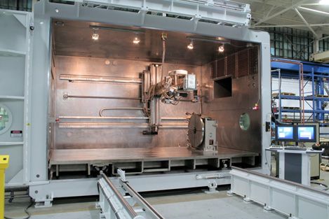 ru
ru
• By phone: 8(800)775-86-69
• Or on our website: http://3dtool.ru
Also, don't forget to subscribe to our YouTube channel:
Subscribe to our groups in social networks:
In contact with
How to make a metal 3D printer for less than $1000
News
A team of scientists from Malaysia and Japan published a report on the construction of an ultra-budget 3D printer for metal printing. What we need: a Prusa i3 clone, a welding machine, a roll of blue electrical tape, a fire extinguisher and a few other little things. We share the recipe.
There are many methods for 3D printing with metals: selective laser sintering or deposition of metal powder compositions, the same thing, but using electron beam guns, direct laser deposition, inkjet-powder printing followed by binder burning and sintering, cold gas-dynamic spraying and others.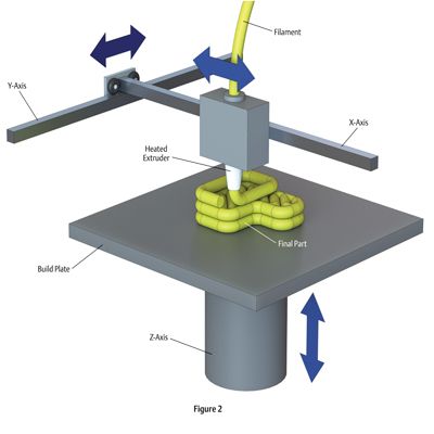 One of the methods is based on the layer-by-layer growth of products by arc welding in a protective gaseous environment. This technology is notable for its high performance and low cost of consumables (metal wire instead of fine powders), but it is not without its drawbacks, the most obvious of which is the low quality of the surfaces of 3D printed products with the resulting need for intensive post-processing.
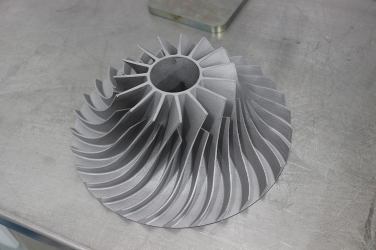
However, this technique has found its niche: the most striking examples can be found in the Netherlands, where MX3D has printed a metal bridge, and RAMLAB, a port facility in Rotterdam, supplies customers with spare parts for ships, including 3D printed propellers. In both cases, an industrial multi-axis robotic arm equipped with welding equipment acts as a 3D printer. It will be expensive. But why not try to screw the welding machine to the budget "drygostol"?
Researchers from the Technical University of Malaysia at Malacca and the National University of Japan at Kanazawa have taken on this task.