3D printing split model
How to Split & Cut STL Models For 3D Printing – 3D Printerly
Splitting and cutting your models or STL files for 3D printing is important if you want to create prints that are larger than your build plate. Instead of scaling down your project, you can separate your model into different parts which can later be joined together.
In order to split and cut your STL models for 3D printing, you can do this in many CAD software such as Fusion 360, Blender, Meshmixer, or even directly in slicers like Cura or Lychee Slicer. You simply select the split or cut function within the software and split the model where you choose.
This is the basic answer for splitting and cutting your model, so keep on reading to get the details on how to do this successfully, along with more useful information that you can use.
How Do You Break Up Models & STL Files for 3D Printing?
When it comes to 3D printing, breaking up large models is an important skill to learn since we are limited by the size of our build plates for each print.
Rather than stopping at this limitation, people figured out they could break models into smaller sections, which can then be glued back together afterwards. This can be done by using design software or even directly within our slicers, though it takes some knowledge to get it right.
It’s similar to having a model which is split with the main model and the base or stand of the model, but doing this for multiple parts of the model.
After you split and print the model, people tend to sand the prints down, then super glue them together to provide a strong bond that shouldn’t come apart.
Popular software that can split your STL files or models up are Fusion 360, Meshmixer, Blender, and many more. Some of these are easier than others, mainly due to the user interface or how many features the application has.
It’s best to pick a software and follow a good video tutorial that takes you through the steps to split up your models with ease. You can actually use the popular Cura slicer to split your models down and separate them into different STL files which can be printed separately.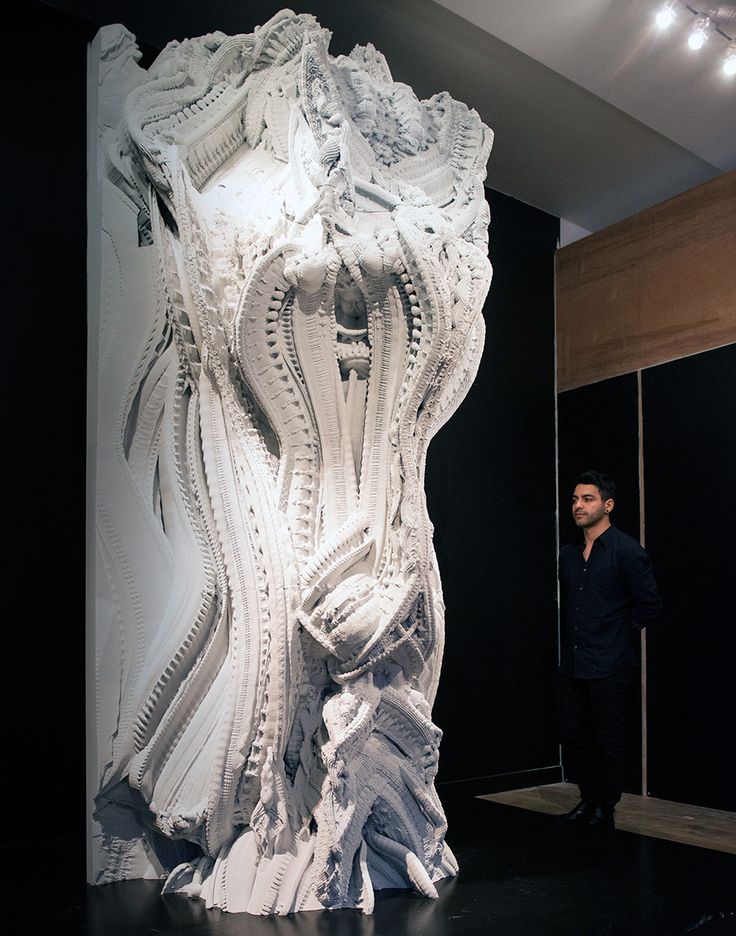
Similarly, you have resin slicers such as ChiTuBox or Lychee Slicer that have inbuilt split functions where you can cut a model and organize it on the build plate as you wish.
The process of splitting a model and changing the orientation can allow you to easily fit a large model on your build plate, by utilizing the whole area.
In some instances with more advanced model, designers actually provide STL files where the model is already split up, especially when it comes to figurines, complex characters, and miniatures.
Not only are these models split up nicely, but sometimes they have joints which fit together nicely like a socket, allowing you to easily glue them together. With experience and practice, you can even take STL files, edit them and make your own joints.
Let’s look into how to actually split models using different software.
How to Split a Model in Fusion 360
A simple way to split a model in Fusion 360 is to sketch where you want to split the model, Extrude the sketch towards the inside of your model, then change the Operation to “New Body”. Now you can hit the “Split Body” button with the Splitting Tool highlighted and select the model to split up the two separate parts.
Another way to split a model in Fusion 360 is to create an Offset Plane on your model under the “Construct” section in your toolbar, then move the Plane to where you want to split the model. You then click the “Split Body” button in the toolbar and select the Plane to cut. Each face of your model can have a Plane.
Check out the video below for a great illustration and tutorial on how to get this done for your models.
The video above shows how to split really simple models, though for more complex ones, you may want to use a more advanced technique to get the splits perfect.
The video below by Product Design Online takes you through two main methods on how to split large STL files so you can successfully 3D print them. It works for STL files or even STEP files that are large meshes.
Many people describe it as one of the best videos on how to split 3D printer files for printing.
The first method consists of:
- Measuring the Model
- Turning on the Mesh Preview
- Using the Plane Cut Feature
- Selecting the Cut Type
- Selecting the Fill Type
The second method consists of:
- Using the Split Body Tool
- Moving the Newly Cut Parts
- Creating a Dovetail
- Copying the Joint Type: Making Duplicates
How to Split a Model in Cura
To split a model in Cura, you first have to download a plug-in called “Mesh Tools” from the Cura Marketplace. After getting it, you simply choose your model, click on the Extensions tab and find Mesh Tools there. Finally, click on “Split model into parts” and enjoy your model cut into two.
Cura’s method for splitting up a model is quite uncomplicated. The older versions of this slicer software didn’t even require downloading the Mesh Tools plug-in.
You simply had to right-click on the model and the option to split your model would appear. Painless360 has explained how to break your model into parts in the following video.
Unfortunately, Cura does not involve advanced techniques to cut your model. You’ll have to use Meshmixer or Fusion 360 for more complex part splitting.
How to Cut a Model in Half in Blender
To cut a model in half in Blender, go to “Edit Mode” by pressing the “Tab” key, then find the “Bisect Tool” in the “Knife” section on the left column. Ensure the mesh is selected by pressing “A” then click the first and second point to create a line where your model will be cut. Now press “P” to separate the model.
- Go into Edit Mode by pressing the Tab key
- On the left column, find the “Knife” tool, hold the left click and select the “Bisect Tool”
- Make sure the mesh is selected by pressing the “A” key
- Create the line by clicking the first and last point across your model to start the split
- Press the “V” key then right-click to make the actual split in the model
- While the split is still highlighted, press “CTRL+L” to select the active mesh it’s connected to.
- You can also hold “SHIFT” and click any meshes if there are loose parts then hit “CTRL+L” to select it
- Hit the “P” key and separate parts by “Selection” to separate the parts in the model
- Now you can hit “TAB” to go back to Object Mode and move around the two separate pieces.
There are some options that you can play with while splitting up your models, though it’s very simple to do for the most part.
You can choose whether you want to keep the part of the model you are splitting by checking the “Clear Inner” or “Clear Outer” part of the model, as well as choose whether to “Fill” the mesh, so the split doesn’t just have a gap in there.
If you forgot to fill in your models during the splitting process, you can hold “SHIFT + ALT” then Left-Click the outer mesh or edge of the model to select the whole exterior or “loop select” the model. Now press the “F” key to fill in the mesh.
There are more tips that you can do to smooth your model and even make the edges match up better. Check out the video below by PIXXO 3D for a great tutorial on how to split models on Blender.
How to Separate Objects in Meshmixer
When it comes to creating complex cuts, doing it in a slicer or very basic CAD software can be difficult or just not possible. Meshmixer is a popular CAD software that allows you to have a lot more control over how you separate and split your 3D printing files.
To separate objects in Meshmixer, you have to click on the “Edit” section and choose “Plane Cut” from the options there. Then, select “Slice” as the “Cut Type” and separate the object using a plane cut. Go back to “Edit” and click on “Separate Shells.” You will now be able to easily “Export” the individually split models from the menu on the left.
You also have a second option to split models by using the “Select Tool” and specifying a smaller area of the model to be cut.
Josef Prusa has a great video showing you exactly how you can cut STL models successfully in Meshmixer.
Here is a summary step-by-step guide to separating objects in Meshmixer.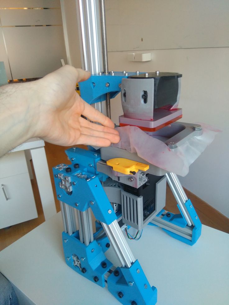
- First, import your model into the Meshmixer platform
- Select “Edit” & hit “Plane Cut”
- Rotate the view to identify the Plane you want to cut
- Click and drag to cut the model in the desired area
- Change the “Cut Type” to slice so you don’t discard any of the model and hit “Accept”
- Your model is now separated
- You can go back to “Edit” and select “Separate Shells” to split the model up
Another cool thing you can do in Meshmixer is to actually create aligning pins to your split models which fit like a plug between two pieces. This is also shown in the video above, so definitely check that out to learn how to do it like the pros.
Bonus Method: Use 3D Builder to Split 3D Models Easily
3D Builder is one of the easiest ways of splitting up an STL file and cutting it into different parts. It comes pre-loaded on most Windows computers, and can also be downloaded for free through the Microsoft Store.
The application enjoys a fluid, responsive interface with easy-to-understand controls that even beginners won’t have a difficult time getting used to.
To split a model in 3D Builder, simply select your model, click on “Edit” in the Taskbar above, and then click on “Split.” You would then use the rotation gyroscopes to position the cutting plane however you want. When done, click on “Keep Both” and select “Split” to cut the model in half and save it as an STL file.
3D Builder makes the splitting process quite effortless for 3D printing enthusiasts and experts alike. The cutting plane is easy to handle, and you can easily use it as your go-to model slicer, as thousands of other people do.
The following video can help illustrate the process even further.
How to 3D Print Models Larger than Your 3D Printer’s Build Volume
Don’t own a large format 3D printer yet? When determining what’s possible with a compact desktop 3D printer, think beyond the build volume. Just as assemblies such as your smartphone or even a road bridge consist of many individual building blocks, splitting a model into smaller parts that can be combined after printing is a great solution for 3D printing large objects that don’t fit on a build platform.
Splitting a part can also be the best way to get a high-quality result, even if the whole part could fit into a single build. This is the case when multiple or opposing surfaces need to be free of support marks, a design has complex overhangs, or a model contains cavities that would trap the liquid resin inside.
3D printing multiple pieces also opens up new opportunities, such as creating multi-material assemblies or combining rigid and flexible 3D printed parts to simulate overmolding.
When selecting a bonding method, your primary consideration should be the strength of the bonded joints, which is dependent on the ultimate use case of the parts:
-
Chemical fastening: Use a bonding agent for art, scale models, and complex shapes that are not meant for functional use and to sustain impact.
-
Mechanical fastening: Add screw thread or pockets to functional engineering parts that require a robust mechanical connection or if you need to repeatedly attach and detach components.
This guide will focus on creating large multi-piece stereolithography (SLA) 3D printed models using chemical fastening. Read on for a step-by-step walk through the process, from splitting your model to post-processing for a professional finish.
Formlabs’ Form 3L is the first affordable and easy-to-use large format 3D printer optimized for the reliable production of industrial-quality parts. The Form 3L SLA 3D printer offers a massive 30 cm x 33.5 cm x 20 cm build volume at an unprecedented value.
See the Form 3L
There are two methods we recommend for splitting models: Add features to your design that will allow the prints to align themselves, or simply split the parts with straight cuts, requiring you to align them during the fastening process.
Regardless of which method you choose, if you have a large number of parts it’s also a good idea to add a unique identifier (letters, numbers) to each part to help you solve the puzzle during assembly.
Use the CAD tool of your preference to split your 3D model and add basic aligners like slots, pins, grooves, recesses, and lips or more complex aligners like dovetails and cuts that follow existing creases in the model.
Adding aligners to a design can help when it comes to assembling parts.
In a perfect world these aligners make it simple to align and assemble your parts, but can lead to issues when they turn out even slightly different from your 3D models and don’t line up perfectly. Consequently, only use aligners if your printer can print dimensionally accurate parts that are unlikely to warp.
Splitting your 3D model along straight lines is less design-intensive than adding aligners. Straight cuts are also more forgiving when prints turn out slightly warped or have generally a higher degree of dimensional variation.
Adding identifiers to each part helps you solve the puzzle during assembly.
On the downside, straight cuts can be time intensive when it comes to assembly, as you have to manually align each part and make sure they remain in the correct position until the adhesive fully bonds them.
By default, the stereolithography (SLA) 3D printing process creates fully dense parts. Depending on your design, this might not be a requirement when 3D printing large objects. In such cases, 3D printing the outer shell or hollowing out your design are great ways to save a considerable amount of material and time. When printing hollow models with an SLA 3D printer, be sure to add venting holes to avoid creating pressure volumes with air and resin.
Sample part
See and feel Formlabs quality firsthand. We’ll ship a free sample part to your office.
Request a Free Sample Part
Hollowing out your model can save substantial time and material, as the printer will only need to print the outer shell.
Find out more on how to save material and time by hollowing out your 3D models.
We recommend three methods for bonding parts, depending on their size and ultimate use case:
| Epoxy (5-30 minute) | Cyanoacrylate (CA, Super Glue) | Resin | |
|---|---|---|---|
| Area to bond | Large | Small/Medium | Small |
| Paintable | Yes | Yes | Yes |
| Impact strength | Medium | Low | Low |
For the largest parts and the strongest adhesion, use 5-30 minute epoxy. It has the longest work time, which helps when adjusting the position of larger 3D printed parts, but also leads to an overall slower assembly process. Most 5-minute epoxies won't change shape after about five minutes and reach approximately 75 percent cure strength in less than an hour.
For the largest parts and the strongest adhesion we recommend epoxy.
The next option is cyanoacrylate (CA, or Super Glue), which creates a quick, reasonably strong bond making ideal for small- and medium-sized parts. Clean the part thoroughly before applying it to the surface, as CA does not bond dirty surfaces well. CA has moderate impact strength, but is not recommended for high-impact applications.
For smaller prints you can also simply use the liquid resin from your SLA 3D printer. Pour a small amount of resin into a tray from the bottle or cartridge, use a dropper or syringe to pick it up, and place it onto the surface to bond. Join the parts and wipe off any excess resin that might spill out around the edges. To solidify the resin and bond the parts, use a 5mw UV laser light pen (405nm wavelength) and direct it to the bonding area around the parts.
This method will create a chemical bond, just as if the part was printed on your SLA 3D printer, but is only applicable to small bonding surfaces as the low power light pen cannot penetrate the model deep enough to create a strong bond.
Note: When dealing with resins, make sure to wear protective equipment including appropriate eye protection and gloves.
Webinar
Formlabs 3D Model Manager Evan Fisher walks the viewers through CAD and PreForm tips for larger parts and introduces Form Wash L and Form Cure L for post-processing.
Watch the Webinar Now
Now that you’re finished assembling your model, the final step is post-processing. This step consists of geometric correction of the part to ensure it has an even surface true to your original 3D model and aesthetic finish to get a consistent painted surface.
Depending on the accuracy of your printer and the size of the printed parts, it’s almost inevitable to have slight voids or incorrections where the parts meet. Automotive putty (such as Bondo 907) sticks to the resin well and should be applied to the surface in thin layers to patch these inaccuracies. Alternatively, use resin to fill the seams and cure it using a UV pen. Sand lightly after each layer dries to help bring the part towards its final form.
Patching parts with automotive putty (red area on the image) will help you mend slight voids or incorrections in between parts.
Sanding will help you remove support marks and any remaining inaccuracies from your model. Start with carefully dry sanding the surface using ~150 grit sandpaper to remove large support marks and level the edges where parts meet. Once the part’s surface is even, wet sand it with ~320 grit sandpaper to remove all remaining layer lines. Move the sandpaper in a random motion to avoid creating a grain. In most cases these two steps will create a smooth enough finish, but you might continue increasing the sandpaper grit count by a factor of ~2 and wet sand the entire part until the surface reaches the desired smoothness.
Power sanding works best on large flat surfaces, but can easily destroy small features. For smaller parts we recommend manual sanding, for larger ones a combination of manual and power sanding.
For larger parts, a combination of power and manual sanding can save you considerable time. Power sanding works best on large flat surfaces, but can easily destroy small features, sharp corners, and the subtle contours characteristic of SLA printing. Power sanding also creates a lot of dust, so make sure to prepare the surrounding area.
Note: Power tools require your full attention and wearing protective equipment. It is very easy to leave the sander stationary and quickly wear down that area without realizing it.
Once you’re finished sanding your model, rinse it in soapy water to remove any dust or debris and dry it thoroughly before moving onto the last step.
Priming ensures paint adhesion to the surface and can alert you to where you may need to sand more or trim support marks you may have missed. Generic plastic primer in matte grey shows details exceptionally well—apply it to the surface in several thin coats for the best results. Continue sanding on critical areas, apply a light coat of primer again, and repeat this process until the full part has an even surface.
Note: When priming and painting, wear protective equipment including a respirator designed for paint fumes.
Generic grey primer shows details exceptionally well and will help you uncover spots where additional sanding is required.
Find out more about sanding and priming from our extended guide.
For a finish with multiple colors, you’ll need to mask your model. First, plan the order in which you will paint your model depending on the color, opacity, and size of the area that will have the specific color. Start with the smaller parts so you’ll need to cover less when painting the bulk of the area with the main color. Use painter’s tape for covering the edges and corners, and sheets of paper to cover larger sections faster. Tape guides (lasercut) can also be helpful to create clean lines, circles, and complex shapes.
When it comes to masking, figuring out the correct order is your first priority. In our case, the parts were first painted silver and the sections that would remain silver on the final part were then covered with painter’s tape to hide them from the next l
Just as with priming, apply several thin coats rather than one heavy coat for the best results. Most spray paints work best in warm, slightly humid, and not windy conditions, but always check the specific paint can or technical documentation for the manufacturer’s recommendations.
Consider the time the paint takes to dry: Let layers sit before applying the same color and allow the paint to dry fully before applying a new color.
The area we covered with painter’s tape remained the original silver color after its removal.
Learn the ins and out of painting 3D printed parts in our extensive guide
Wondering how it looks when all these pieces come together?
“Excuse me sir, but that R2-D2 is in prime condition, a real bargain.”
Formlabs Optical Systems Engineer Adrian Tanner 3D printed this R2-D2 replica consisting of 105 3D printed pieces on a Formlabs SLA printer. It even has working electronics inside, borrowed from the Form 2 — the galvo drivers to make the sounds, the cartridge dispenser for lights, and the Z axis driver for the dome motor.
White Paper
In this free report, we look at how in-house large-format 3D printing with the Form 3L stacks up against other methods of production, chiefly outsourcing and using FDM printers. We also compare costs between methods, and review when it would be best to bring the Form 3L in-house.
Download Now
The Form 3L large format 3D printer offers a 30 cm x 33.5 cm x 20 cm build volume for 3D printing massive industrial-quality parts.
Eliminate the turnaround time of outsourcing or the manual work of assembly for large scale 3D prints. Now you can 3D print large objects in one piece with the Form 3L, the first affordable large format 3D printer using SLA technology.
Curious to see how SLA parts perform? Explore our materials to learn more about SLA resins, and request a free sample part to experience SLA quality firsthand.
Request a Free Sample Part
3D friends of great objects.
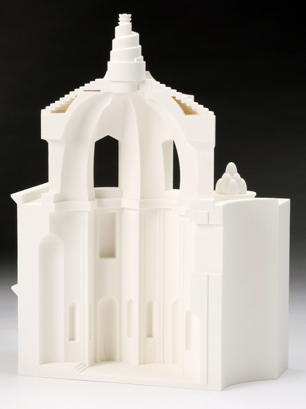 Company stats «3Dplast
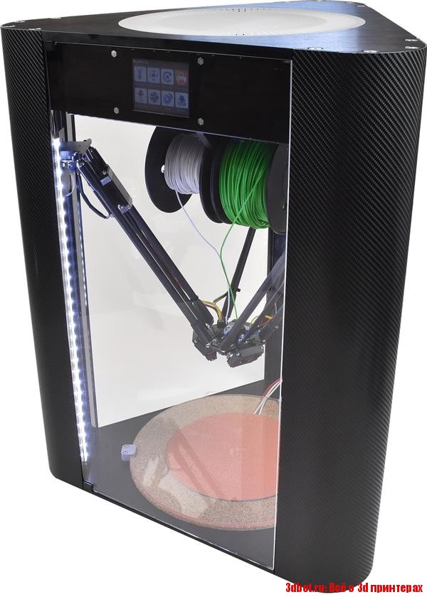
 Regardless of whether you want to enlarge your model or bring it to the proportions of 1: 1 in full size, you can get stuck with a serious physical problem: the size of a large camera, which you have, is insufficient.
Don't get lost, even if you're building large-scale projects, you can go beyond the help of a standard tabletop printer. A simple method, in such a way that you edit your models, draw and edit them, make great models with accessories for others on a large number of 3D printers.
If you want to be your partner and just look around for a bigger 3D printer, you'll get the stench. Ale їх or else it is not enough, but tse vzagalі testі zrazki. The most widely used printers can expand cameras 60 by 60 by 60 centimeters. So, it’s rich, paired with standard tables of 20 * 20 or 30 * 30 centimeters, but not less than that, you can get enough, so you need a meter copy of the Formula 1 car, for example.
Otzhe, how to entrust a great object on a great 3D printer? Time management has the same understanding of "drag the elephant.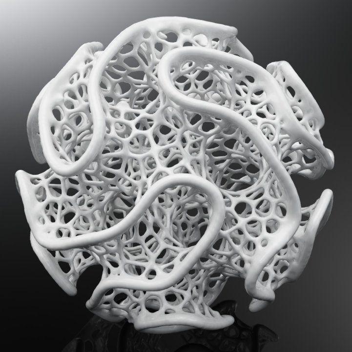 " If the task is great, it is so unreasonable how to step up, to divide into a dekilka of more other tasks, as simple as a viskonat. So and here - and for drawing our figurative 3D-elephant, it is necessary to make sprats of crocks.
Croc 1. Shared model
Actually, if you search your favorite model on the Internet, try to know the ready-made model. A lot of designers are interested in alternative versions, so you know - more printers are not big enough.
The name of the split-model is the cost of typing STL-files, prepared to each other in parts. Most of these models ideally go together one by one, and the deacons are rіzhutsya on shmatochki, to help them to friend. Qi files save your time, so that you do not happen to split the files on your own.
Before speech, before STL, online acquisition, modeled as STL warehouse. Files of this type are often necessary for a rich variety of rich components. Ale, you don’t care about winning them with other great models.
It is also possible to select different programs for the submodel. One of them is Slic3r. Open the warehouse STL in the program, press the button "Split" on the toolbar, and your warehouse STL will be divided into more files. Now you can cut the skin part according to your needs after you have decided or export the skin part from the small STL that looks like it is small, attached to the other.
Autodesk Meshmixer is just one more tool that you can hack for sub-storage STLs - everything you need to hack the "Separate Shells" command.
If the model you want to infringe is not available in folded form, you can split the STL file yourself. It is possible to work for the help of a general function, called a cut flat, as is available in most popular CAD programs.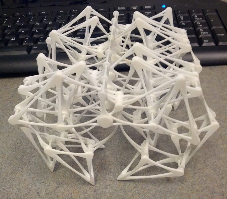
If you want a simple task, change your mind so that you have cut the model strategically correctly. First, change your mind, so that your rozrіz will lighten other models and you will not need support with a friend. And in a different way, try to know such a cut area for your model, so that the seam will not be so memorable and obvious, if the model is ready.
Krok 2. Locks and gates
Most of the main CAD programs allow you to create simple shapes for working with 3D objects. To ask for a bribe, you can model flanks, outlets and pits, or open in detail, so that you can help them get back, if the hour comes.
Another popular method of joining parts is to open the whole 2-millimeter one at your parts, and then insert a short piece of melted filament into it to catch the alignment before gluing.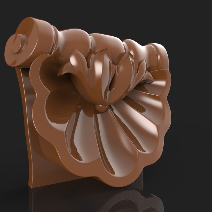
If you need a special construction, then you can try to beat traditional locks and keys, for example, from the galuzi of woodworking. You can use other materials, such as metal shears, screws or bolts for fastening parts, especially if you need more material. It may be necessary, as you create requisites or functional details.
Krok 3. Druk
Proceeding from krok, as you know Drukar, you yourself know the most. Mi tezh wrote a lot about the different aspects of 3D-druk in these articles.
Basic rules for using ABS plastic (part 1)
Basic rules for using ABS plastic (part 2): delamination
How to achieve clarity in 3D using the FDM method
The same goes for selecting materials. You yourself choose the optimal material, depending on your needs and possibilities. And we described the different powers of the filaments in the coming articles.
What is the difference between PLA, ABS and PETg?
Choice of plastic for 3D other company 3Dplast
Croc 4. Gluing
In fact, gluing can be part of the post-finishing process. That's why classical methods of post-processing are used for making details.
For example, the surface of the two ABS parts can be treated with acetone. Then the stench will begin to melt and for the melting of the upper ball can be eaten.
Either the surface with PET and PETg can be treated with dichloromethane or tetrahydrofuran, or with the method
Still, if you want more advanced methods of joining the components of a great object, it's more classic gluing. Most often it is either super-glue (as the object will not be functionally vicorist, but it is due to mucino trimming), or epoxy resin (as the object will be vicorist and become more attractive). Also, superglue is rotten for large areas of gluing - here it’s better to either take epoxy resin or melt the filament, from which the part was overworked. Ale epoxy resin will always be the best gluing option.
Post-fertilization of the finished viroba can be modified by different methods, as described here.
Free STL file Split flap display module・3D printer model to download・Cults
Moon base cryogenic tank
0,52 €
Moon Base - Hydrogen tank - Horton sphere
Free
Moon Base - Water Tank
Free
Moon Base - Ethanol towers
Free
Chiappa Rhino 50DS- the expanse Miller
Free
Moon Base - Chemical tower
Free
Fallout - Fusion Cell - Internet Monitor
Free
009 GN15 O-16.5 Model railway pier supports
Free
The best files for 3D printers in the Tools category
Universal spool holder
2.20 €
CNC remix Mostly Printed CNC
Free
Cutlery card
1. 92 €
92 €
Regular icosahedron Dome Connector interconnection
1,50 €
XXL Sledgehammer Holder (4.5kg/10lb) 033 I ENFORCE I for screws or peg board
Free
Tattoo ink holders
0,50 €
Arrow bookmark(only 15min)
Free
Tool Organizer
Free
Bestsellers in the Tools category
Ender 3 Briss fang Gen2, red lizard, spider, nf crazy, dragonfly, etc.
€1.86
Fire hydrant storage container
2.05 €
Quick print stackable parts containers / storage boxes
2.87 €
Armadillo - flexible wire conduit
€1.82 -twenty% 1. 45 €
45 €
INDICATOR FOR BETTER BED LEVELING FOR ENDER 3 V2
3.06 €
Printer boxes for Ikea Lack Table
1,99 €
Grinder | Grinder
€1.50
PRECISION CALIPER 3D PRINT DIY
3.04 €
Ender 3, 3 V2, 3 pro, 3 max, dual 40 mm axial fan hot end duct / fang. CR-10, Micro Swiss direct drive and bowden compatible. Printing does not require support
1.67 €
Tool holder for 3D printer V3.0
1.13 €
Ratchet holders - magnetic - holders for tool box organization
2.91 €
UNIVERSAL BED LEVELING INDICATOR FOR VERY ALL PRINTERS
3.06 €
BED LEVELING INDICATOR FOR ENDER 3 PRO
3.06 €
Quick print paint bottle holder (6 sizes)
2.