3D printing prevent stringing
Stringing or Oozing
Stringing or Oozing
Stringing (otherwise known as oozing, whiskers, or “hairy” prints) occurs when small strings of plastic are left behind on a 3D printed model. This is typically due to plastic oozing out of the nozzle while the extruder is moving to a new location. Thankfully, there are several settings within Simplify3D that can help with this issue. The most common setting that is used to combat excessive stringing is something that is known as retraction. If retraction is enabled, when the extruder is done printing one section of your model, the filament will be pulled backwards into the nozzle to act as a countermeasure against oozing. When it is time to begin printing again, the filament will be pushed back into the nozzle so that plastic once again begins extruding from the tip. To ensure retraction is enabled, click “Edit Process Settings” and click on the Extruder tab. Ensure that the retraction option is enabled for each of your extruders. In the sections below, we will discuss the important retraction settings as well as several other settings that can be used to combat stringing, such as the extruder temperature settings.
Common Solutions
Retraction distance
The most important retraction setting is the retraction distance. This determines how much plastic is pulled out of the nozzle. In general, the more plastic that is retracted from the nozzle, the less likely the nozzle is to ooze while moving. Most direct-drive extruders only require a retraction distance of 0.5-2.0mm, while some Bowden extruders may require a retraction distance as high as 15mm due to the longer distance between the extruder drive gear and the heated nozzle. If you encounter stringing with your prints, try increasing the retraction distance by 1mm and test again to see if the performance improves.
Retraction speed
The next retraction setting that you should check is the retraction speed. This determines how fast the filament is retracted from the nozzle. If you retract too slowly, the plastic will slowly ooze down through the nozzle and may start leaking before the extruder is done moving to its new destination. If you retract too quickly, the filament may separate from the hot plastic inside the nozzle, or the quick movement of the drive gear may even grind away pieces of your filament. There is usually a sweet spot somewhere between 1200-6000 mm/min (20-100 mm/s) where retraction performs best. Thankfully, Simplify3D has already provided many pre-configured profiles that can give you a starting point for what retraction speed works best, but the ideal value can vary depending on the material that you are using, so you may want to experiment to see if different speeds decrease the amount of stringing that you see.
Temperature is too high
Once you have checked your retraction settings, the next most common cause for excessive stringing is the extruder temperature. If the temperature is too high, the plastic inside the nozzle will become less viscous and will leak out of the nozzle much more easily. However, if the temperature is too low, the plastic will still be somewhat solid and will have difficulty extruding from the nozzle. If you feel you have the correct retraction settings, but you are still encountering these issues, try decreasing your extruder temperature by 5-10 degrees. This can have a significant impact on the final print quality. You can adjust these settings by clicking “Edit Process Settings” and selecting the Temperature tab. Select your extruder from the list on the left, and then double-click on the temperature setpoint you wish to edit.
Long movements over open spaces
As we discussed above, stringing occurs when the extruder is moving between two different locations, and during that move, plastic starts to ooze out of the nozzle. The length of this movement can have a large impact on how much oozing takes place. Short moves may be quick enough that the plastic does not have time to ooze out of the nozzle. However, long movements are much more likely to create strings. Thankfully, Simplify3D includes an extremely useful feature that can help minimize the length of these movements. The software is smart enough that it can automatically adjust the travel path to make sure that nozzle has a very short distance to travel over an open space. In fact, in many cases, the software may be able to find a travel path that avoids crossing an open space all together! This means that there is no possibility to create a string, because the nozzle will always be on top of the solid plastic and will never travel outside the part. To use this feature, click on the Advanced tab and enable the “Avoid crossing outline for travel movement” option.
Movement Speed
Finally, you may also find that increasing the movement speed of your machine can also reduce the amount of time that the extruder can ooze when moving between parts. You can verify what movement speeds your machine is using by clicking on the Speeds tab of your process settings. The X/Y Axis Movement Speed represents the side-to-side travel speed, and is frequently directly related to the amount of time your extruder spends moving over open air. If your machine can handle moving at higher speeds, you may find that increasing this settings can also reduce stringing between parts.
Related Topics
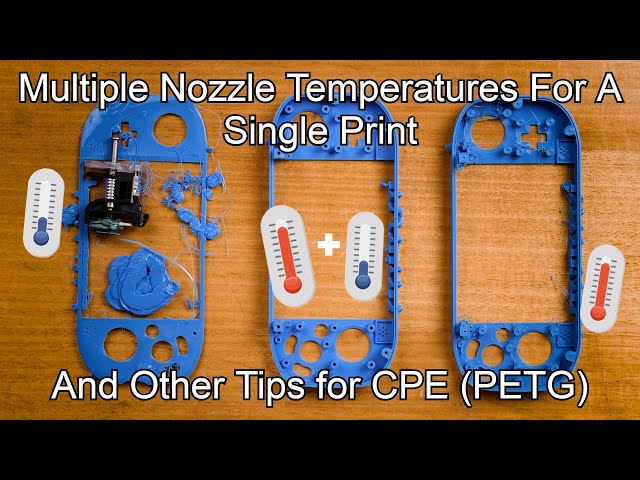
How to Avoid 3D Print Stringing: The Ultimate Guide
Printing with FDM technology might result in a number of defects due to incorrect mode, uneven quality of consumables, or some printer-related issues. We will consider the process of thread formation during nozzle movement, generally known as stringing or oozing.
What causes filament stringing?
When the nozzle is idly moving from one printing area to another within one layer, the melted filament may slightly leak and form a string between the start and end points of the route. The defect occurs most often with PETG printing, but it is possible with other materials as well.
The main causes of stringing are:
- incorrect retraction settings;
- excessive nozzle temperature;
- filament exposed to humidity;
- low print speed;
- external nozzle contamination;
- defective nozzle;
- large melt zone or a large diameter nozzle.

It might be hard to determine a specific cause from external signs, that is why it is better to consistently check and rule out all the possible reasons.
Major problems and their solutions
Humidity
Wet filament makes it drastically more difficult to adjust the print mode, and it is relatively easy to detect excessive humidity.
Extremely wet PETG. Characteristic features can be clearly seen: loose surface of the part, filament lint over the entire length of the threads.
It is widely believed that PLA, PETG, and ABS have little moisture absorption. Indeed, many users do not encounter problems with wet filament. At the same time, manufacturers offer drying modes for most of their consumables.
When printing with damp filament, there is usually an extraneous sound similar to hissing or crackling. The surface of the printout comes out matte and porous, and strings are formed over the non-print area.
Credit: maker. pro
pro
In this case, threads occur when water in the filament starts to boil, and the steam provides an excessive output of plastic. When these signs are recognized, drying is definitely necessary.
Incorrect feeding and temperature
Wet filament is a factor that can be detected separately, but the others are similar and should be dealt with sequentially. To begin with, it is necessary to make sure that the right amount of plastic is fed and the temperature regime is correct. Overextrusion manifests itself in oozing blobs, distorted geometry of the print, and ribbed horizontal surfaces.
Credit: prusa3d.com
And in this case, strings are formed when an excessive amount of plastic starts leaking from the nozzle during its idle movement.
There are special test patterns called "temperature towers" to check the temperature mode. These are a sequence of vertically positioned identical elements printed at different nozzle temperatures.
There is also a plugin for automated creation of test patterns in Cura, so let's see how it works. To install the plugin, you must create an Ultimaker account and log in to it. This will give access to the repository.
Install the Calibration Shapes plugin. After reloading the slicer, the Parts for calibration item appears in the Extensions menu.
To set up the PETG print temperature, select Add a PETG TempTower. The temperature tower model will appear on the screen. Now it is time for a post-processing script (a set of scripts will be installed with the plugin).
The settings in the screenshot above are set for a temperature tower with a range from 260 °C to 230 °C in increments of 5; the layer height is 0.2 mm.
For PETG, it might make sense to print a second tower with lower temperatures. For instance, it applies to PLA+. The settings are the same, only the starting temperature is 230 °C.
A tower allows visually selecting the correct print temperature. A temperature that is too high results in blobs, indistinct outlines, and a large number of strings. Lower temperatures lead to disruptions in feeding and poor mechanical strength of the part. Our towers in the photos show that evident stringing stops after 230 °C, and at 215 °C there are issues with feeding and layer adhesion. That is why 220 °C will be the optimum printing temperature for this particular filament on this particular machine. Therefore, set the appropriate value in the Printing Temperature field and make sure that the other temperatures are synchronized (they are dependent on the first value, but can be set manually).
Incorrect retraction
Retraction is used to prevent unwanted plastic leaking from the nozzle. This function will pull back the extruder before moving it over the non-print area. The basic settings for retraction in the slicer are length and speed. Insufficient length is a common cause of stringing. Excessive length leads to thread stretching, plastic getting into the cold zone, insufficient feed after moving the nozzle to the finish point, or plugging.
At too high a speed the thread will break in the melt zone or cause feed slippage. At too low — the thread will stretch without being pulled back inside the nozzle.
Terminal example: high print temperature with disabled retraction.
Typical values at which it is reasonable to start adjusting retraction are 30 mm/s speed, 1–2 mm length for a direct extruder, and 5–7 mm length for a Bowden. For instance, in Cura, retraction can be adjusted in the Travel section.
To check retraction, test patterns like "four square cones" are printed, but there are more functional tests to select retraction mode by analyzing a single printout. For example, this service generates a G-code with different retraction settings. It should be used with caution, because a large number of retracts per unit time occur during printing.
This service allows determining the optimal settings without having to reprint the test several times.
The default settings need to be adjusted for the printer in use. You can also reduce the number of vertical iterations — too high retraction makes no practical sense.
Appropriate settings for Kingroon KP3S with 0.4 mm nozzle, PETG.
The settings to attend to:
- X Dimension and Y Dimension.
- Nozzle Diameter.
- Filament Diameter.
- Start Temp — the optimal temperature for printing with the given material we have set in the previous step, or use the temperature recommended by the manufacturer.
- Extrusion Multiplier — the rate obtained by adjusting. At 1.0 there was a case of overextrusion, so here it is reduced to 0.97.
- Bed Temp.
- Number of Tests — we recommend to reduce it to 10, too high retraction speeds makes no practical sense.
- Travel Speed — idle speed, depends on the capabilities of the printer. Usually 80–150 mm/s.
- Custom Gcode — leave it as it is; if you need auto bed leveling before printing, delete ";".
- All other settings can be left by default.
The point of the test is as follows: the retraction length increases in increments of 0.5 mm along the perimeter, i.e. from 0.5 to 8 mm. The retraction speed increases with height, from 10 mm/s in increments of 5 mm/s.
The printout shows that when you increase the retraction length more than 1.5 mm, the quality of the protrusion does not change.
The photo shows the inadequate feed after retraction, which occurs when the length is too long and the speed is too high.
The final retraction length not only depends on the plastic and the type of extruder, it is also affected by a number of other parameters, such as the cooling efficiency of the hotend and design of the thermal barrier. Therefore, the settings for the same spool installed on different printers can vary significantly.
The printed test does not allow determining the exact retraction speed, so choose a standard value of 30 mm/s to avoid filament break and print at normal speed.
The "four cones" test, printed with the settings selected earlier. The retraction length is 1.5 mm, the speed is 30 mm/s. The printer is a Kingroon KP3S with the Titan direct extruder. Note that the printing of relatively large objects produces fewer strings than with "cones".
By comparison, the same test with PLA. No stringing already at a retraction length of 1 mm.
Different slicers have additional features designed to improve retraction performance and reduce stringing. For example, in Cura, it is Combing — moving to the next section not in a straight line, but over the already printed path.
Cura 4.11.0
If the Combing mode is on, stringing may be reduced. However, its use often leads to certain surface defects where it contacts with the nozzle.
Other factors
Worn or low-quality nozzles can also contribute to stringing. A normal nozzle has a thin channel in front of the outlet, but there are also nozzles that have virtually no channel. Practice shows that in the second case, the retraction works worse. Finally, it is reasonable to check that the nozzle is clean. The filament leftovers will drip and stick to the printout.
The inside of a quality nozzle.
Here, there is practically no output channel.
Speed also matters. It is more likely that the plastic will leak more at a low speed. The upper end is determined by the capabilities of the printer. On average, this value is in the 80–150 mm/s range.
Bottom line
To minimize stringing, you should first make sure that the filament is dry and that the temperature and feeding rate are correct. Only after that is it reasonable to proceed to the retraction settings adjustment. Specific length and speed will depend not only on the plastic, but also on the design of the extruder and the printer's hotend.
Techno Print 3D Company
This is our first review of the most popular and inexpensive 3D printers for 2020. The list will include the best-selling devices in two price ranges (up to 30 tr and up to 60 tr). Printers working with both plastic filament (FDM) and photopolymers (LCD/DLP) will be presented. This list will always be up to date, as it is periodically updated and supplemented. Read more→
The Chinese company Dazz3D announces the launch of the project on KickStarter and accepts pre-orders for Dazz3D Basic and Dazz3D Pro 3D printers. These revolutionary new devices are aimed at both the professional and amateur markets. Read more→
We all know that precise calibration of the 3D printer desktop is the foundation and the key to successful printing on any FDM printer. In this article we will talk about the main and most popular ways to level the "bed". So, as mentioned above, 3D printing without desktop calibration is impossible. We face this process Read more→
It's hard to go through a day today without hearing about 3D printing technology, which is bursting into our lives at an incredible speed. More and more people around the world are becoming addicted to 3D printing technology as it becomes more accessible and cheaper every day. Now almost anyone can afford to buy a 3D printer, and with the help of Read more→
The FormLabs Form 2 and Ultimaker 3 are perhaps the most popular 3D printers today, capable of high quality printing with incredible surface detail. Moreover, these two devices use completely different technologies, and therefore, there are a lot of differences between them. Many will say that it is wrong to compare them or Read more→
XYZprinting, best known for its daVinci line of desktop 3D printers, is bringing five new devices to the professional and industrial environment. One will use laser sintering technology, the second full color inkjet printing and three DLP machines. First of all, the novelties will be of interest to dentists and jewelers. Read more→
Cleaning the nozzle of a 3D printer is a fairly common process that any user of such a device has to deal with. This is not at all a complicated procedure that anyone can handle. You can complete this task in 15 minutes, using only handy tools and accessories. Read more→
Acetone steam polishing of ABS plastic is a process for smoothing the surface of 3D printed models. The result of this treatment makes your printed products look as if they were made by a professional mold casting method. If you want to understand how this is done correctly, then read this article. Aceto Read more→
3D Printing Support Structures - Complete Guide
An Easier Approach to Caliper Structures
Caliper Structures for 3D Printing - The Complete Guide
Everything you need to know about caliper structures used in 3D printing. Feel free to use overhangs and bridges in your models!
Caliper structures: If you have a lot of experience with FDM 3D printing (FDM - Fused Deposition Modeling), you may have found yourself in situations a couple of times in which you had to use such structures. An FDM 3D printer creates a 3D object by sequentially applying layers of thermoplastic materials. In this case, each new layer rests on the layer below it. If the model has an overhang that is not supported from below, it will likely sink or even fall off, and you will need to print additional support structures to ensure successful printing.
Caliper structures are seen as a necessary evil in 3D printing. On the one hand, they are absolutely necessary for models with dangerous overhangs or bridges. On the other hand, the cost of materials rises, finishing work is added, and there is a risk of damage to the surface of the model. Therefore, proper application of printed caliper structures is a very important aspect of 3D printing complex models.
Caliper structures in 3D printing: 3 easy steps to success
In this article, we will cover everything you need to know about support structures used in 3D printing. Detailed explanations are provided later in the text.
WHEN DO YOU NEED THEM?
In general, when a model has an unsupported overhang or bridge, caliper structures may be required to enable 3D printing. The figure below shows overhangs and bridges using the letters Y, H and T as an example.
A classic example of overhangs and bridges using the letters Y, H and T as examples.0003
Support structures are not required for all overhangs - 45 degree rule
Support structures are not required for all overhangs. As a general rule of thumb, if the overhang slopes less than 45 degrees from vertical, it can be printed without the use of caliper structures.
Support structures are required for overhangs greater than 45 degrees from vertical.
3D printers provide a slight (barely noticeable) horizontal displacement between successive layers, i.e., the applied layer is placed on the previous one with a slight displacement. This ensures that overhangs are printed that do not deviate too much from the vertical. Anything less than 45 degrees can be supported by previous layers, and anything above that number can't. A value of forty-five degrees is considered a break line.
This statement is best supported by the examples of the letters Y and T. The two slanted parts of the letter Y have an angle of less than 45 degrees with respect to the vertical. Therefore, if necessary, the letter Y can be printed without using any caliper structures performed by 3D printing.
For overhangs in the letter Y, printing of support structures is not required. But for overhangs in the letter T - yes. (source: 3DHubs online production platform)
On the other hand, the protruding parts of the T are at an angle of 90 degrees from vertical. Thus, in this case, for the 3D printing of the letter T, the use of support structures is a necessary condition, otherwise the result will be a nightmare (see the figure below).
Without caliper structures, it is not possible to print the letter T properly (source: 3DHubs online manufacturing platform)
2
Not all bridges need supports - the 5 mm rule.

As with overhangs, supports are not required for all bridges. A rule of thumb that has been proven in practice is that if the bridge length is less than 5 mm, the printer is able to print it without the need for a caliper structure.
This uses the 'bridging' printing method, in which the printer stretches the hot material over short distances and prints it with minimal sagging.
However, if the bridge length is greater than 5 mm, this method does not work. In this case, it is necessary to additionally print support structures.
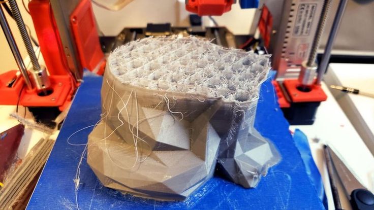
Bridges longer than 5 mm cannot be printed without support structures. Notice how they warp and deform.
TESTING PRINTER'S ABILITY TO PRINT OVERHANGS WITHOUT SUPPORT
The rule of thumb that if an overhang slopes less than 45 degrees from vertical, it can be printed without the use of support structures is just a rule of thumb. Much depends on the printer, its condition and the materials used. Printers that are in poor condition may not print 35 or 40 degree overhangs from vertical.
Before printing a model with overhangs, it is recommended that you evaluate the printer's ability to print small overhangs.
This is easy to do. Simply download the Massive Overhang Test print model from the Thingiverse website and print it. This model presents overhangs from 20 to 70 degrees in 5-degree increments.
Overhang print test model from Thingiverse website (Source: Thingiverse website)
Determine the angle at which the printer starts to print abnormally. This is the maximum overhang angle at which the printer can print without support. It is recommended to remember it for making further decisions on the need to use support structures.
DISADVANTAGES
Like many things in life, the use of support structures in 3D printing has certain weaknesses. There are several of them, so let's look at them.
1
Increased material costs
Support structures require additional materials. In this case, these designs after printing must be removed and thrown into waste.
When using 3D printing at the manufacturing level, the focus may be on the cost per model. If this is your hobby and you are limited in funds, then, for sure, this is also not indifferent to you.
3D printing of support structures means an obvious additional cost per model. Caliper structures require material that is subsequently removed and discarded, so any 3D caliper structures go to waste, which increases the cost of the printed product.
2
Print time increase
3D printing of support structures also increases print time as the printer prints additional volumes. It is quite obvious that the additional time spent depends on the number and height of the caliper structures.
3
Additional finishing
Additional finishing is required when printing support structures. (source: Formlabs)
3D printed support structures are not part of the model. They are used as a support for parts of the model during printing. This means that at the end of printing, there is an additional need to remove these structures before the model is ready for use.
In a production setting, extra work means additional costs for the model.
4
Risk of product damage
Left: Printing with supports. Middle: Removal of calipers with product damage. Right: Removal of calipers without significant damage to the product. (source: 3DHubs online manufacturing platform)
3D caliper structures come into contact with the walls of products and often stick to them. They are the only means of providing support under overhangs and bridges. If care is not taken when removing 3D caliper structures, defects may remain on the surface of the product. In the worst case, part of the model may break off along with the 3D support structure.
In general, there are significant drawbacks when using support structures. Therefore, here's another tried-and-tested rule: Minimize the use of 3D support structures and add them only when necessary . The following sections will explore the application of this principle, starting directly from the computer-aided design (CAD) stage and ending with printing.
GEOMETRY OF THE CALIPER STRUCTURE
Two types of support structures are commonly used: tree-like (“tree”) and linear / “accordion”.
Tree calipers
The tree caliper is a tree structure that serves as a support for the overhangs of the model. Calipers of this type only come into contact with the overhang at certain points.
3D caliper tree structures (source: Flashforge)
The advantage of using a 3D caliper tree structure is that it can be removed more easily without significant damage to the underside of the overhang. However, it should be noted that this type of caliper is only suitable for non-flat overhangs, such as the tip of the nose, toe or arch. For flat overhangs, it does not provide sufficient stability.
Linear support or "accordion"
This is the most commonly used type of support in 3D printing. It consists of vertical posts that are in contact with the overhang over the entire surface. This type of caliper is suitable for any overhangs and bridges. However, it is more difficult to remove without damaging the surface of the model.
Linear 3D support structures (source: Flashforge)0025
Tear-off 3D support structures
Single-extruder printers use tear-off support structures by default.
If you have one extruder, you have to use the same material to 3D print the support structures that is used to print the model. Of course, the density of the caliper structures can be adjusted to be much lower than the density of the model, but this is the only remedy that can be applied to the material of the caliper.
Since the model and 3D caliper structures are made from the same material, the only way to separate them is to either break off the caliper by hand or carefully cut it off with a knife.
These removal methods carry a high risk of damage to the model, and during removal, you must use the proper methods and be extremely vigilant and careful.
2
Dissolvable 3D calipers
Dissolvable calipers are easier to remove, but requires a printer with two extruders.
If you have a dual extruder printer, you have a better choice. You can load one extruder with PLA for model printing and the other with water soluble material such as PVA or limonene soluble material such as HIPS (polystyrene) for caliper structure printing. At the end of printing, it is enough to simply remove the support structure by washing off by immersing the model in water or limonene.
This removal method reduces the risk of model damage and simplifies finishing, making it ideal for complex prints.
HOW TO REMOVE 3D SUPPORT STRUCTURES
Because 3D calipers are difficult to remove and can damage the model, here are some tried and tested techniques for removing them properly.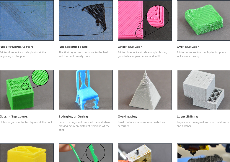
- First you need to determine which support structures are completely open and can be easily reached with your fingers. Try prying these calipers off with your fingers. Exercise caution. Extreme caution. If this operation is performed correctly, most caliper structures should come off without much effort.
- Then take a tool to remove 3D support structures that are difficult to reach. There are many opinions about which tools are best. You can use needle-nose pliers, a spatula, or a utility knife. You can also use all these tools together.
- When using a knife or scraper, it is a good idea to heat up the model or blade. This contributes to better delamination of the 3D support structures. A small butane torch will help, but care must be taken not to damage the model.
- Handle utility knives with care as they are very sharp.
- Sandpaper is also excellent for removal. When wet grinding with fine-grained sandpaper (from 220 to 1200), not only the removal of 3D caliper structures is performed, but also the model is polished.
 For best results, it is recommended to spray the part with water and sand in smooth, light strokes until the desired surface finish is obtained.
Wet sanding can be used to remove residual 3D caliper structures and smooth the surface of the model (Source: Formlabs) scratches and surface defects. Nail polish is great for partially or completely covering these marks.
If you are interested in how other users solve this problem, it is recommended to view the web page on the best ways to remove supports, calipers and filament structures - Best ways to remove foundations, caliper structures and other external filaments.
MINIMIZING 3D CALIPER STRUCTURES WITH SMART DESIGN
Integrating 3D caliper structures into the model
One way to avoid the use of caliper structures in 3D printing is to use additional elements in the model that perform a similar function. Sculptors have been using this technique for centuries.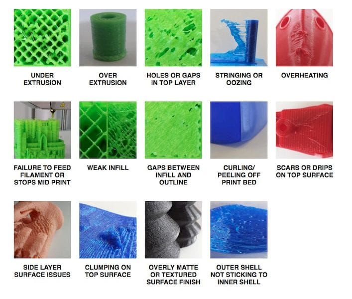 As an example, consider the sculpture "Venus the Conqueror" by Antonio Canova.
"Venus the Conqueror", sculptor Antonio Canova
Here the right arm is an overhang but rests on pillows. The left leg is another overhang, but here the folds of the toga serve as a support.
The next example is the Guardian model by @fantasygraph. As a support for the legs and buttocks of the model, he guessed to use a dress flowing in folds. The left hand rests on the spear lowered down.
@fantasygraph's Sentinel is a prime example of how support structures can be integrated into a model.
Integrating 3D support structures into a design is more art than science. It is necessary to find such elements that fit into the overall design and at the same time can be a support for overhangs or bridges. If done correctly, the model will be more beautiful and the printing process will be freed from unnecessary 3D caliper structures, which means saving time, money and labor.
Bevels
Another way to get rid of 3D support structures is to use bevels. With proper chamfering, dangerous overhangs can be turned into innocuous structures with angles less than 45 degrees.
For example, if you have a smoothly falling or folded edge, you can replace it with an edge with an angle that does not require supports. Such an angular pattern is called a bevel.
Left: Gradually rounded edge that requires supports. Right: A beveled edge that can be printed without 3D caliper structures (Source: Rigid Ink)
Similarly, if your model has a hole, you can turn it into a beveled teardrop hole. For the most part, this won't ruin the overall aesthetic of the model, but will help reduce the amount of 3D support structures needed to print the model.
Beveled hole (source: Markforged)
MINIMIZING 3D SUPPORT STRUCTURES BY REORIENTATION
. For example, it is much better to print the open box shown below with the open side up.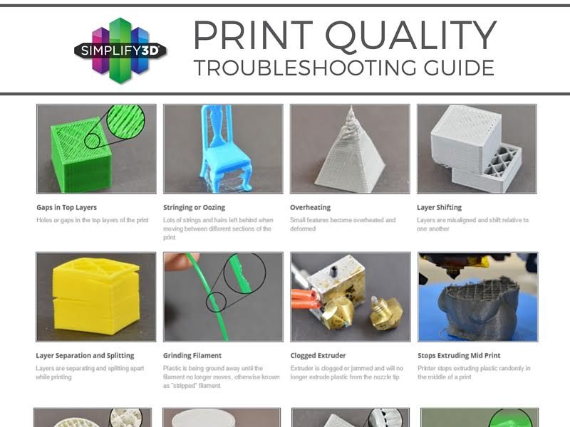
You can often minimize the use of 3D support structures by properly positioning the model on the build plate (source: Markforged)
Below is a more non-trivial example, again from designer @fantasygraph. This is a model of a man with a horizontally outstretched arm pointing forward and to infinity.
If you print the model as it is, you will need to support the left hand. And it, in fact, is a long overhang with an angle of 90 degrees.
Removing the supports will most likely leave imperfections on the underside of the arm. To avoid this, you can rotate the whole model by 45 degrees and simply add a support for its base. In any case, the quality of the basis of the model does not really matter. Thus, it is possible to print a model with fewer 3D caliper structures and save the left hand from damage.
A simple and ingenious solution. Maybe you can do it too?
PRINTING OVERHEADS AND BRIDGES WITHOUT 3D SUPPORT STRUCTURES
In the previous sections, attention was drawn to the fact that, if possible, you should try to use as little 3D support structures as possible. However, this means that it will often be possible to find yourself in a difficult situation in which the risk of model instability is inevitable. To minimize these risks, here are a few general tips.
- Make sure the 3D printer is in optimal condition.
- Cool the printed material as quickly as possible. The longer the material cools, the more likely it is that the bridge or overhang will warp or fall off. To do this, it is necessary to maximize the cooling capacity of the layers by cooling fans. Also, reduce the print temperature to the lowest possible.
- Reducing the print speed also speeds up cooling and is especially helpful when printing longer bridges and complex overhangs.
- It is recommended to print with the minimum layer thickness. Less layer thickness means less weight applied with each pass of the print head. In addition, it contributes to faster cooling of the material.
SUPPORT STRUCTURE SETTINGS IN THE CURA PROGRAM
Sometimes you simply cannot do without 3D support structures. But even in this case, every effort must be made to ensure the stability of the 3D support structures, so that they do not consume a lot of material, they are easily removed and do not damage the surface of the model.
The layering manager has many additional functions for fine-tuning support structures. Most layering programs can automatically create calipers, but they also have a manual mode that lets you add or remove calipers anywhere. In addition, the layering manager has many different settings to control the following aspects of the caliper structures.
- Location of 3D supports
- Strength of 3D supports
- Easy removal after printing
- Damage to the printed surface
In this article, we decided to focus on Cura, one of the most popular free layering software.
Cura has a number of settings related to support structures located in the Support section of the Custom Settings menu. With the correct setting of these settings, you can create 3D support structures that meet most of the basic requirements.
1
Enable automatic creation of 3D support structures for unstable models
Let's start from the beginning. How can I check if a model needs additional supports?
Cura makes this easy. Immediately after importing the model into Cura and placing it on the virtual working base, you should pay attention to the areas colored in red. These are the areas where Cura found instability. It should be noted that, possibly, areas without supports will not be visible until the camera is rotated.
If the bottom of the part is painted red where the model touches the work base, there is no need to worry that there is no support under this area. This problem will be solved by a working base. Small red areas at the top of holes or between two structures are called bridges and Cura will process them automatically.
You should start to worry if there are other parts highlighted in red. First you need to activate the automatic creation of support structures in order to ensure that these red areas are successfully printed.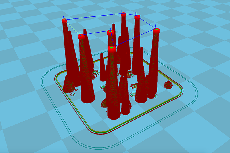 To do this, just check the Generate Support checkbox in the Support section.
So, the function of automatic creation of support structures is activated, but no external changes to the model occur. The reason is that Cura does not show support structures in the default Solid view. To view the generated 3D support structures, you must change the view mode to Layer View (View layers). The material of the calipers (lines and volume) will be displayed in turquoise. You need to move the layer slider up and down to see where the support is added to the model.
2
Tree support or linear support selection
Support tree structures in Cura
Cura creates 3D linear support structures by default. Version 3.2 beta of Cura provides the option to use tree supports instead of the default linear ones.
3
3D support structure positioning control
Two types of support structure positioning in Cura: Everywhere and Touching Build plate
When you activate the option to create support structures, the Placement item automatically appears in the Support section. The Placement option provides the ability to control the approximate location of support structures. There are two options: Everywhere and Touching Build plate. The Everywhere option is selected by default.
When the Everywhere option is selected, Cura 3D attempts to create support structures where they are needed. This means that not only 3D caliper structures will be created that will be placed on the working base, but also caliper structures that will be based on the details of the model. This is the rational choice for most cases, as it guarantees the necessary support for all unstable areas.
However, if you select the Everywhere option for very complex models, the model may be completely covered with the material used for the calipers. If there is no such intention, you just need to set the Touching Build plate option in the Placement settings. This option will create 3D caliper structures under the hanging parts of the model only between the working base and the model.
4
The Enable Support Roof option can improve the surface finish of the overhangs, but will incur some additional cost.
Since the overhang of the model is always printed on top of the 3D caliper structures, the optimal surface finish of the parts is not always guaranteed. And in this case, the hidden setting Enable Support Roof can help.
The arch of the support is a dense layer in the upper part of the caliper structure, which does not detract too much from the quality of the surface of the overhangs. When this option is activated in the Cura 3D program, by checking the appropriate box, a better quality finish is obtained. But this improvement comes at a cost, as removing the caliper structures becomes more difficult than usual when choosing this option. This option is only recommended if the surface quality of the overhang is important to the finished part itself.
5
Prevent 3D support structures from damaging the outer walls of the model by using the Support X/Y Distance setting
Sometimes 3D support structures are too close to the outer wall and leave traces on the outer surface of the model. This can be avoided by using the hidden Support X/Y Distance setting in the Support section.
In Cura, the Support X/Y Distance setting generally controls the minimum allowable distance between the model's vertical walls and the support structure in the X-Y plane. If the 3D support structure damages or sticks to the walls, you can increase this value in 0.2 mm increments until the walls are smooth. However, it is highly recommended to ensure that there are no small overhangs protruding from the outer walls, which would be left unsupported by leaving a small distance between the support and the walls. With these small overhangs, you may even need to decrease the X/Y distance instead of increasing it. Otherwise, printing will fail.
6
Z Distance setting to allow easier removal of 3D support structures model layers. The Cura program creates this weaker connection by leaving a certain space between the top and bottom of the support structure and the model - this space is known as the Z distance.
By setting the hidden Z-Distance settings in the Support section, the 3D support structures can be more easily separated from the model. The default value of this setting is equal to the height of the layer. So if the layer height is 0.1mm, the default Z distance will also be 0.1mm.
If the support material is difficult to separate from the model, it is recommended to increase this value in increments of layer height until it separates cleanly. Cura may or may not provide additional support for any particular layer. Unfortunately, half layer values do not exist. That is, if the Z Distance value of 0.2 mm is too large for printing with a layer height of 0.1 mm, and the Z-Distance value of 0.1 mm is not enough, there are no other options for setting the Z Distance value.
7
Selecting the right 3D caliper structure to strike the right balance between strength and ease of removal
Support patterns in Cura
Cura provides one of seven 3D caliper patterns.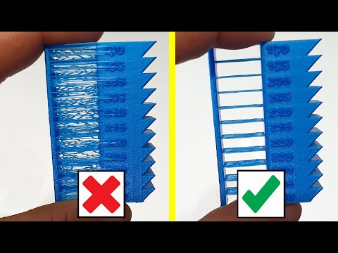 The pattern can be changed using a hidden setting called Support Pattern in the Setting section.
In most cases, the default pattern, Zig Zag, provides the best balance between strength and ease of removal. Other scheme options: Triangles (Triangles), Lines (Lines), Grid (Lattice), Concentric (Concentric), Concentric 3D (Concentric 3D) and Cross (Cross). If the default schema doesn't work, you can experiment with other options. Each provides a different balance between strength and ease of removal.
Caliper structures are a necessary evil in 3D printing. They are needed to print complex overhangs and bridges on the model. But when soluble 3D support structures cannot be used, it is recommended to try to minimize their use. We've covered situations where 3D caliper structures aren't needed and mentioned a few creative tricks for printing without them.
However, often the overhang or bridge may be such that a support structure has to be used. In this case, you need to change the layering settings so as not to waste too much material and not damage the model during the removal of supports.