3D printing offset
What it is and how to adjust it
Adjustment of the 3D printer’s Z offset is a way to achieve successful prints in a variety of situations, such as when using filament with poor adhesion or when using a thick build surface.
This article goes over the basics of Z offset, discussing the meaning of the term, the reasons why users might need to incorporate a Z offset, and looking at how to adjust this key parameter in three different ways: using G-code, slicing software, and a 3D printer’s physical LCD display.
A Z offset is a user-defined print setting that allows the printhead to be positioned above or below the default Z home position (true zero point).
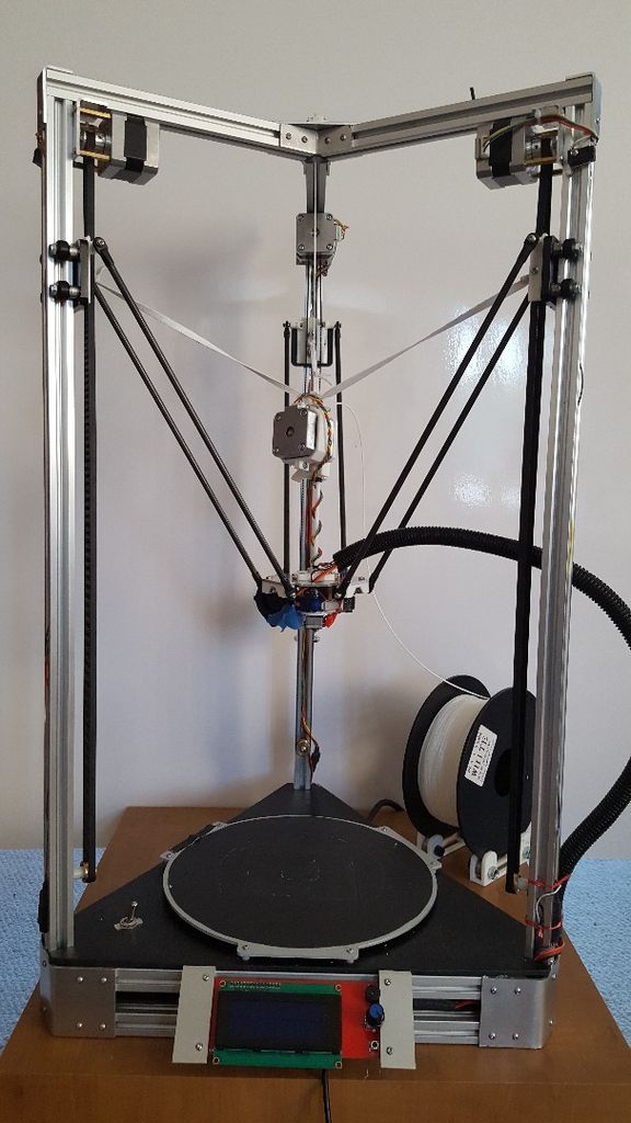
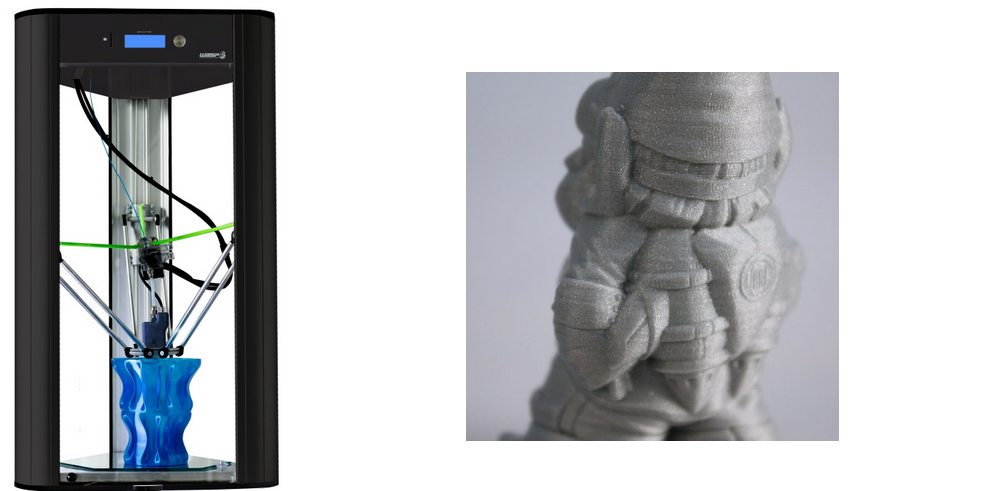
A standard Cartesian-style FDM 3D printer has a printhead that moves along three axes. Movement along the X and Y axes allows the printhead to “draw” each 2D layer, while movement along the Z axis allows the printhead to move upwards to the next layer.
Because a 3D printer has a fixed build volume, there are limits to how far the printhead can move along any of these three axes. And to prevent the printer from trying to exceed these limits, hardware manufacturers install small sensors called limit switches (or endstops) which detect when a moving part has reached its limit and cannot move any further.
The limit switch on the Z axis is important because it effectively prevents the printhead from burrowing into the build surface, which could potentially cause damage to the print bed and the hotend. The limit switch recognizes when the printhead is at its lowest possible point, and prevents it from descending further. The Z probe on a printer with automatic bed leveling performs the same function.
The “home position” of the printhead more-or-less corresponds to the position where these limit switches kick in. So when a printer is “homed,” the printhead sits in a corner of the print bed, just fractionally above the surface. But sometimes a user might want the printhead’s default starting position to be slightly higher or lower on the Z axis.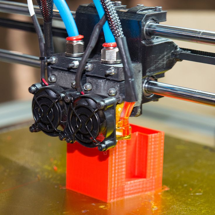 This can be achieved by introducing a Z offset, and there are several reasons why a user might do this.
It is important to understand that adjustment of the Z offset is not an essential form of calibration like bed leveling. Bed leveling, which should be performed when a 3D printer is set up or when a new component has been installed, ensures the nozzle is the correct distance from the print bed at every point across the build surface. It is a necessary procedure for preventing print failure.
By contrast, adjusting the Z offset is a secondary step that users may wish to perform in order to accommodate changes to material type or build surface, or simply to achieve a better first layer. Reasons for adjusting the Z offset include:
First layer: Setting a Z offset can help achieve a good first layer that is neither too far from the build plate (which can lead to adhesion issues[1]) nor too close (which can lead to extrusion issues).
Compensating for change in build surface: If changes are made to the build surface — adding a PEI sheet on top of the bed, for example — then the printhead may need to be repositioned so it does not sit too close to the new surface.
Catering to a different material: Some filaments (PLA, for instance) work best when slightly squashed down onto the build surface in order to improve adhesion; others (like PETG) respond better when deposited from a greater height.
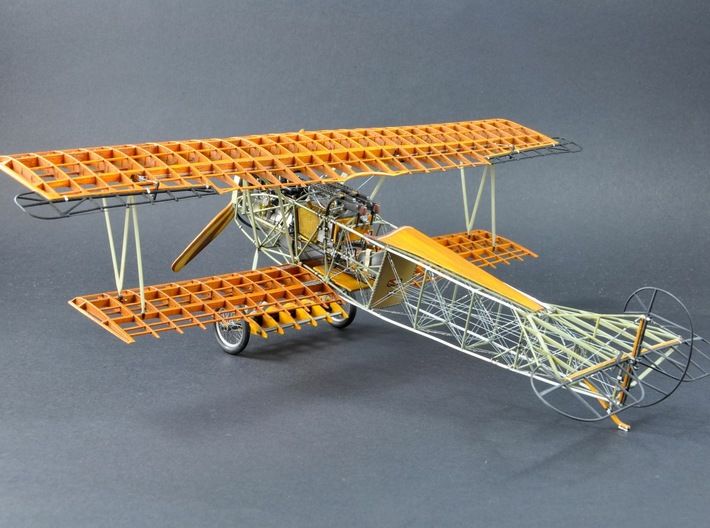
Printing onto a substrate: It is possible to print directly onto another object rather than onto the print bed. An easy way to do this is to adjust the Z offset to compensate for the thickness of the substrate.
Printing onto a thick glass build surface may require a positive Z offset
Before making adjustments, users should level their print bed, either using their printer’s auto bed leveling function or by manual adjustment of bed leveling knobs.
Auto bed leveling (ABL), a feature that is becoming more common on FDM printers, involves the use of a component called a Z probe. This probe measures the gap between the print bed at nozzle tip at different points on the bed. If the distance is equal at all points, the bed is level; if the gaps differ between points, it is not. Confusingly, ABL doesn’t actually involve a physical leveling of the bed. Rather, it instructs the printhead to compensate for any unevenness by adjusting its height at different points.
Manual bed leveling, on the other hand, does involve physically leveling (or tramming) the bed. The most common method is to use a piece of paper sandwiched between the nozzle and the build surface; when pulled, the paper should offer slight resistance. If there is no friction, the nozzle is too far from the bed, but if the paper offers too much resistance or gets stuck, it is too close. This exercise should be repeated at different points across the bed, with the bed leveling knobs used to make incremental adjustments.
One way to adjust Z offset when 3D printing is to use G-code. However, beginners may prefer to use the more intuitive Z offset settings in their slicer or on their printer’s LCD display.
The relevant G-code commands for adjusting Z offset are G0 (move) and G92 (set position). To add a 0.1 mm Z offset (i.e. to increase the space between bed and nozzle tip by 0.1 mm), input the following commands:
G0 Z0 (This instructs the printhead to move to the zero point on the Z axis.)
G92 Z-0.1 (This instructs the printer to interpret its current position as though it is 0.1 mm lower. So, logically, the next time G0 Z0 is input, the printhead will position itself 0.1 mm higher than it did the first time.)
An alternative way of achieving the same effect would be to input the following commands:
G0 Z0.1 (This instructs the printhead to move 0.
 1 mm above the zero point.)
G92 Z0 (This instructs the printer to treat its current position — 0.1 mm higher than the original zero point — as the new zero point.)
Note that to add a negative offset — i.e. to decrease the space between nozzle and bed — then any positive values in the above examples should become negative ones, and any negative values should become positive ones. For example, inputting the commands G0 Z0 and G92 Z0.1 will position the nozzle tip 0.1 mm closer to the bed.[2]
A slightly easier way to adjust the Z offset is to change the settings in your slicing software. The outcome is the same, as the slicer is effectively just changing the G-code, but the interface of the slicer may be more user-friendly, especially for beginners.
Setting a negative value will position the printhead closer to the build surface than true zero, while setting a positive value will move it further away from the build surface.
Simplify3D
To adjust Z offset in Simplify3D, find the “G-Code” tab under “Edit Process Settings.” The “Z-Axis Offset” setting can be found in the “Global G-Code Offsets” section, along with offsets for the other two axes. The Z offset is defined in millimeters.
Cura
To adjust Z offset in Ultimaker Cura, a Z offset plugin like this one is required. Once the plugin is installed, search “Z Offset” in the settings search bar (under the “Profile” drop-down box) to bring up the parameters. The Z offset value is defined in millimeters.
Slic3r
To adjust Z offset in Slic3r, navigate to “Printer Settings” (not “Print Settings”). Z offset, defined in millimeters, can be found in the “Size and coordinates” section at the top of the page.
All 3D printers running Marlin firmware (including the Creality Ender 3) allow for adjustment of Z offset using the printer’s LCD display.
On the display, navigate to the “Control” section. Within that section, find the “Motion” settings. Z Offset is the first parameter in this group of settings.
Finding the ideal Z height for a print can take time, but adjusting Z offset is a relatively simple procedure that users should exploit in order to accommodate new build surfaces and new materials, or when troubleshooting issues with the first layer. The easiest way to add a Z offset is to adjust settings within the slicer, but more experienced users may prefer to use G-code commands.
[1] Singh A, Yadav PK, Singh K, Bhaskar J, Kumar A. Design of 3D Printed Fabric for Fashion and Functional Applications. InAdvances in Manufacturing and Industrial Engineering 2021 (pp. 729-735). Springer, Singapore.
[2] RepRap contributors. G-code [Internet]. RepRap. 2022 [cited
2022 May 27]. Available from: https://reprap.org/mediawiki/index.php?title=G-code&oldid=189591
3D Printer Z-Offset: What It Is and How to Use It
3D Insider is ad supported and earns money from clicks, commissions from sales, and other ways.
The Z-offset setting of your 3D printer is the distance between the Z home position and the hot end. Calibrating this setting is a key element of attaining the perfect first layer. The Z-offset can also be manipulated to add extra print bed material or to a model on top of another.
The Z-offset of your 3D printer is only one of more than a dozen settings you will need to fiddle with on a filament-based printer. It is also one of the more important ones, especially if you’re trying to make your prints as close to perfect as possible. Check out this primer on what the Z-offset is and how you can use the setting to your advantage.
What is the Z-offset?
Simply put, the Z-offset is the distance between the nozzle and the print bed when the build plate is at the Z home position or when the Z-axis limit is triggered. Setting a Z-offset value protects the build plate from damage, while also ensuring that the first layer of a project is printed correctly.
There is an optimal Z-offset setting that will result in a perfect first layer. If the nozzle is too high, the filament might not stick to the bed. If the nozzle is too low, it may result in under-extrusion issues or even cause damage to the print bed. At just the right level, there is just enough pressure on the filament to make it stick to the bed.
The ability to adjust the Z-offset of a 3D printer can also come in handy if you’re adding another material on top of your standard print bed, such as a glass bed or a magnetic PEI plate. It is also possible to start printing on an object atop the print bed or continue a project that had to be paused mid-print.
How to calibrate the Z-offset
Calibrating the Z-offset of your 3D printer is something that you will need to learn eventually. It is absolutely necessary whenever you manipulate the print bed in any way, or even as part of regular maintenance. Depending on the brand and model of your 3D printer, there may be several calibration methods available to you. In this section, we will be running through all these methods.
One requirement that applies to all these methods is that you have to heat the build plate first before calibration. Regardless of the material of your build plate, it will expand upon heating. By calibrating with a hot plate, you will be working with a more accurate simulation of the actual operating conditions of the 3D printer. If you work with different types of filament, just heat the print bed to the highest temperature that you will need.
With that aside, we can start discussing the Z-offset calibration methods.
Manual calibration
Some printers have physical limit switches located along the axes that prevent damage to the print bed by limiting its movement. These are screwed onto the axes and can be moved up and down as necessary. This is an option if you can locate the limit switches on your 3D printer. Do not attempt to do this if you don’t know what you’re doing.
Manual calibration by the movement of the limit switch isn’t the appropriate method if you want to make small and precise adjustments to improve the quality of your first layer.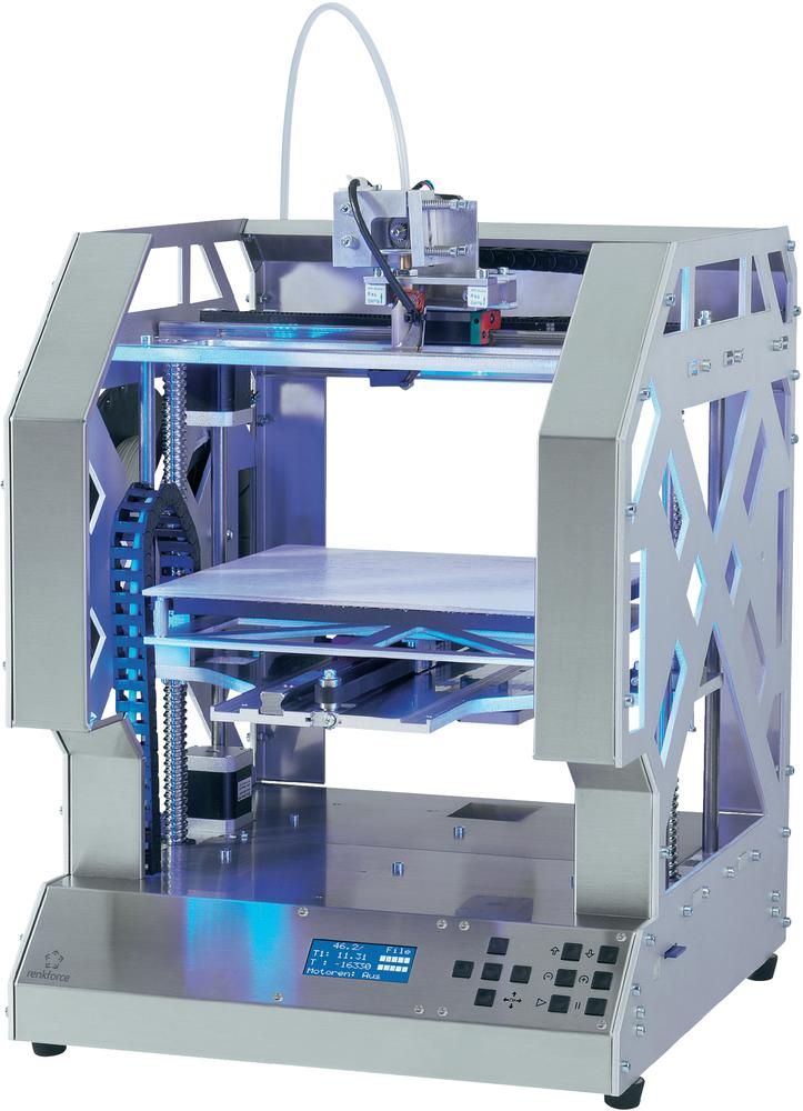 However, it’s a good option to give your print bed more room for later adjustments.
G-Code calibration
If you can edit the G-Code of your 3D printer, you can do this to shift the printer’s entire z-axis. This effectively changes the Z home position of the print bed.
To do this, start by executing the following commands:
- G28 Z0
- G92 Z0.1
In this sequence, the G28 command moves the printhead to the default home position. The G92 command then assigns the value of 0.1 mm. to the printhead’s current position, thereby also shifting the home location downward by a value of 0.1 mm. If you want to shift the home location upward by 0.1 mm, adjust the parameter of the G92 command to the negative value (G92 Z-0.1).
Slicer settings
If you’re using a slicer like Cura, then you can adjust the Z-offset quite easily through the slicer settings. This method currently only applies to the beta of version 5.0. To start, you will need to go to the Marketplace, and download and install the “Z Offset Setting” plugin.
Once installed, just head over to the print settings and the Build Plate Adhesion section. Here, you should already see the “Z Offset” setting with the option to input a value in millimeters. This method makes it a lot easier to experiment with Z-offset settings until you find the setup that works perfectly for your 3D printer.
Calibrating from the printer display
Some of the more advanced 3D printers that run on Marlin firmware even let you change the Z-offset settings directly from the printer’s display panel. The Ender 3 and Ender Pro are just two examples of 3D printers with such features.
The exact location of the Z-offset option may vary depending on which version of Marlin your printer is running, but it should not be hard to find. Adjusting the Z-offset here is even easier than doing it in your slicer, and also lets you experiment with different settings.
Print an endstop
It may seem like a rudimentary solution, but you can place a physical end stop on the Z-axis to adjust the Z-offset. There are several 3D printable models of these end stops. Good examples include this end stop for the Creality Ender 3 and another one for the ANET A8. These replace the standard limit switch that can be found in these printers.
There are slight variations in the various end stops available out there, but they all have similar objectives – adjustment of the Z-offset by simple knob adjustment. This makes it possible to make precise Z-offset adjustments, even just by visual approximation. Those who are more experienced in working with their 3D printers and are very familiar with their performance will likely have fun playing around with this contraption.
No matter which method you go for, getting the Z-offset just right will always involve a healthy amount of trial and error.
Final thoughts
It’s often said that getting the perfect first layer is the key to making a perfect 3D print. A lot of work goes into this first layer – getting the Z-offset value just right is an essential part of that process.
Warning; 3D printers should never be left unattended. They can pose a firesafety hazard.
3D Printing Technologies - Antar Printing House in Khabarovsk
Automated production of three-dimensional figures based on their computer model was implemented quite a long time ago, back in the last century. After all, CNC milling or turning machines to some extent solved this problem. But 3D printing is considered a breakthrough in the technology of creating objects based on a virtual three-dimensional image. It is based on a completely different principle, when an object is formed not by processing the original workpiece, but by recreating it layer by layer in various ways.
This technology appeared quite a long time ago, in the 80s, and is now used almost everywhere. This is due to its significant reduction in price. If the first 3D printers were built tens and hundreds of thousands of dollars, now they have reached the level of almost household devices available to any consumer.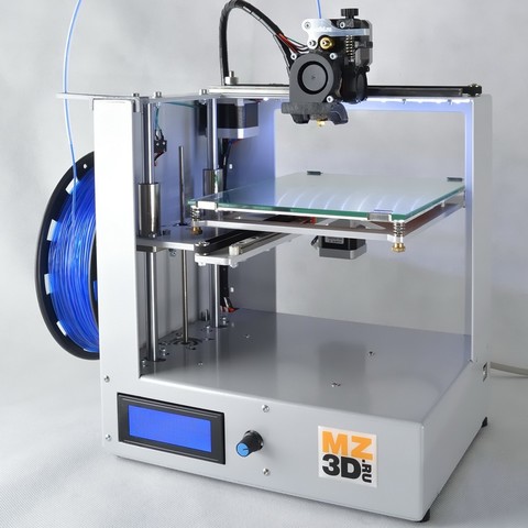
The history of 3D printing. Stereolithography
The study of this direction in technology began with the research of the American Charles Hull, who got excited about the idea of creating three-dimensional figures back in the late 40s. A method that he was able to patent only at 1986, was called stereolithography, and it was based on the process of creating objects using the photopolymerization of a liquid substance. The first industrial 3D printer was called that - a stereolithographic installation. This technology involved "growing" an object by superimposing layers of fractions of a millimeter on a continuously moving platform. The units produced by the Hull-founded 3D System were commercially successful, but limited in demand due to their considerable cost and bulkiness.
Modern 3D printing technologies
And only in the current century, around 2012, did a breakthrough occur in the 3D printer market, when compact and cheap consumer-grade models appeared.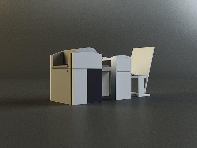 Buying them now is no problem, you can even order in the online store. The aforementioned 3D System company also started their production, but its printing technology is far from the only one.
LOM - sheet printing
Back in 1985, another method was proposed - by forming objects from thin sheets, connected using a heated press. It was invented by Mikhailo Feigen, and not only plastic, but also paper was used as a material. The three-dimensional models of the earth's surface created with its help look very impressive. However, this method, referred to as LOM, has some disadvantages associated with insufficient strength of the resulting sample.
SLS - powder plus laser
Around the same time, in 1986, a more advanced technology appeared that uses a laser and powder as a raw material. The principle of operation lies in its layer-by-layer sintering by a laser beam along a given contour in a special chamber. Accordingly, this technology is designated SLS, that is, selective laser sintering.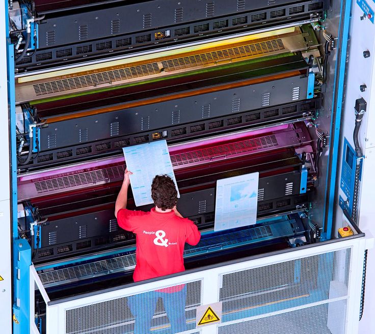 The powder used can be made from polymers, ceramics, metal or foundry wax.
The advantage of this method, proposed by Carl Descartes, can be considered not only the use of various materials, but the possibility of simultaneous production of several items. The disadvantages include the porous structure of the obtained samples, as well as the need for regular cleaning of the chamber.
SGS - UV Curing
This method was developed by Gubital in Israel a year later. In it, as in stereolithography, photopolymerization is used, however, the technological process itself involves the preliminary formation of a template that covers a thin layer of photopolymer. After its exposure to ultraviolet irradiation, the material solidifies selectively (only under the template), the process is repeated cyclically.
The advantage of this technology is the possibility of stopping it, for example, to check the quality of workmanship. The disadvantage is the use of unique high cost polymers. The installation itself also costs a lot - hundreds of thousands of dollars. For this reason, 3D printers of this class have not received distribution in our country.
FDM - Filament Printing
In the early 90s, this technology made a splash in the market when Stratasys offered consumers $50,000 3D printers. Inventor Scott Crump received a patent for it at 1988, and the installation itself is somewhat similar to a conventional inkjet printer. After all, it uses a real print head, through which the melt of plastic, metal or wax (in the initial state - in the form of a thread) flows down and forms an object in even layers. The transition to the next layer is carried out after lowering the platform on which the sample is located.
Currently, all of the above methods are used for 3D printing, however, the invention of Charles Hull is considered the most promising. This is due to the fact that stereolithography has significantly less restrictions on the materials used.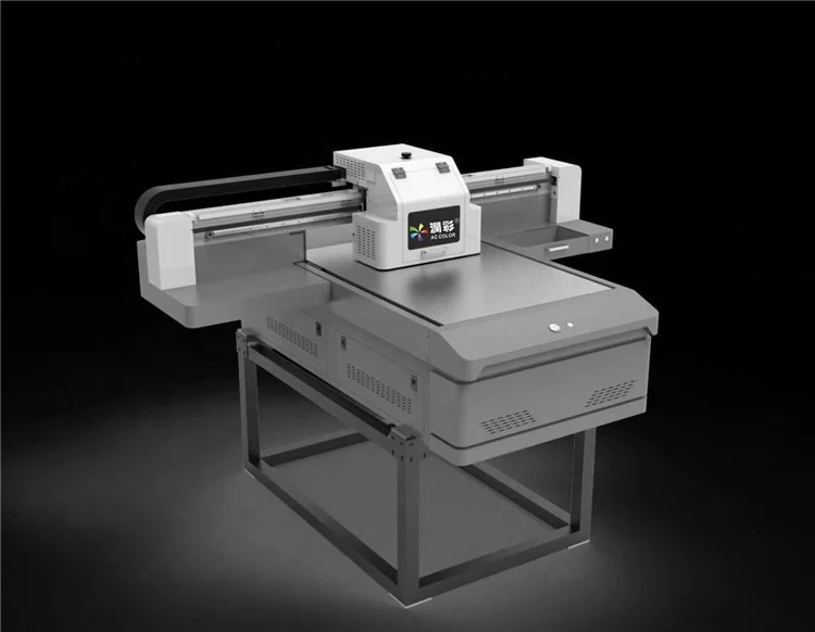 Regardless of the method used, the most important factor in the development of this technology is its penetration into various spheres of human activity. Today, they are not limited to industry, and 3D printing is confidently taking its place in construction, medicine, and even culinary.
We can safely say that this is technology of the XXI century .
3D Systems 660 Projet Four color offset press Used equipment
- Description
- Detailed information
- About this seller
The ProJet CJP 660Pro is the simplest and most efficient large format full color 3D printer in its class. It is fast, accurate, high resolution, and uses environmentally friendly, non-hazardous materials with no liquid waste. Ideal for architects, consumer product design and development, education, medical models, stop-motion animation, professional model shops, fine art production and more.
Photorealistic color
The ProJet CJP 660Pro includes professional 4-channel full color CMYK 3D printing to create stunningly beautiful, full spectrum photorealistic models to better appreciate your design intent in your specified colors. Multiple printheads provide the best range of accurate and consistent colors, including gradients.
High throughput
With print speeds 5 to 10 times faster than all other technologies, you can create large or multiple models at the same time in hours. Boost productivity with stacking and nesting options, and select Draft (Monochrome) to print up to 35% faster.
Low cost per part
Based on reliable and affordable CJP technology, the ProJet CJP 660Pro prints parts 7 times cheaper than other technologies.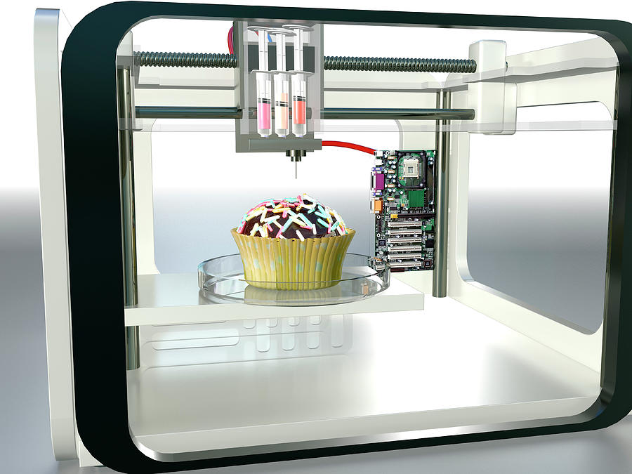 Through efficient use of material, you will eliminate waste and reduce finishing time as no supports are required and unused base material is recycled.
APPS:
Concept Modeling
Communication, Sales & Marketing Models
Rapid Design Iteration
Display / Art Models
Simulation Models
Surgical Practice
FEM Analysis
Assembly Visualization
Ergonomics
Color and Texture Check
FEATURES:
Color Inkjet Technology
Full color CMYK printing
High resolution and great features
Use of natural building materials
Convenient integrated parts cleaning station
Efficient, safe and easy infiltration of models with the optional pull-down workbench
BENEFITS:
Unique professional CMYK full color quality
High print speed
Low operating costs
Safe and environmentally friendly
Easy post-processing without deletion support
Select one of the options for finishing parts according to your requirements.
This description can be translated automatically. Please contact us for more information. The information in this announcement is for guidance only. Exapro recommends that you check with the seller before buying a machine.
| ------------------- | |
| Operating hours | |
| On hours | |
| Condition | good condition |
| CE marked | --------- |
| Status | |
| Data sheet | 3D Systems Projet 660 Pro |
| Client type | Consultant |
| Active with | 2021 |
| Online offers | 4723 |
| Last activity | November 24, 2022 |
Description
The ProJet CJP 660Pro is the simplest and most efficient large format full color 3D printer in its class.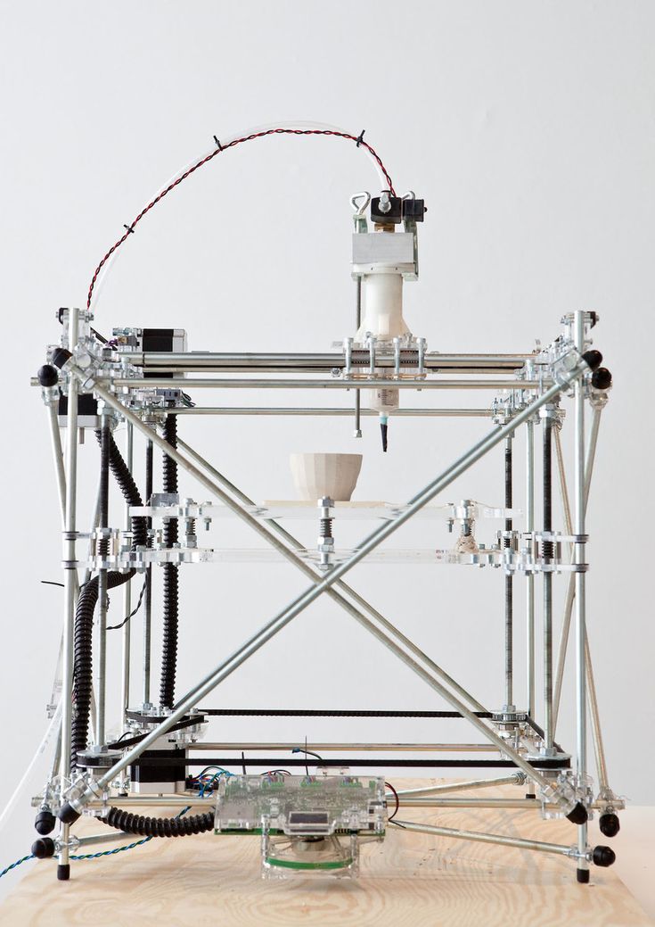 It is fast, accurate, high resolution, and uses environmentally friendly, non-hazardous materials with no liquid waste. Ideal for architects, consumer product design and development, education, medical models, stop-motion animation, professional model shops, fine art production and more.
Photorealistic color
The ProJet CJP 660Pro includes professional 4-channel full color CMYK 3D printing to create stunningly beautiful, full spectrum photorealistic models to better appreciate your design intent in your specified colors. Multiple printheads provide the best range of accurate and consistent colors, including gradients.
High throughput
With print speeds 5 to 10 times faster than all other technologies, you can create large or multiple models at the same time in hours. Boost productivity with stacking and nesting options, and select Draft (Monochrome) to print up to 35% faster.
Low cost per part
Based on reliable and affordable CJP technology, the ProJet CJP 660Pro prints parts 7 times cheaper than other technologies. Through efficient use of material, you will eliminate waste and reduce finishing time as no supports are required and unused base material is recycled.
APPS:
Concept Modeling
Communication, Sales & Marketing Models
Rapid Design Iteration
Display / Art Models
Simulation Models
Surgical Practice
FEM Analysis
Assembly Visualization
Ergonomics
Color and Texture Check
FEATURES:
Color Inkjet Technology
Full color CMYK printing
High resolution and great features
Use of natural building materials
Convenient integrated parts cleaning station
Efficient, safe and easy infiltration of models with the optional pull-down workbench
BENEFITS:
Unique professional CMYK full color quality
High print speed
Low operating costs
Safe and environmentally friendly
Easy post-processing without deletion support
Select one of the options for finishing parts according to your requirements.