3D printing model buildings
Guide to 3D Printing Architectural Models
Despite a move from the drawing board to digital screens, physical architectural models still play a significant role in helping architects visualize blueprints.
3D printing technologies help bridge the gap between digital and physical worlds and empower architects and model makers to create high-precision architectural models quickly and cost-effectively directly from digital drawings.
This guide provides comprehensive information about using 3D printing to produce architectural models, the different 3D printing processes for architecture, and the workflow for creating 3D printed models from architectural computer-aided design (CAD) software.
White Paper
This white paper covers how to make smart modeling decisions, from choosing scale to designing for assembly to post-processing, and how to use these strategies in common software ecosystems.
Download the White Paper
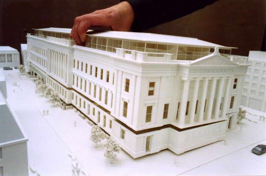
Since the age of the Pharaohs, architectural models have served as physical representations during structures’ development to help sell a project, support fundraising efforts, and solve construction challenges.
Traditionally, model-making is a manual craft that involves working with materials such as wood, ceramic, cardboard, or clay, which can be extremely time-consuming and repetitive. Architecture studios and practices today have access to a wider range of tools, including CNC milling machines, laser cutters, and 3D printers that can reduce labor needs and speed up the workflow.
Modern 3D printing processes provide architects and model makers with the means to revolutionize how models are made. They do this by:
-
Speeding up the architectural model making process.
-
Translating CAD drawing directly into physical 3D models with a high level of precision.
-
Developing intricately designed parts that’d be hard or impossible to produce by hand.
-
Simplify communication and showcase specific areas that would be hard to convey through conventional 2D drawings.
-
Creating more design iterations at reduced production costs.
For example, model makers Renzo Piano Building Workshop (RPBW), founded by the Pritzker Prize laureate architect, use an SLA 3D printer to quickly develop and fabricate accurate models.
“Our models change every day or even every hour. Because the architects change the project very quickly, most of the time, we don't have enough time to do it by hand. Therefore, we have to find a way to do it quicker,” said Francesco Terranova, model maker at RPBW.
3D printers can create models within a few hours and even operate overnight to save time. “The good thing is that we can launch the printer in the night, and when we come back in the morning, we find the model done. This way, we don't lose time during the day,” said Mr. Terranova.
3D printing in architecture is ideal for intricate parts—the trees on this model were 3D printed on a Formlabs SLA 3D printer.
3D printing can be used to produce architectural models of entire buildings, but also in combination with other tools and processes. RPBW’s model builders may use CNC machining or laser cutting to produce the base parts of their architectural models and a 3D printer to develop more complex or intricate components like stairs, trees, spheres, and curved surfaces, which would be time-consuming to manufacture by hand. For example, the RPBW team 3D printed the complex joints of the columns for the model of the new San-Giorgio motorway bridge in Genoa that has recently replaced the Morandi bridge that collapsed in 2018. This combination of 3D printing alongside traditional manufacturing solutions speeds up the creative process and increases the accuracy levels of architectural models.
One of the main goals of 3D architecture models is to simplify communication between architects and to make it easier to showcase plans to clients. Los Angeles-based design firm Laney LA’s projects are mostly custom homes, so communicating the scale of a home or structure is particularly important. Architect Paul Choi and his team use 3D printing to showcase specific areas of the project that can be more complicated to convey through conventional 2D drawings.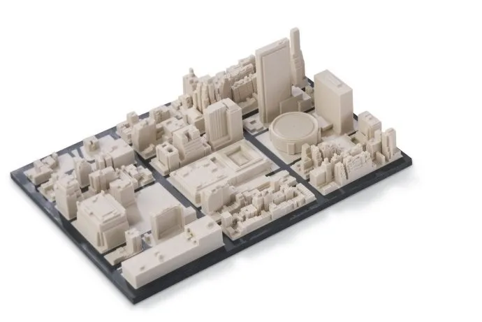
Laney LA’s architects use 3D printing to create models that allow them to view the project from a fresh perspective while simultaneously providing vantage points.
“It's fun to always try to depict a certain idea about the project and isolate that through the model, whether it's a certain room or a space that we want to highlight through a section cut of the model, or even the topography of the site,” Choi said.
RPBW’s model makers use a Form 3 SLA printer to speed up the production of scale models.
When it comes to 3D printing architectural models, not all methods are created equal. It is important to choose the right printing technology for specific use cases.
The most popular 3D printing technologies for architectural models include stereolithography (SLA), fused deposition modeling (FDM), selective laser sintering (SLS), and binder jetting.
Stereolithography was the world’s first 3D printing technology, invented in the 1980s, and is still one of the most popular technologies for professionals. SLA resin 3D printers use a laser to cure liquid resin into hardened plastic in a process called photopolymerization.
SLA parts have the highest resolution and accuracy of all plastic 3D printing technologies. SLA parts also offer the smoothest surface finish that is easy to paint.
SLA parts have sharp edges, a smooth surface finish, and minimal visible layer lines that are ideal for highly detailed presentation models. This model was printed on a Form 3 SLA printer.
SLA is a great option for highly detailed presentation models for presenting concepts and ideas to clients or the public.
Thanks to fast-printing materials like Draft Resin, SLA is also the fastest 3D printing process for most parts. While desktop SLA printers offer a more compact build capacity, with large-format SLA 3D printers like the Form 3L, architects and model makers can create truly large-scale models.
Sample part
See and feel Formlabs quality firsthand.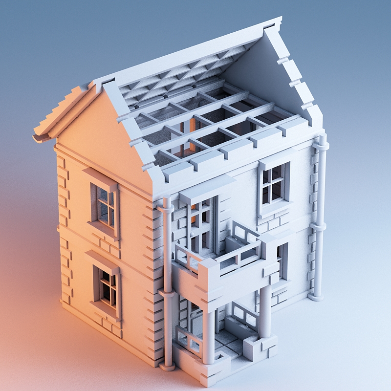 We’ll ship a free sample part to your office.
Request a Free Sample Part
Fused deposition modeling (FDM), also known as fused filament fabrication (FFF), is the most widely used form of 3D printing at the consumer level, fueled by the emergence of hobbyist 3D printers. FDM 3D printers build parts by melting and extruding thermoplastic filament, which a printer nozzle deposits layer by layer in the build area.
FDM has the lowest resolution and accuracy from the four 3D printing processes and is not the best option for printing complex designs or parts with intricate features. It is ideal for basic concept design models produced during the initial stages of design as it can create relatively large models fast and at a low cost.
FDM printers struggle with complex designs or parts with intricate features (left), compared to SLA printers (right).
Selective laser sintering is the most common additive manufacturing technology for industrial applications.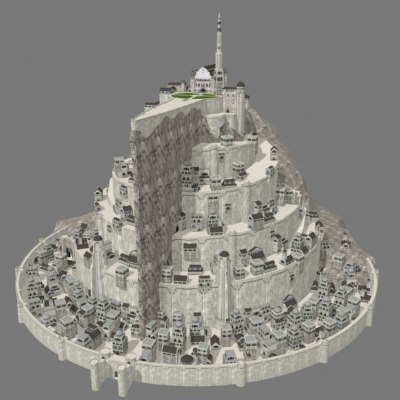 SLS 3D printers use a high-powered laser to fuse small particles of polymer powder. The unfused powder supports the part during printing and eliminates the need for dedicated support structures.
SLS printing is ideal for complex geometries, including interior features, undercuts, thin walls, and negative features. Parts produced with SLS printers have excellent mechanical characteristics that make them suitable also for structural parts.
SLS is ideal for complex geometries and intricate details. The details on this model were printed on a Fuse 1 SLS printer.
Binder jetting 3D printing technology is similar to SLS printing but uses a colored binding agent to bond powdered sandstone material instead of heat. Binder jetting printers can produce vivid, full-color 3D architecture models.
Parts produced with binder jetting have a porous surface and are very brittle, which means that this process is recommended only for static applications.
Binder jetting printers can produce vivid, full-color architecture models.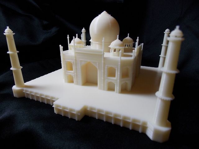
| Stereolithography (SLA) | Fused Deposition Modeling (FDM) | Selective Laser Sintering (SLS) | Binder Jetting | |
|---|---|---|---|---|
| Resolution | ★★★★★ | ★★☆☆☆ | ★★★★☆ | ★★★☆☆ |
| Accuracy | ★★★★★ | ★★★★☆ | ★★★★★ | ★★★☆☆ |
| Surface finish | ★★★★★ | ★★☆☆☆ | ★★★★☆ | ★★★☆☆ |
| Ease of use | ★★★★★ | ★★★★★ | ★★★★☆ | ★★★★☆ |
| Complex designs | ★★★★☆ | ★★★☆☆ | ★★★★★ | ★★★☆☆ |
| Build volume | Up to 300 x 335 x 200 mm (desktop and benchtop 3D printers) | Up to 300 x 300 x 600 mm (desktop and benchtop 3D printers) | Up to 165 x 165 x 300 mm (benchtop industrial 3D printers) | Up to 254 x 381 x 203 mm (industrial 3D printers) |
| Price range | Professional desktop printers start at $3,500, large-format benchtop printers are available from $11,000. | Budget printers and 3D printer kits start at a few hundred dollars. Higher quality mid-range desktop printers start around $2,000, and industrial systems are available from $15,000. | Benchtop industrial systems start at $18,500, and traditional industrial printers are available from $100,000. | Binder jetting 3D printers are expensive industrial machines, with prices ranging from $30,000 to $100,000+. |
A team from the Institute of Architecture at the Hochschule Mainz - University of Applied Sciences reconstructed the medieval german cities of Worms, Speyer, and Mainz with large-scale 3D printed models.
Most architects today already work in the digital space, using architectural CAD software like BIM (Revit and ArchiCAD), Rhino 3D, or SketchUp to create digital CAD designs. However, these digital files cannot always be used to create the physical scale models directly with 3D printing.
A successful transition from a CAD model to a 3D printable file relies on a baseline understanding of design for 3D printing, how regular modelmaking constraints relate to preparing a file for 3D printing, and how to approach and make smart modeling decisions, from choosing the right scale to designing for assembly to post-processing.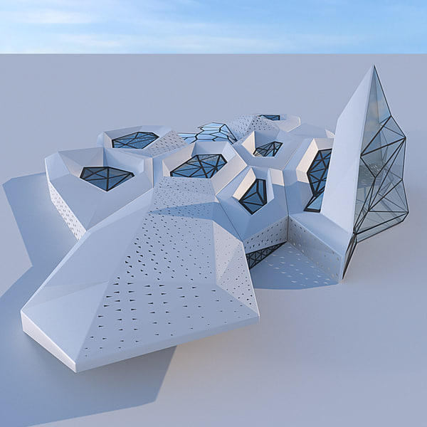
Architectural models are conventionally assembled with a variety of materials and components. 3D printers help fuse these components into as few individual parts as possible, but some assembly is still required for two reasons:
-
The constraints of the build volume: Unless you’re using a large-format 3D printer such as the Form 3L, you might need to divide the model into multiple parts to fit it inside the build volume of the 3D printer.
-
The need to show interior detail or materiality: Certain models require components that come apart to reveal more information about the design.
The size and geometry of different components within an architectural model are key considerations when preparing an architectural model for 3D printing. Generally, large models, models with multiple components, and models with intricate features are split into 3D printable components for assembly. Parts can then be easily joined together through chemical adhesion or mechanical assembly; the high accuracy of the prints with technologies like SLA and SLS ensures that the parts join together seamlessly.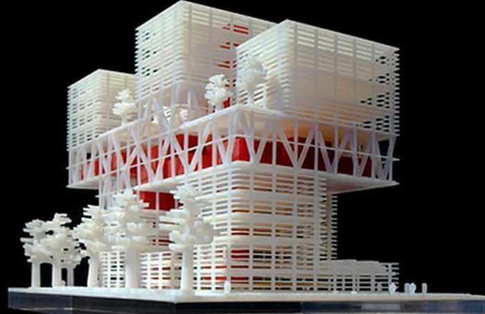
Getting the best results requires applying modeling strategies for assembly, including:
Since each housing unit followed the same design, it made sense to simply print one removable unit that would allow the client to understand the generic unit typology. Model by Stanley Saitowitz | Natoma Architects Inc.
Advancements in CAD technology have drastically simplified the process of developing 3D printable files. Modern CAD platforms have dedicated 3D printing modules to help architects convert a CAD design into a printable model. However, do remember that you are still working at a 1:1 scale–some quick conversions will be required to achieve the correct dimensions at the print scale.
Developing architectural models require some important considerations depending on the CAD platform used. These CAD-specific considerations include:
-
BIM Workflow: Developing 3D printable models with BIM software that leverages parametric modeling such as Autodesk Revit or Graphisoft ArchiCAD requires some component management.
 Components such as ductworks, double glazed windows, and HVAC systems do not translate in 3D prints and must be removed, while other parts such as doors, windows, walls, slabs need to be thickened.
 -
Surface Modeling Workflow: This workflow is often an easier approach, starting from 2D drawings solely with the intention to 3D print. It involves exporting a simplified drawing, scaling it down, and extruding and trimming until there’s an external shell.
Download our white paper for step-by-step workflows in common architectural CAD software ecosystems.
The next step in 3D printing architectural models is transcribing your digital 3D model into a language your 3D printer understands. Accomplishing this requires the use of slicing or print preparation software, such as PreForm. Whether you’re new or experienced, slicing software is generally intuitive to use. The software highlights details such as walls that may require strengthening, unsupported areas, and closed volumes that affect the structure of the 3D print, which can be addressed before printing. Using the software, you can also optimize settings such as resolution, build platform position, and support structures.
Materials play an important role in conveying the underlying concept of a design. It isn’t always imperative to simulate the exact color and texture of a material, but it can help to distinguish between different materials. Splitting a model by its components makes it possible to display materiality, as parts can be produced with various 3D printing materials, or individually painted with different colors.
This site model was created with laser-cut chipboard. The primary building was 3D printed with both Clear Resin and White Resin. Model by Schwarz Silver Architects.
Post-processing differs depending on your specific 3D printing technology, but generally includes sanding, bonding, and painting models.
Here’s an overview by 3D printing process:
| Post Processing Technique | Stereolithography (SLA) | Fused Deposition Modeling (FDM) | Selective Laser Sintering (SLS) | Binder Jetting |
|---|---|---|---|---|
| Sanding | Light sanding is recommended to remove support marks.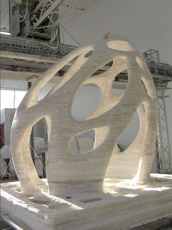 | The lower quality of FDM prints means sanding is required to get a smooth finish. | No sanding is required due to the quality of the finished parts. | No sanding is required. |
| Bonding | Bonding of SLA components is done with super glue or liquid resins. | FDM components can be assembled using adhesives such as super glue. | SLA components can be assembled using adhesives such as super glue. | Components printed using binder jetting printers can be bonded using super glue. |
| Priming and painting | SLA components can be painted to achieve the desired finish. | FDM components can be painted to achieve the desired finish. | SLS components can be painted to achieve the desired finish. | No painting is required for full-color parts. |
Professional SLA and SLS 3D printers empower architects with the tools to create accurate and attractive 3D architectural models.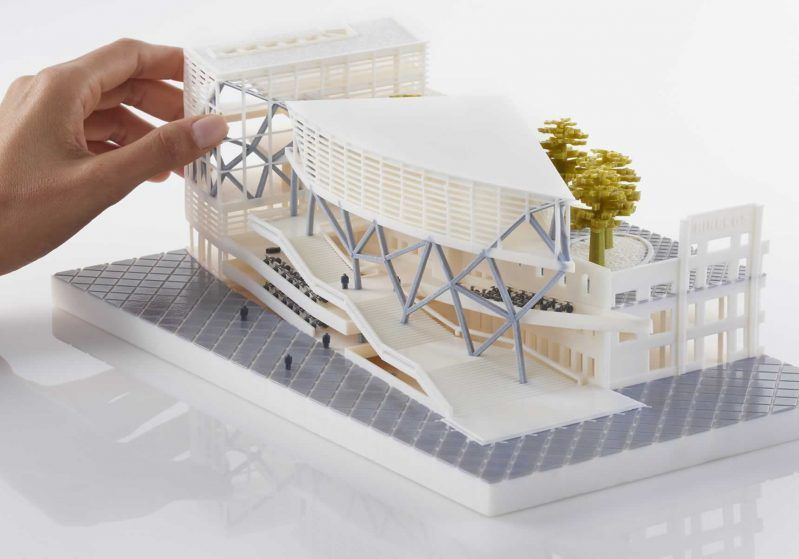 Choose the Form 3 for a compact solution that can fit on a desktop, the Form 3L for high resolution large-format models, and the Fuse 1 for structural parts and the most complex shapes.
See the Form 3See the Form 3LSee the Fuse 1
Download our white paper for an in-depth overview of modeling strategies, step-by-step workflows in common architectural CAD software ecosystems, as well as printing and post-processing recommendations.
Download the White Paper Now
Download paid and free designs for 3D printing about Architecture・Cults
« Can you feel the Tower of Cults? » G.Eiffel
Build-yourself architectural masterpieces proposed by the best designers of 3D printing. Whether modern, contemporary or classic, Cults conceals ultra-chic urban treasures! Download free 3D models and make them with your 3D printer. Have fun!
Qatar Lusail Stadium
€60
Mountain school building - chilean army
€70
Pump lamp
€1
flowers and leaves relief-mold
€1
TUNNEL DIORAMA 01
€11.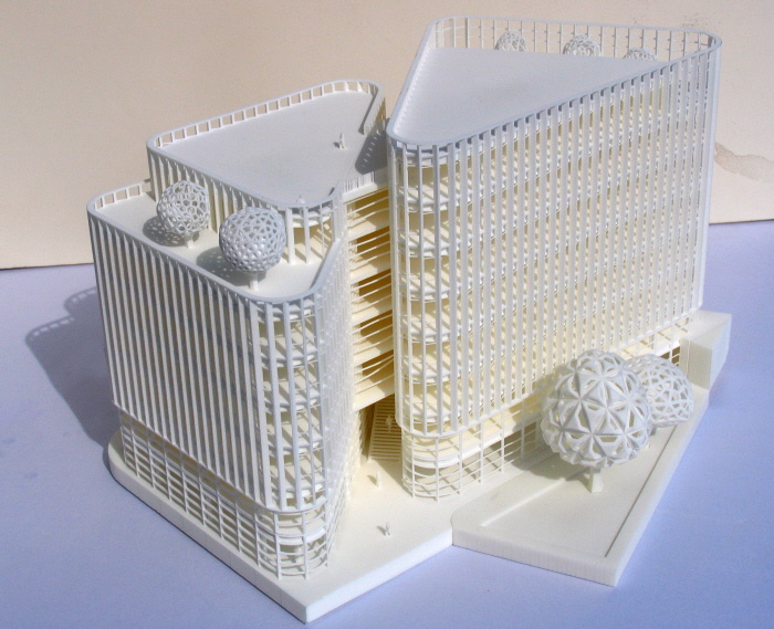 94
94
Modern ruins pack No. 1 - Flames of war Bolt Action WW2 Modern
€41.90
Model House - P1 and P2
Free
Ductati pineagle-type sports spoiler
€1.98
ps5 + controls
€0.64
horse
€0.64
Tomb of Lihyan Son of Kuza
€9
PROFILES FOR WOOD DOWELS
Free
sign foR order
€3
Scale Shop Windows
Free
Dantes Underworld Ancient Stone Walkways Pillars Kit bash
€25.38
Dantes Underworld Ancient Stone Walkways
€17.30
See all 3D models
Himeji Castle
€5
Trullo from Alberobello, Puglia, Italy
Free
Birdhouse
€5.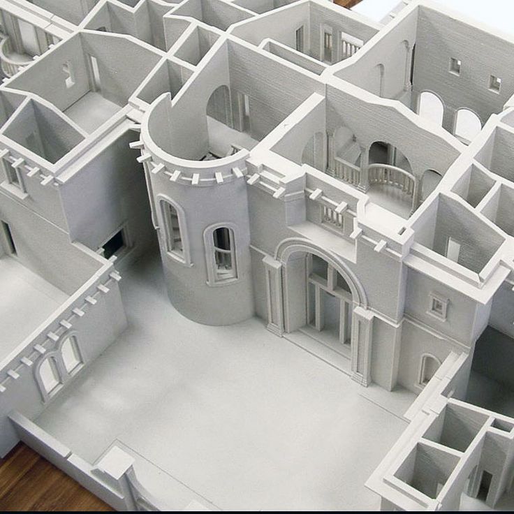 94
94
Church of Metekhi -Georgia-
Free
Simple Eiffel Tower - 10mins Modeling
Free
FLEXI new year tiger cat
€3.12
Civilian War Memorial (Singapore)
€2
Oogaki Castle
Free
Dallas Cowboys - ATT Stadium
€14.88
Car Port Garage Scale 143 Dr!ft Racer Storm Child Diorama
€2.99
PETALS LIGHT
Free
My angkor wat(1:2400)
Free
Parametric Office Table
€3.20
Boeing 777-200 1:750
Free
Empire State Building 87cm height (87cm height) + LED
Free
Prague the Pirate City
Free
Best selling 3D files of the Architecture category
Toretto house v2
€4.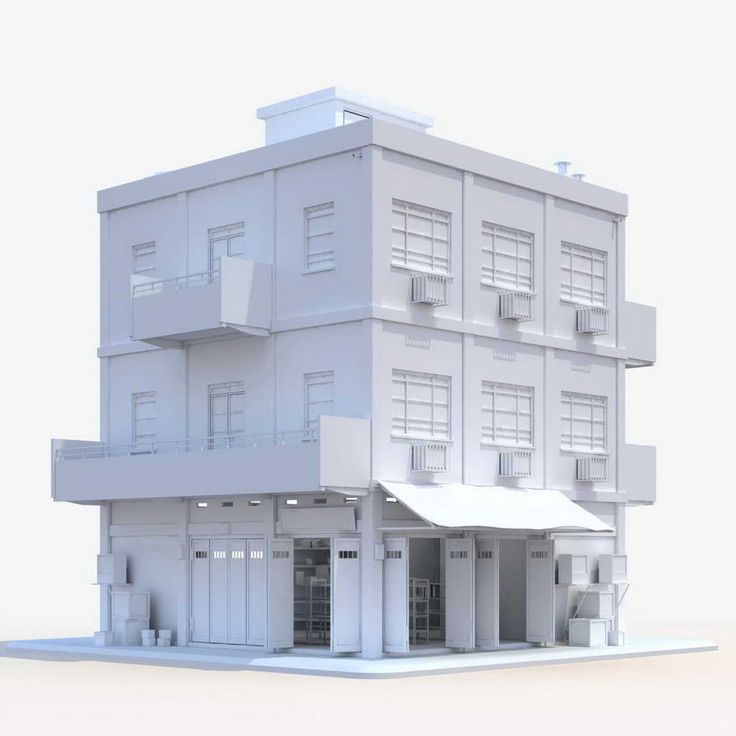 98
98
Kandarian Dagger ,evil dead
€2.60
Airbus A330-200 1:500
€0.50
Leaning Tower of Pisa
€2.50
Roman Coliseum
€0.70
Oil drum furniture set - chair, table and sofa
€3.79
Eiffel Tower - Paris City
€0.99
London City - Skyscrapers
€0.99
The Myers House
€11.54
CLUMSY PRINT-IN-PLACE SPIDER Flexi
€3.12
LONDON CITY - Miniature 3D Map
€4.86
Ancient Raven Castle
€4.98
Pumpkin Cottage
€4.80
New York City - Manhattan - Model for 3D Print
€1.40
1-100th scale furniture Architecture
€0. 75
75
WIndows set - 34 PCS
€3.26
Most downloaded free STL files in the Architecture category
Eiffel Tower Model
Free
Eiffel tower
Free
eiffel tour
Free
615 mm Eiffel Tower
Free
Chateau Disneyland Paris with Prusa MK2S MMU (Ed2)
Free
Medieval Castle
Free
Hogwarts School of Witchcraft
Free
Famous Paris buildings
Free
VASE-06
Free
Eiffel Tower HD
Free
pantheon
Free
Place de la republique, Paris
Free
Disney Castle
Free
statue of liberty
Free
Spiral Tower
Free
Eiffel tower
Free
Architectural 3D Printing Modeling Strategy and Software Usage Guide
At a Glance
3D printing provides tremendous benefits to the conventional architectural workflow.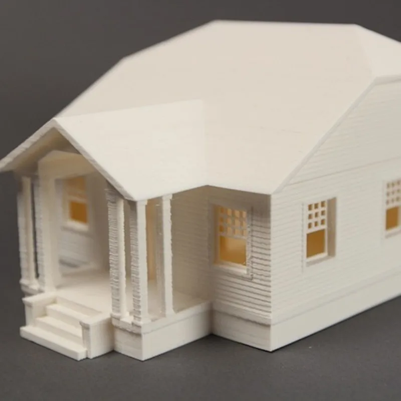 You can print complex designs without the need for skilled craftsmen, and quickly modify these designs without too much difficulty. Stereolithographic (SLA) 3D printing delivers incredibly high surface quality and detail, making it suitable for architectural applications. This paper explores modeling strategies and software workflows that enable architects and designers to easily integrate 3D printing into existing design methodology, create best practices based on internal testing by Formlabs and architecture firms, successfully using Form 2 to create 9 models0005
WHAT YOU WILL LEARN:
Strategies for designing 3D printed architectural models
Tips for improving your workflow Pre-print processing software
- Building information model (Revit, ArchiCAD)
- Surface modeling (Rhino, SketchUp)
Good post-processing techniques
- Compound
- Finishing
Introduction
The 3D printing market today offers affordable options in both price and scale.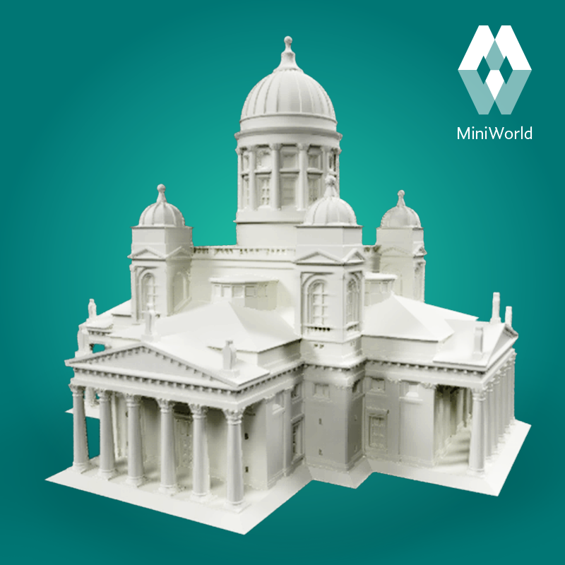 While professional-grade technology used to be costly, desktop stereolithography 3D printers allow architects, designers, and model makers to offer high-quality, in-house fabricated parts.
Most models cost less than $10 per part.
3D printing opens up opportunities to create complex designs with less effort and fewer materials, but the successful transition from a CAD model to a printable file is based on a basic understanding of design for 3D printing. This document will help you understand how standard modeling constraints relate to preparing a file for 3D printing, as well as approaches and decision making for intelligent modeling - from scale selection to design and assembly for post-processing.
To integrate these strategies into existing workflows, this booklet explores ways to approach modeling strategies tactically by examining three of the most common software ecosystems: allows you to include small details even on the smallest models. This example of a small city model has a scale of 1/32″ = 1’ and is completely printed on a Form 2 3D printer.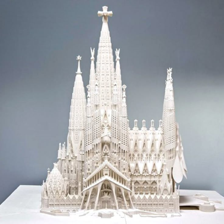 Many small details and parts of this design will take significantly longer if cut and assembled by hand. Model from LaneyLA Inc.
This auditorium section was 3D printed as one piece on a black resin Form 2. Model from DLR Group.
Modeling strategy
Architectural models are usually assembled using various materials and components. 3D printers help combine these components into as few separate parts as possible, but assembly manipulation is still necessary for two reasons:
- Build Volume Limitations : High build volume printers are either expensive or compromise on surface quality. Form 2 build volume is 57 x 57 x 69 inches (145 x 145 x 175 mm)
- Need to show interior details or materiality : Some models require components to be separated to show more design information.
DESIGN FOR ASSEMBLY
All 3D models require preparation before they can be sent to the 3D printer. In the case of architectural models for the Form 2, this often involves splitting the model into smaller parts to fit the scope of the Form 2 build. The parts can then be easily joined together by chemical adhesive or mechanical assembly; high precision printing ensures that the parts fit together.
Dimensioning for parts to be separated must take into account the final orientation of the model. Most architectural prints need to be oriented at a 45 degree angle due to floor slabs being considered large horizontal projections. Dividing the model into long, thin parts helps maximize the diagonal length of the build volume while achieving perfect orientation
Strategy overview
There are several strategies for assembling 3D printed models. Your strategy will depend on what you hope to represent with the design, as well as the scale and geometry of the model. Consider the following parameters:
- Need to show internal or external parts
- Easy Split (You want to split the model by the least complex part of the model)
It is necessary to show a certain part of the program: typology, structure, floor layout
| Seam separation | Separation by component |
| Section model | Separation by program |
| Straight cut | Separation by structure |
| Aligners |
Splitting at the seam
STRAIGHT CUT
The easiest way to split the model is with a straight cut.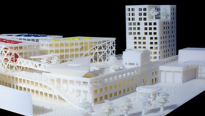 This is a simple command to execute in most CAD software. The bridge model is divided lengthwise using straight cuts into four parts, one of which is shown above. Each support post is inserted into
mating hole that does not require glue. Regardless of which method you choose, if you have a large number of parts (more than 10), it can be helpful to add a unique identifier for each part to help solve the puzzle during assembly.
Pros:
- Least heavy use of CAD
- Greater tolerance for prints that warp or have a higher degree of dimensional change
Cons:
- Assembly requires manually leveling each piece and fixing it in place until the adhesive is fully bonded
Try to print all components in the same orientation so that the layer lines and subsequent dimensional inaccuracies follow the same pattern.
ALIGNMENT TOOLS
Another approach is to add features to the design that will allow the prints to align.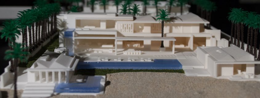 When adding mate fixtures, try to subdivide the model in areas with the least complex geometry. Use the CAD tool of your choice to split your model and add basic alignment fixtures such as slots, pins, grooves, recesses and flanges, or more complex fixtures such as dovetails and cuts that follow existing model curves. In addition, it is important to create a design with ~0.25 mm tolerance between mating parts to prevent additional sanding at the post-printing stage.
Pros:
- Easy alignment Parts that are not accurate
- Easy to assemble (mating parts help create a large surface area for adhesion)
- High precision SLA allows tight fit with high tolerance and can be used without adhesive
Cons:
- Parts that are not true to size will not fit well. High fine details are often less accurate.
SECTION MODEL
The separation of the model with a seam has the additional task of showing the section model for structures with irresistible interior details. Initially, the model can be presented as a whole to the client, and then disassembled to reveal interior details as desired. These LaneyLA examples show how the same model conveys different types of information based on open and closed configurations
This model from LaneyLA was printed on a White Resin Form 2.
Using devices for combining: Methods component
SOFTWARE DIVISION
By splitting a building with software, you can represent the building as a set of parts, providing a clear understanding of all design components without a plan and section drawings. You can print each floor slab separately and then assemble using mates, or just print one component of the entire building separately from the rest. A good example is the model from Stanley Sitetowitz | Natoma Architects Inc (SSNAI), who used the Form 2 to model the residential complex.
Model by Stanley Sitetowitz | Natoma Architects Inc.
Since each body block followed the same pattern, it makes sense to simply print one detachable block that will allow the customer to understand the typology of the typical device. to print as a single block or separate along the seam.
This method usually works for models that do not have straight lines, such as typical building blocks, but complex structures, such as detailed building sections, bridges, pavilions, or airports.
First, break these models down into components that can be 3D printed with minimal supports. This saves post-processing time (removing supports for delicate models can be tedious) and reduces material costs and print times.
This bridge example demonstrates multiple partitioning methods. First, the model is divided into several parts (Figure a). Although they fit the
Form 2 build platform, they require painstaking removal of supports around more delicate areas such as cables and railings.
To solve this problem, each part is broken down into three sub-components: base plate and railing, vertical tensile cables and solar panels on top (figure b). They can be printed with significantly fewer supports, making it easier to finish,
Once completed, the components simply need to be assembled using the alignment functions that were included in the design phase. Smaller parts are also easier to place on a single build platform, with the entire bridge being printed from five 100ml parts.
Model from T.Y. Lin Architects
This site model was created using laser-cut fiberboard. The primary building was 3D printed from clear and white resin. Model by Schwarz Silver Architects
Materials
Materials play an important role in conveying the basic design concept. It is not always necessary to model the exact color and texture of a material, but it can help separate different materials. Dividing a model into its components allows for the display of materiality, as parts can be printed in different materials or individually dyed in different colors.
The transparent façade is illuminated from within, simulating the visual conditions of this site at night.
Formlabs Matte Resins
Black, White and Gray out of the printer have a smooth, opaque finish and provide an excellent neutral palette for architectural models. Gray and white resins are also easy to process and can be finished with just a few coats of paint, as discussed further in the finishing section of this document.
Formlabs Clear Resin is excellent for printing features that mimic translucent materials. If your model requires more transparency, you can simply dip the printed part in clear resin and let it dry evenly, as described in this article on making clear resin parts. You can also spray any clear coats on the model to increase the transparency and glossiness of the surface.
3D PRINTING AND TRADITIONAL MATERIALS
This model uses the Form 2 to print very fine details such as the cornice, clock and railing. Model by Miles Burke Architectural Models Inc.
Instead of 3D printing an entire building, sometimes it's better to print just the complex components. Complex facades, slings and cornice details are excellent candidates for SLA 3D printing. Flat walls, floor slabs and topography can be laser cut or even hand-drawn
This complex façade is parametrically designed from solar trajectory analysis and would be incredibly difficult to fabricate in any other way at this scale.
Software workflow
Good printing comes from a well-designed 3D model. This section will cover modeling best practices and workflows for printing in some of the most common CAD environments:
Revit, SketchUp and Rhino
CAD software is typically the bottleneck in the transition from drawing to 3D printed model
General workflows
IMZ workflow
IMZ workflow
Model → Revit3Diagnostics → Sketch3Diagnostics 900 PreForm
Although BIM (Building Information Model) software is popular with architecture firms, it is not always used for direct 3D printing models. There are some high level steps that you can take
take to create a 3D printed model from these programs. This workflow is widely applied to Autodesk Revit or Graphisoft ArchiCAD software, both of which are IMZ parametric modeling programs.
PREPARE THE FILE
STEP 1: Prepare a stand-alone file
STEP 2: Component Management: remove ducts, double glazing, HVAC units and internal parts that will not be visible in model
STEP 3: Select all components to be sealed (eg doors, windows, walls, slabs). The parametric nature of the model allows you to simultaneously compact the dimensions of several objects.
EXPORT FILE
Select the scale at which you want to export the file. Select export options depending on the needs of your model:
EXPORT AS STL
Exporting the file as a mesh is very difficult to manipulate, so this is only useful if you don't want to edit any geometry after this step. You can then use your software to correct the mesh of your choice, as well as subdivide the mesh along the main Cartesian planes.
EXPORT AS 3D DWG
Export as surfaces allows you to easily manage and edit geometry in Rhino or SketchUp. This step is recommended for those who want to split the model programmatically or by component, or split by a seam that is not on the normal Cartesian plane. You can then export the STL file from Rhino or from SketchUp using the plug-in
EXPORT USING ARCHICAD
Perform a geometry transformation to Morphs and a "consistency check" before exporting the model as STL. When printing in parts, use tool
"Divide" to cut the model for multiple print platforms, if needed. This operation basically creates printable files, but a quick check in mesh repair/analysis software never hurts.
USING STL REVIT EXPORTER
This method automatically removes smaller details such as doorknobs and railings.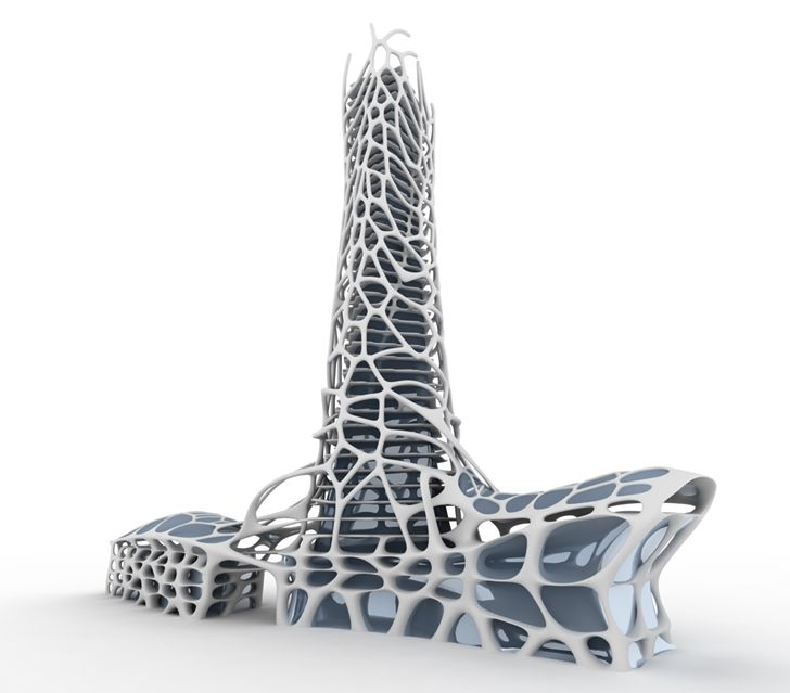 However, it is not reliable and still often requires some post-processing in other CAD environments before being sent to print.
Surface Modeling Workflow
AutoCAD → Rhino/SketchUp → Model Diagnostics → PreForm
This workflow is often an easier approach and starts with 2D drawings solely for the purpose of 3D printing
FILE PREPARATION
STEP 1: Hide unwanted layersSTEP 2: Identify and remove unnecessary elements such as furniture, trees, etc.
EXPORT FILE
STEP 1: Export the simplified drawing from Rhino as DWG
STEP 2: Import into Rhino
STEP 4: Start extruding and trimming until you get the outer shell.
STEP 5: Export as STL STEP 6: Mesh Analysis/Correction STEP 7: Import to PreForm
Note: If the model will be printed in several parts, split it before exporting as STL
THICKNESS WITH RHINO
Instead of parametrically controlling the thickness of components directly in the BIM file, you can also use the BoxEdit component in Rhino.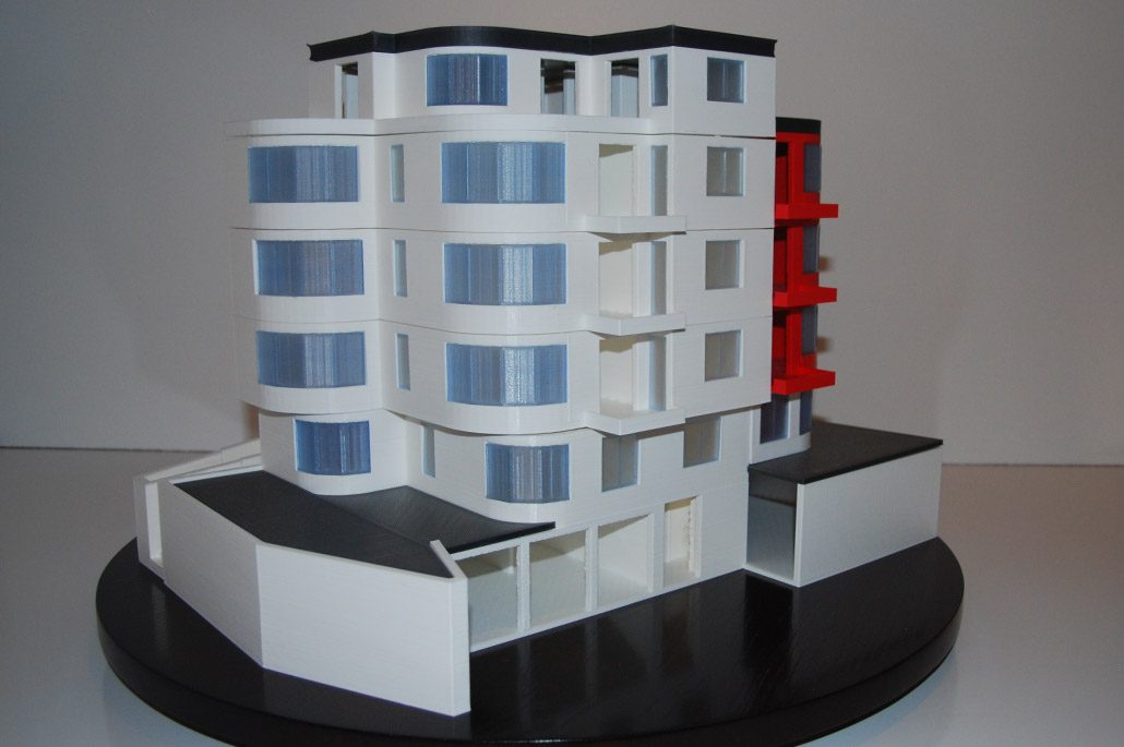
This allows you to simultaneously scale a number of elements with respect to their center lines. BoxEdit is ideal for models that need to be scaled parallel to three Cartesian axes. Non-uniform scaling is a little trickier.
For non-rectilinear geometries, we suggest converting the part to a mesh and then using the Weaverbird thicken command, which simply offsets any non-standard mesh geometry outward by a given distance. Alternatively, it is possible to "split" complex parts into surfaces and then offset them instead of importing volumes from Revit.
SELECTING SMALL GEOMETRIES WITH RHINO
Another valuable Rhino feature is the SelSmall command, which allows you to select all elements in the Stage that are smaller than a custom bounding box. You can then select those objects and use
BoxEdit for individual scaling or just remove them. This is useful when you are dealing with a file that does not have a well organized layer system.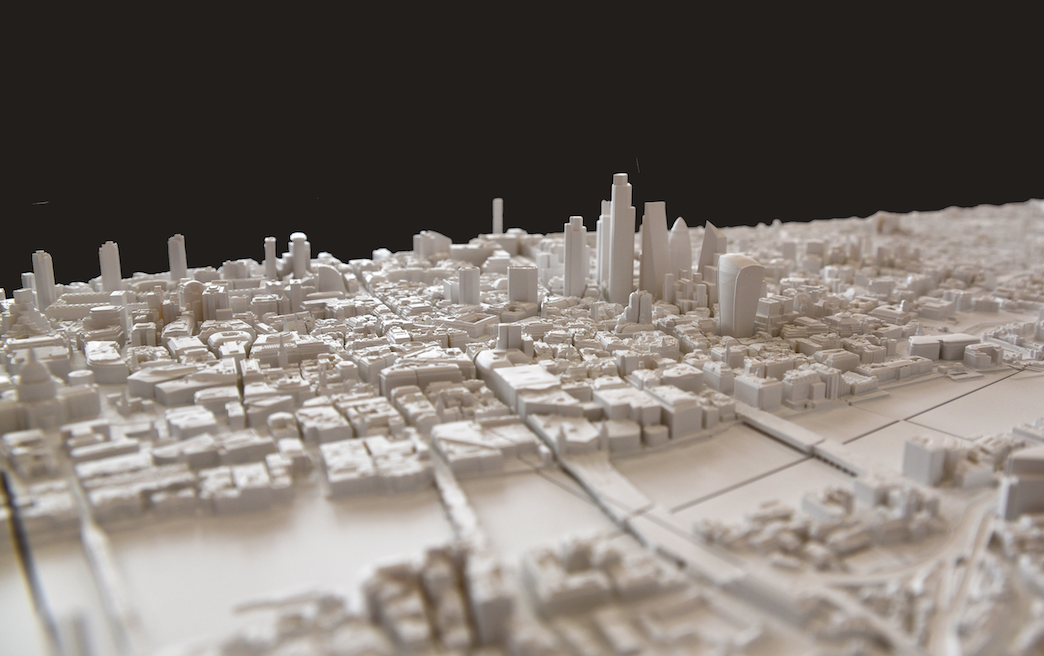
Although performing a logical connection on all geometries is ideal, often the problem can be solved with simple overlapping geometries. PreForm will interpret them as one closed geometry in most cases, but be sure to check printability with the "slicer" tool in the right pane in PreForm
. CONTINUOUS / LOGICAL JOINT GEOMETRY
Note : PreForm is Formlabs free software that prepares your 3D model for printing in Form 2. Once the part is set up, you can save it as a FORM file for future use in preform.
COMPUTATION WORKFLOW
Although it is a less common workflow, computational design is slowly being introduced into mainstream architectural workflows. Software such as Grasshopper and Dynamo are used to create parametrically generated geometries that are often so complex that they can only be created with 3D printing.
Since geometries are already easy to manipulate, it's usually best to create a separate component that allows you to easily control the basic dimensions of all thin objects.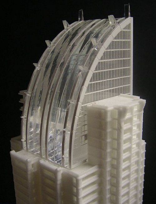 In this case, it's a simple matter of trial and error; running the exported geometries with a print test (PreForm,
MeshMixer) and resizing until you arrive at a printable file.
Model Diagnosis
All workflows described below share a potential "generic diagnosis". This is an optional (but often necessary) step to ensure that the model is fully printable. Free programs such as Autodesk's MeshMixer and Netfabb are tools that allow you to repair, smooth, cavity, and split 3D print files.
MESH FIX
Formlabs PreForm software uses Netfabb's built-in mesh fix, so NetFabb and MeshMixer must be used for custom fixes or to preview problem spots in print. Materialize Magics is a great proprietary tool that covers the entire preprint workflow for a wide variety of printer types. The mesh patching software part is most important to the Form 2 print workflow and can save you a decent amount of preparation time. Netfabb has a beautiful built-in model cutter that allows you to effectively split and restore large files along any Cartesian plane.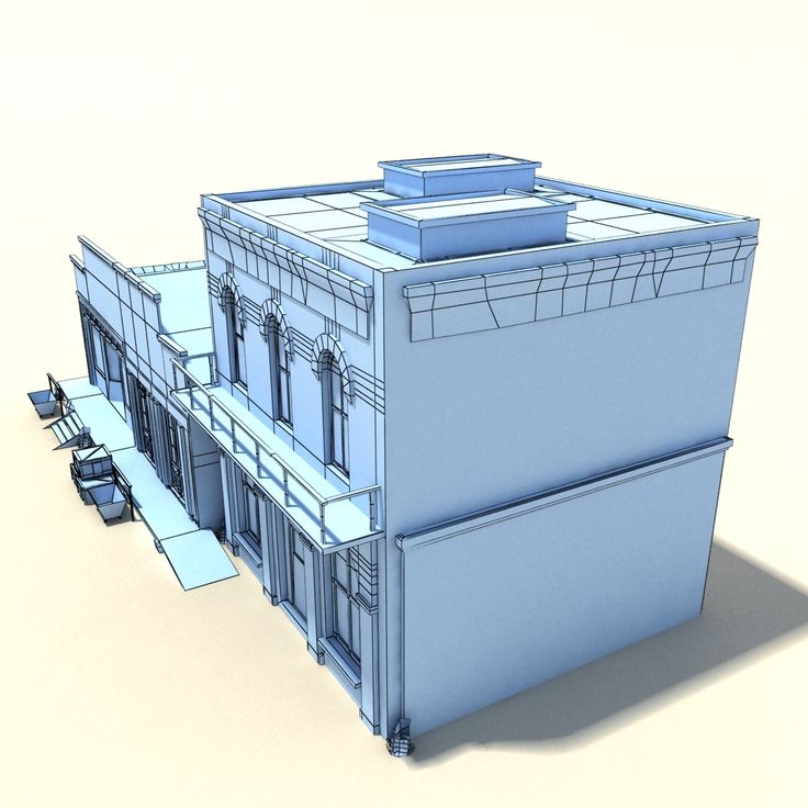
SPLITTING THE MODEL
You can also split the model in NetFabb, which splits and fixes the split parts into printable volumes. In Rhino, you will need to close open volumes. Be sure to leave a tolerance of ~0.25mm between adjacent parts, this will allow them to be inserted without friction.
For more information on tolerances, see our white paper.
PREFORM SLICER
Architectural models are very detailed and it is often difficult to isolate each print issue. A combination of the above practices and mesh repair software is usually used for almost all problems, but it's always wise to use the PreForm Slicer tool to make sure there are no thin unsupported areas and enclosed volumes (such as rooms with no doors, elevator shafts, and parking spaces) .
“Building and architecture structures are not meant to be 3D printed, they are meant to be built. This creates problems of scale and complex geometry. By combining Netfabb's powerful mesh repair tools with the precision of the Form 2, you can prototype and visualize designs faster and in more detail, benefiting more for your business and speeding up your project's design review process.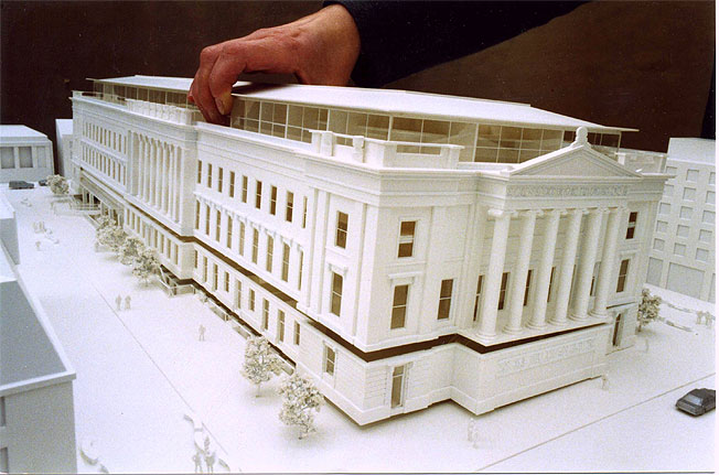 ”
”
Matt Lemay. Lead Enterprise Solutions Provider, Autodesk Customer Service
Post-Processing
Joining
The modeling strategy section of this booklet covers some ways of splitting and aligning parts together, but glue is always needed to securely join. Architectural parts are bonded in two main ways:
CYANOACRYLATE
Cyanoacrylate (CA or Super Glue) creates a fast, strong enough bond, ideal for small to medium sized parts. CA does not bond dirty surfaces well, so be sure to thoroughly clean the part before applying adhesive to the surface of the model.
POLYMER
For smaller prints, you can use liquid resin as a binder. Dispense a small amount of resin into the tray from a bottle or cartridge, use a dropper or syringe to lift it up, and place it on the surface of the part to be bonded.
Join parts and wipe off any excess resin that may be spilling around the edges. To cure the resin and bond the parts, use a 5 mW laser pen at 405 nm and point it at the bonding area around the parts.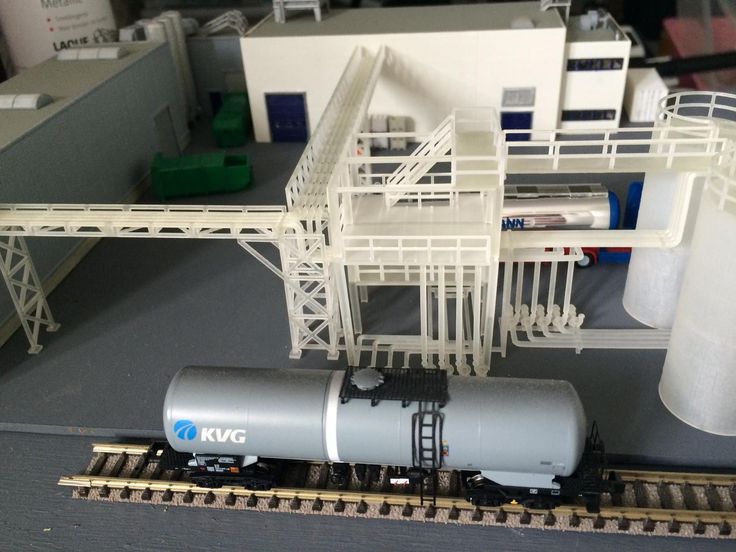
This method creates a chemical bond, just as if the part had been printed on your SLA 3D printer, but only applies to small bonding surfaces because a low power laser pen cannot penetrate the model deep enough to create a strong bond .
FINISHING
Parts printed on Form 2, especially matte standard resins, have a smooth surface as soon as they exit the printer. However, visible areas with supports almost always require sanding. In addition, you can prime and paint parts in any desired color.
GRINDING
Sanding will help you remove the support marks and any remaining inaccuracies from your model. Start by carefully dry sanding the surface of the part using ~150 grit sandpaper to remove large support marks and smooth out the edges of the joint. Once the surface of the part is smooth, wet sand with 320mm sandpaper to remove any remaining layer lines. Move the sandpaper randomly to avoid grain formation.
In most cases these two steps will create a fairly even finish, but you can continue to increase the grit size of the sanding paper by a factor of 2 and wet sand the entire piece until the surface is smooth enough.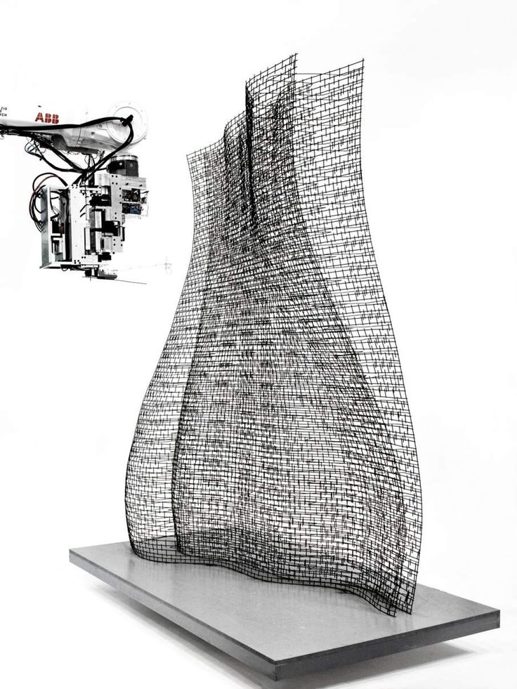
Once you have finished sanding your model, wash the model in soapy water to remove any dust or debris and dry thoroughly before proceeding to the last step.
The architectural models are very detailed and it is quite difficult to access certain areas with only sandpaper. You can use different sizes of nail files to get to problem areas of the model.
PRIMER AND PAINTING
Priming is required before parts are painted to ensure the paint adheres to the surface. Priming can also make it easier to find areas that require additional finishing. A quick spray of primer over the model makes the support marks very visible, so you can instantly identify areas that need additional sanding.
General plastic primer gray matt shows details very well. Apply it to surfaces in several thin layers for best results. Continue sanding in critical areas, reapply a light coat of primer and repeat this process until the entire part is smooth. Most spray paints work best in warm, slightly damp conditions with no airflow, but always check the specific paint or data sheet for manufacturer's recommendations.
“Models are becoming rarer in a field where photorealistic renderings and virtual reality technology are advancing, but physical models allow architects to test spatial qualities in ways that digital models cannot. If we weren't using a 3D printer, we would be forced to spend more time visualizing designs through renderings and drawings. Being able to get a physical model of a complex design straight from a 3D CAD model gives us several impressive looks in less time.”
Paul Choi
3D -ip in the architecture
Visual embodiment of
Protecting ideas, winning the business
How it works
Savings
Digital model of the building made the design more efficient, and 3D-flip mockups has given businesses opportunities that were previously only dreamed of.
3D digital modeling (BIM) is used today by half of the architectural companies in the world, and few argue with the fact that the advent of BIM has made a real revolution.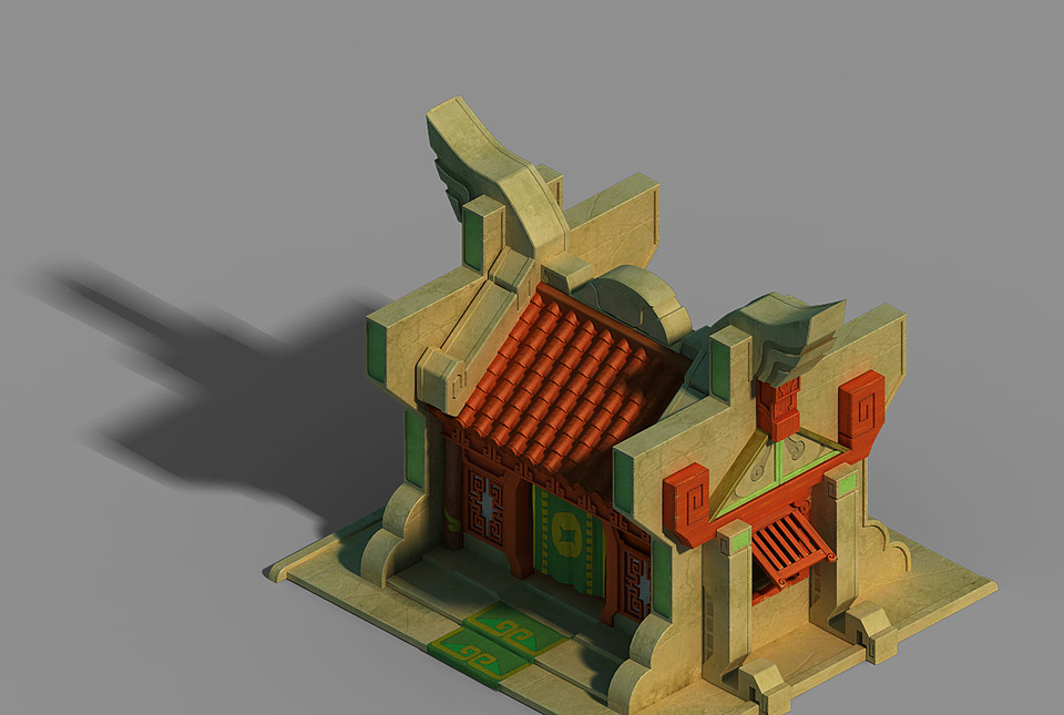 Architects have finally got the perfect way to quickly, clearly, visually and accurately convey their ideas to the customer.
It's time to master the innovative technology of the presentation of the physical model. The physical model is much more complete than the picture on the monitor, allowing the customer to understand and feel the architectural design. The architect also needs both models: a digital 3D model is required to analyze the components of the project, and a physical model is required to effectively assess the details and scale. More importantly, the physical model allows architects to speak in a language understandable to the customer, even the most distant from architecture. The client, on the other hand, gets the opportunity to evaluate the project on an emotional level, to perceive it taking into account all the subtleties.
Building a house: 3D printing as the engine of project Throughout his 20 years of work in the field of computer-aided design, R. The usual answer is something like: "Accelerate time to market for our product." With regard to architecture, Parthasarathy found that the two main causes of delays came down to lack of theoretical study of the project and poor communication. Two years ago, he discovered 3D printing, a completely new technology that significantly reduces design time. It allows you to make an accurate three-dimensional physical model of the building and make it an important element in the work of every designer. Partha saw this as a great opportunity to improve understanding among all project participants, increase efficiency and eliminate costly mistakes. Thus was born iKix (www.ikix.in), India's first architectural 3D printing service bureau. Previously, all construction models were made by hand. Since this process is time consuming and expensive, architects only make the layout at the final stage of the project, just before the public presentation. “iKix prints a 3D mockup in an average of six to ten days, well short of the month it takes to produce a similar mockup by hand,” Parta explains. “Let's say a 1,000-acre site layout, including houses, schools, churches, golf courses, and more, we can make in six weeks versus five months of manual work. Temporary and I and the financial savings become even more noticeable when plans change and the layout has to be adjusted on the fly. The iKix uses the color Spectrum Z510 from Z Corp. The capabilities of this printer allow the architect and project manager to quickly obtain multiple copies of the layout - one each for the architect, client, general contractor, subcontractor and civil authorities. “A 3D printer is more than just a prototyping machine,” says Mr. Parta. — It really became one of the developer's tools. 3D printing is a breakthrough that I believe will define the future of technical communication for the next two hundred years. Every project must be rendered in 3D, and soon it will be. Parta believes that infrastructure objects also need physical layouts. For example, when the authorities decided to build a highway interchange, it was necessary to plan road traffic in all modes of its operation. The presence of a physical 3D model simplifies the solution of this problem. |
The art of making architectural models by hand is certainly worthy of all respect, but it is so laborious that the creation of such a model in itself becomes a separate project. First, the architectural drawings are handed over to the model maker, who embodies the overall concept in the material. This takes two to four weeks. If the project has successfully passed the approval, the layout is finalized without significant changes. If not, the architect has to make changes to the project and submit a new version of the model to the customer for approval.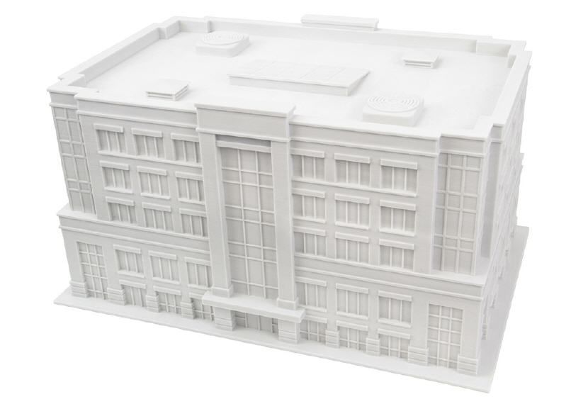 Often, the process of manufacturing a physical layout stretches for months, which disrupts the deadlines and jeopardizes the fate of the entire project.
In the rapidly changing world of digital modeling, relying on hand-made approximations is outdated and costly. Now, if the production of the layout was fast, inexpensive and more accurate, this would open up very wide possibilities! The same 3D model could be directly used in the workflow… Z Corporation 3D printers make these dreams come true.
Visualization
The introduction of Z Corporation's first 3D printer to print 3D physical models brought with it a host of new possibilities. No longer constrained by the high cost and size of prototyping machines, designers began to regularly use visual 3D mockups early in a project.
Morphosis, a Tom Mine Architecture Award-winning company accustomed to working only with cutting-edge technology, was among the first to adopt 3D printing. Morphosis CIO Marty Doscher talks about the company's headquarters in Eugene, Oregon: "We have two 3D printers here, and any project goes straight to 3D from day one. "
"
Tom might do a couple of sketches on paper, but the rest of the work is done in 3D and there are a lot of 3D prints throughout.
Protecting ideas, winning in business
“The human brain works in three dimensions, not two,” explains R. “Partha” Parthasarathy, owner of the iKix architectural bureau. “Architects and contractors have relied on 2D drawings for centuries. But no matter how accurate these drawings are, there is always a danger that the customer will interpret them incorrectly.
As an example, he gives a recent story with a residential complex with hundreds of buildings. The client was quite pleased with the drawings, but as soon as he saw the 3D layout, he was immediately worried about the too dense placement of buildings. To dilute this heap, the architect had to place a swimming pool and a fitness room in the center of the complex. One can only guess how much a belated solution to this problem would have cost the customer — say, when half of the complex would have already been built. .. Having a 3D layout saved the architect a lot of time, and saved the customer from huge expenses for changes in the complex already under construction...
Jerde Partnership purchased ZPrinter 310 Plus printers and now uses them in the development of any project - from a skyscraper to a kiosk. The ability to 3D print in the office allows you to make models very quickly, and in addition, create models that would simply be impractical to do manually.
Visibility: civil 3D printing Scandinavian consulting company Ramboll Group's (www.ramboll.com) has a track record of restored landmarks, stunning bridges, excellent roads and reliable utilities. Nevertheless, each new tender requires not only bright ideas, but also their bright presentation - this is the only way to count on success. This is one of the reasons why Ramboll adopted the Ramboll operates in a highly competitive international marketplace offering a full range of consulting services in the areas of infrastructure, telecommunications, architecture, healthcare, oil and gas, energy, environmental protection, information technology and management. Ramboll is justifiably proud of the design finds already made, but prospective customers are more interested in suggestions for possible future orders. The company is looking for ways to best represent its ideas, and in this area, the possibilities of 3D printing cannot be overestimated. From the very beginning, Ramboll's absolute requirement was color printing. This predetermined the choice: Ramboll purchased a Z Corporation Spectrum Z510 3D printer, the only high-resolution color printer today. The Spectrum Z510 quickly generates 3D architectural and engineering mock-ups in less time and typically at a fraction of the cost of the traditional manual method. Due to the clear color detailing, layouts better convey the ideas of the project. And the ability of the Spectrum Z510 to apply textures to the surface makes the layouts realistic and spectacular, which is especially important for infrastructure projects. For example, Ramboll engineers can apply a brickwork texture to a wall surface, and a real bird's-eye photo of it on a landscape model. New features have significantly increased Ramboll's chances. Shortly after acquiring the Spectrum Z510, the company won a tender to design a major bridge at its home in Denmark. The layout faithfully displayed special V-shaped stops that took up less space and required less material than their classic counterparts. He perfectly conveyed the zest of the concept. “This is just one example where color 3D printing has won a tender,” said Jita Monshizadeh, CAD designer for Ramboll's transportation and infrastructure division. “And we already have many such examples. 3D printing, like nothing else, helps the customer to feel the uniqueness of our projects, not to miss any of the ideas embedded in them. We create presentations that represent the capabilities of Ramboll in high definition and color. The color, clarity and texture, right down to the pattern of the stonework on the wall, really makes a lasting impression.” In addition, 3D printing saves Ramboll money. “Printing a color physical model is almost effortless—provided the right scale is chosen,” continues Jita Monshizadeh. - If the project is made in a 3D design program, this is quite enough to form a 3D model. Sometimes the model needs to be slightly optimized to scale it to the resolution of the printer, but this is usually not difficult. Problems rather arise in the manual production of a layout, when, for example, one single small detail takes a lot of time! In other words, 3D printing encourages creativity and spatial thinking. You can easily make printouts of the layout at different stages of the project and compare them.” |
Just a week after purchase, the ZPrinter 310 Plus helped win the Jerde Partnership's San Diego Coastal Landscape project.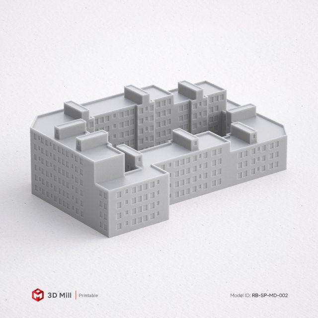 The detailed physics model showed how the Jerde project enhances the contours of the landscape while maintaining its overall style. Al Waas, deputy vice president and chief designer of the project, says that creating the same layout by hand would require a week of effort from an entire team of specialists. And with the help of the ZPrinter 310 Plus, the layout was printed in just half a day. “The more detailed the project, the more complex it is, the more benefits 3D printing provides,” Vaas notes. And he adds that the use of 3D printers gives an approximately twofold increase in productivity.
How it works
Z Corporation's 3D printers work with BIM file formats to create 3D physical layouts from composite powdered plaster.
Z Corp cuts a model from software such as Autodesk Revit or Autodesk 3ds Max into thousands of horizontal layers. The printer's print head then makes thousands of passes through the powder, leaving a liquid binder at the intersection points.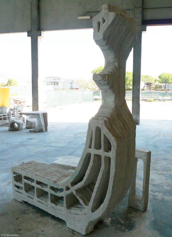 Where this substance comes into contact with the powder, the latter quickly hardens. Thus, printing at a vertical speed of about one inch per hour, the printer deposits the material layer by layer and creates a finished layout from powdered plaster.
Highlight: Using 3D layouts in presentationsFor Robin Lockhart, Associate Manager and Chief of Operations at OBM International (www.obmi.com), design projects that used to take hours of discussion and lots of trial and error decisions are now the catalyst that sets the overall momentum. The thing is that not so long ago the company integrated 3D printing into its production processes. One of the very important projects is the construction of the new headquarters of OBM International in the city of Coral Gables. “Using a 3D printer purchased from Z Corporation, I made a mock-up of a four-seat workbench with components broken down so that they can then be assembled in different configurations,” says Robin Lockhart. OBM International acquired a Z Corp Spectrum Z510 3D printer in December 2007. “Now we use the Z Corp Spectrum Z510 with all the options, including the automatic cleaning module for powder residue. In essence, we have here the entire set of devices for working with layouts, which gradually developed around the main printer. Lockhart commented that 3D printing had the best impact on the nature of OBM International's business: “Our level of understanding with the customer is amazing. The general mood of the presentation instantly changes for the better as soon as we present the layout to the customer. Clients are now able to discuss in a way they understand well, the model consistently makes a good first impression, and clients are grateful. Previously, OBM International used traditional 2D drawings, color projections and videos for presentations. Designers used tracing paper, hand sketches, CAD, 3D visualization and modeling. “All this was in our arsenal, and all this imposes certain restrictions. When we make a presentation for a customer who is not fully familiar with the nuances of this format, the information content is reduced, and this can negatively affect the decision made.” According to Robin Lockhart, OBM International also makes 3D models for its own needs: for the purpose of critical analysis and evaluation of the project. “Our document workflow is focused on the ubiquity of physical layouts,” says Lockhart. — With more and more active use of the 3D printer, we can hope that the quality of our projects will only improve. In addition, this device really became the highlight of all our architectural presentations.” |
Z Corp 3D printers are unique: only they can make models in color.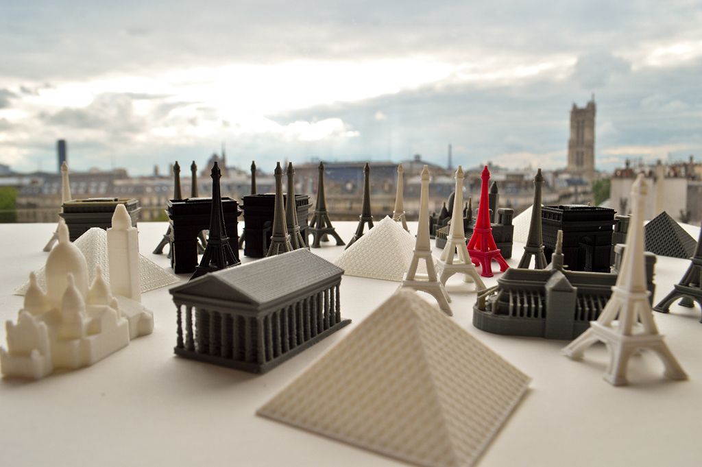 No other technology for creating 3D layouts provides such an opportunity. In addition, graphics and photographs can be applied to the model to further enhance the resemblance to the original.
Z Corp software allows you to go beyond the size of the build area. The layout of the building can be divided into parts, and ZEdit Pro will automatically add studs and holes to them for subsequent assembly almost flush.
Savings
While a handmade mockup can cost thousands of dollars, the same 3D printed layout from Z Corporation costs only $2-3 per cubic inch.
“For medium to large projects, the cost of making a mock-up pays off almost immediately,” said Scott Harmon, Vice President of Development at Z Corporation. — Often, the device itself pays off very quickly — for example, if at the very early stage of the project, thanks to the model, it was possible to detect a serious error or the company became the winner of the tender, presenting its project in the most advantageous light.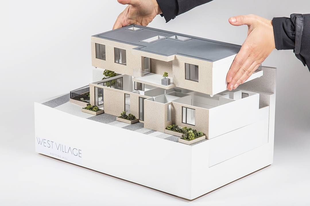 While 3D building layouts are relatively new, the majority of our clients are architects, who get value from the printer from day one.”
Speed and scalability
Where it took weeks to produce a medium-sized layout, a 3D printer can do it in less than 12 hours. Z Corporation inkjet 3D printers do not smoke, produce a minimum of waste, and the material remaining unused during the printing process is suitable for further use. Printers print at resolutions up to 600 dpi, scrupulously reproducing the smallest surface details.
The Z Corp line includes the ZPrinter 310 Plus black-and-white printer and three color devices: the ZPrinter 450, the Spectrum Z510, and the high-resolution ZPrinter 650.
it’s impossible to print models one on top of the other,” says Scott Harmon. “Z Corp printers are able to print as many layouts as they physically fit in the build area by having a thin layer of powder between them.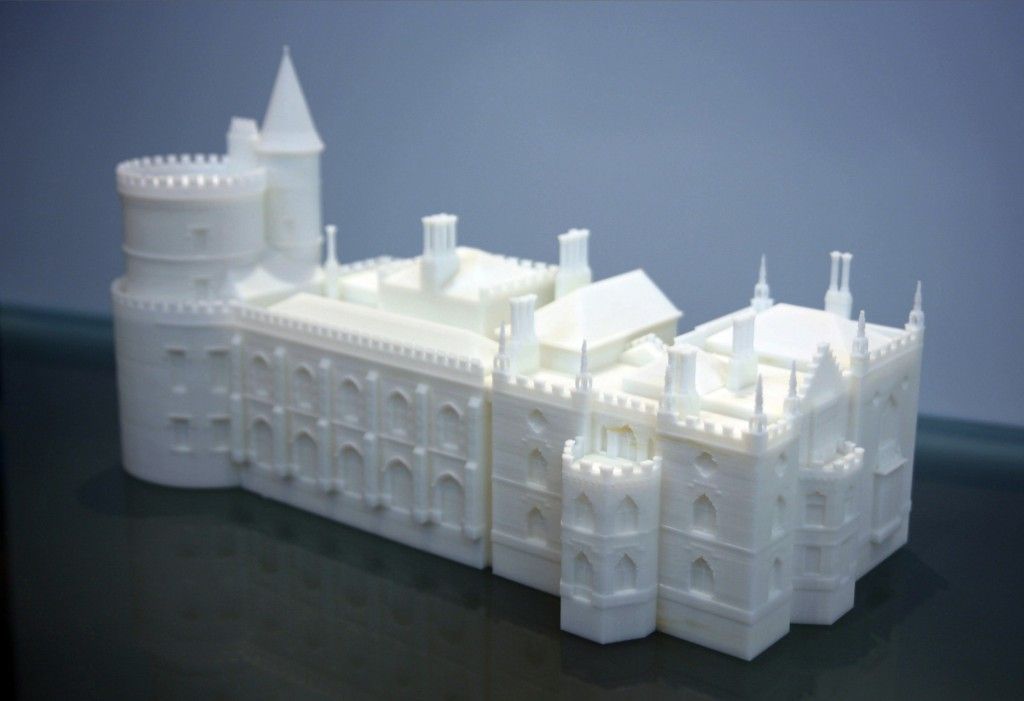 ”
”
Export from Autodesk RevitThe increasing use of 3D printing in architectural design has resulted in a tool that allows users to upload STL files imported from Autodesk Revit directly to a Z Corp. 3D printer. Not so long ago, Autodesk announced the release of a new STL Exporter utility for the Autodesk Revit 2009 (BIM) platform. In the past, converting Revit files to STL format required third-party software. This development highlights Autodesk's confidence in 3D printing and its growing adoption as the process becomes more cost effective and efficient. "Physical 3D models are becoming an integral part of the design process, offering visual insight into the design and improving the relationship between designer and customer," said Emile Kfoury, Senior Line Manager at Autodesk AEC Solutions. — 3D mock-ups are necessary for our customers throughout the entire life cycle of a product, but primarily when searching for a conceptual solution. Emil Kfoury also noted that he is confident in the bright future of 3D printing. “Most of the 3D models are still printed only at the stage of conceptual development — during the study and design of the outlines of the future building. In addition, the physical layout appears at the final stage, even when the project is released to the public. In the future, I see 3D printing at all stages, when the smallest changes are reflected in a separate layout and studied in order to make sure they are necessary. I expect that color and textures will be more and more in demand in layouts - they make the model extremely visual. The STL Exporter converter, which generates an STL file from a model created in Autodesk Revit Architecture, Autodesk Revit Structure and Autodesk Revit MEP programs, is available for download on the Autodesk website (www. |
Not so long ago, the Realization Group was once again convinced of the benefits of mass printing on Z Corp printers. When its office in Coral Gables, Florida, ordered 100 copies of the layout for marketing purposes, Realization Group was able to complete the order in just two days—thanks solely to its ability to print multiple copies at the same time with no loss in accuracy, quality, or reliability.
Along with the benefits of speed and affordability, a 3D printer is of particular value to aspiring architects. The use of 3D printing at an early stage of design allows you to quickly gain valuable experience, protecting both the architect and customers from costly mistakes caused precisely by a lack of experience.
Thanks to Z Corporation's 3D printers, which produce architectural models much cheaper and faster than by hand, 3D printing can now be applied early in the design process, making the entire process more efficient.


 "Parta" Parthasarathy greets a new client with the same question: "What problem can we solve for you?"
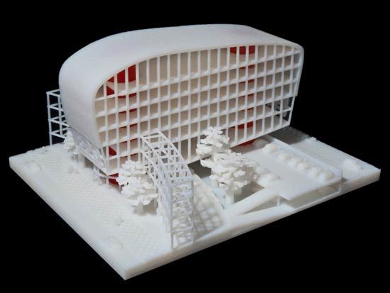
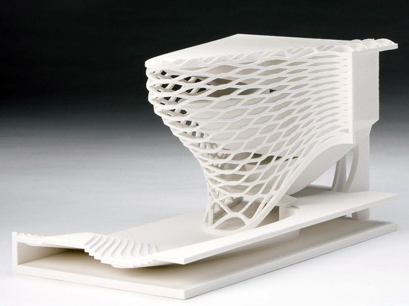 I sincerely believe that all architects will work in 3D. Clients come to iKix to implement more and more new projects in three-dimensional layouts. The benefits are undeniable."

 For example, when a company recently needed a mock-up of a 12-story residential building, it was calculated that printing a color model on a 3D printer would cost three times less than ordering it manually.
 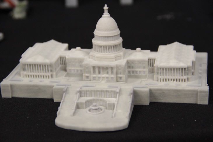 — The design team offered solutions that can be combined by swapping components. This saved us from unnecessary debate, saved a lot of time and effort, and most importantly, it allowed us to quickly come to the desired solution. In addition, the search process itself turned out to be extremely exciting.
 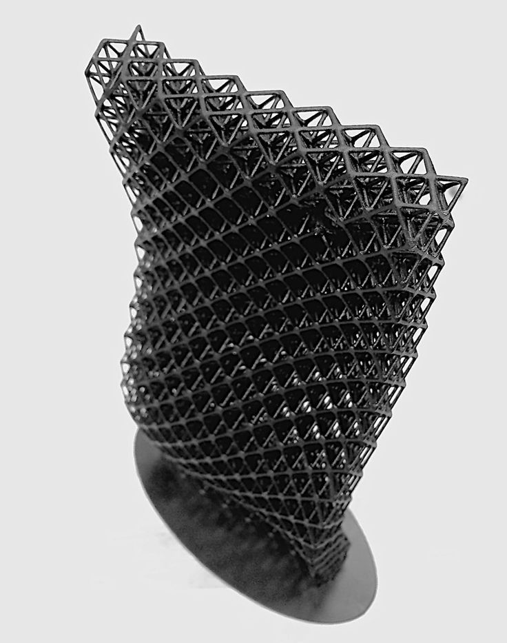 ”
”  The STL Exporter for the Revit platform has full support for Z Corporation devices, which have made 3D printing not only incredibly fast and high quality, but also truly affordable. We are also developing other interesting solutions for printing physical layouts on Z Corporation printers.”
  autodesk.ru).