3D printing how to design
What software to use for 3D printing: The complete guide
David Roberson13 May 2021
Guide
Before starting to 3D print, you will need to make sure you have gathered all the necessary software “ingredients” that will guide you through the printing process, from preparing your 3D model to managing printers themselves.
These include:
CAD software to create a 3D model (you can also use an existing 3D model, if you do not wish or need to design one)
Slicing software
Software to operate your printer remotely (this is optional, but can be convenient)
This article will go through each of these ingredients, and will also touch on how the Ultimaker platform creates a seamless end-to-end flow between hardware, software, and materials, empowering you to unlock the magic of 3D printing and make innovation happen.
What is a “slicer”?
A 3D printing slicer – also known as slicing or print preparation software – is a program that converts a 3D model into a language your 3D printer understands.
Slicing software, such as Ultimaker Cura, digitally cuts a model into flat layers, which your printer can then print one by one. With the Ultimaker platform, however, slicing software is not always needed, thanks to integrations that allow you to print directly from CAD or the Ultimaker Digital Library.
Preparing a 3D print using Ultimaker Cura software
What is the best CAD software to design 3D prints?CAD, or computer-aided design, software enables you to design a 3D model from the ground, up. There are many types of CAD software, each with its own benefits. AutoCAD, created by Autodesk, is perhaps the best-known among them since it was one of the first CAD software programs available for personal computers when released in 1982. Other CAD platforms include:
Fusion360 – great for designing and creating efficient mechanical parts
3ds Max – used in all types of 3D model creation, including video game design, architecture, and 3D printing
TinkerCAD – A free, browser-based CAD tool that allows users to build 3D models out of various shapes.
 Popular with CAD novices and for STEAM education
Blender – free, open-source 3D model creation software
Siemens NX – for designing and creating advanced 3D models
Solidworks – for designing and creating professional parts for industrial use
Catia – Advanced design software used for creating surfaces and engineering systems
Before you begin 3D printing, be sure to do your research and pick the CAD software that’s right for your use case. This way, you’ll get the most out of the model you choose to design and print.
Also check which file types your slicing software is compatible with, so you can make your 3D designs into 3D prints.
A design in CAD software (left screen), slicing software (right), and the finished print
How to design parts for 3D printing?
When designing for 3D printing, there are best practices to help you get the best results from your 3D printer and the parts it creates. Design parts optimized for 3D printing will improve print success rates, reduce costs through lower wastage, and boost the speed of your product development cycle.
Consider build volume. Your 3D prints can only be as large as your printer’s build volume. Be sure to know its dimensions, then create a part that can either be printed within those dimensions in one go, or plan to use modularity (printing then combining separate parts).
Decide orientation early. Because FFF prints layer by layer, determining the print orientation early in the process helps drive design choices, text alignment, and snap features.
Evaluate overhang support requirements. FFF printed parts are self-supporting up to 45 degrees. Overhangs below 45 degrees must be supported from below with support material.
Follow bridging support guidelines. For most basic filaments, FFF printing does not need support when bridging materials within a 10 mm gap.
Pay attention to nozzle size. When designing small features, you should consider height, wall thickness, and nozzle size. Larger nozzles will print faster than smaller nozzles, but at a cost of increased minimum thickness and height for your models.
Design with hole diameters in mind. Generally, 3D printed hole features should not be smaller than 2 mm. If accurate holes are required, it is recommended to design the holes smaller than intended and post-process with a drilling operation.
Avoid sharp corners. Sharp corners can be modelled in CAD, but the print may warp. Increasing the area of the surface in contact with the bed will decrease the likelihood of the warpage.
For a deep dive into these factors and more, check out our blog on design for 3D printing.
What software do I need to start a 3D print?
This depends on how much of the 3D printing workflow you need to perform.
As long as you already have access to a 3D model, you will typically need software that can slice that model, so your printer can get to work. Once you have started to print, you can also use software to manager your 3D printer (or printers) remotely.
But as we saw earlier, the slicing step can be avoided if you have a 3D printer integration installed in your CAD tool. If you already have access to a 3D printable file (such as a G-code on a USB stick) you can also go ahead and print without the need for any slicing software, as your digital file is already ready to print.
Controlling 3D printers remotely with Ultimaker Digital Factory software
Managing 3D printers remotely
Ultimaker S-line printers, the Ultimaker 2+ Connect, and the Ultimaker 3 can make use of a network connection to access cloud-based services on Ultimaker Digital Factory. By linking a printer to your Ultimaker account, your printer can then be controlled remotely, from outside of its local area network.
Want to learn more about 3D printing software?
Download our free white paper, “Important 3D printing software features,” which will help you determine the best 3D printing software for your business needs, as well as examine settings, print profiles, and other features that can help you get the most out of your printing experience.
Get the white paper
What are the key design elements for 3D printing?
Are you new to designing parts for 3D print manufacturing or need a refresher on essential design elements? This article provides the key design elements for creating digital models for 3D printing, no matter the additive manufacturing process.
Every 3D printing technology comes with a distinct set of capabilities and its own design freedoms and restrictions. Whether you are a seasoned engineer who’s well-versed in designing for 3D printing or you are new to the field, it’s always a good idea to go over the most essential factors that make or break a design.
This article covers the key design considerations that apply to 3D printing in general, regardless of the printer you choose for manufacturing your custom parts.
Check out this handy infographic for quick access to every essential design element you may need while creating digital models to 3D print.
Each 3D printing process has its own design advantages as well as some limitations. Let’s break down the key design considerations that apply to every 3D printing technology to keep in mind when designing your next custom parts.
All 3D printing processes build parts layer-by-layer. New layers can’t be deposited onto thin air, so every layer must be printed over some underlining material.
Overhangs are areas of a model that are either partially supported by the layer below or not supported at all. There is a limit on the angle every printer can produce without the need for support material. For example, if you’re printing with an FDM and SLA machine, this angle is approximately 45 degrees .
We recommend limiting your model’s overhangs, as layers printed over support structures usually come out with a rougher surface finish.
This image shows the effect of increasing angle on overhang quality for FDM printingWall thickness for 3D printing
The second thing to keep in mind when designing a part to be 3D printed is wall thickness. Every 3D printing process has its own level of precision. FDM, for instance, is the least accurate, while SLA has the tightest tolerances. In terms of part stability, every 3D printing process has a lower limit regarding wall thickness and feature size.
For example, imagine you are an engineer designing a new generation of hang gliders. You’ve chosen to 3D print a scaled-down version of the product to test its efficacy. 3D modeling programs allow you to model the sailcloth of the wing, for instance, but you then encounter problems when you would try to 3D print it. This is because the model’s wall thickness is less than the minimum required for successful printing.
It’s essential to make sure that your 3D designs have walls that meet the minimum required thickness for the printing process you choose. All 3D printers can successfully print components with wall thicknesses greater than 0.8 mm.
What is warping and how can you avoid it?
Something that is often easily overlooked while designing a 3D model is the fact that the materials used for 3D printing undertake physical change: they are melted, sintered or scanned with a laser and solidified. The heating and cooling of material can cause the parts to warp while printing.
Large, flat surfaces can be especially prone to warping. Warping can typically be avoided by using correct machine calibration and having adequate surface adhesion between your part and the print bed. A good practice is to avoid large flat surfaces and add rounded corners to your 3D models.
When you are creating a 3D model with intricate details, it is important to keep in mind the minimum feature size each 3D printing process can handle. The minimum level of detail is connected to the capabilities and mechanics of each 3D printing process and to the selected layer height .
The process and materials used will have an impact on the speed and cost of your print, so determining whether smaller details are critical to your model is an important design decision.
The most important thing to remember while designing for 3D printing is the fact that your digital design will become a physical object. In the digital design environment, there are no laws of physics to adhere to, such as gravity.
Anything can be "drawn" in 3D on a digital canvas, but not everything can be 3D printed. Knowing the key factors that go into designing 3D models will ensure that you produce digital designs that can be successfully printed.
Want to learn the key design elements for every 3D printing technology?
Design parts for FDM Design parts for SLA Design parts for SLS
Ready to transform your CAD file into a custom part? Upload your designs for a free, instant quote.
Get an instant quoteHow to design and 3D print snap-on enclosures
If you are a product designer or engineer, at some point you may need a custom enclosure design. This could be a simple container to organize small items, or a fully working 3D printed prototype for demonstration to interested parties or testing before moving on to injection molding.
Using CAD software and desktop 3D printers, you can create an enclosure with interlocking latches in just five easy steps.
Technical report
How do you create your own cases with exact dimensions? Learn more about stereolithographic 3D printing by reading our free white paper Introducing Desktop 3D Printing with Stereolithography.
Download white paper
Measure your electronic component (left). Begin your 3D model with basic boxes (right).
Measure electronic components (left). Start building your 3D model with the standard boxes (right).
In this project, we will create a case for a Pine 64 single board computer (download the STL file from the Pinshape website to repeat the steps on your hardware). In this article, we're using SolidWorks, a popular design and development software, but you can use a similar 3D design software.
First take a digital caliper or ruler and measure the electronic components. We like to start case design by accurately reverse engineering the PCB, determining its dimensions, mounting hole locations, and any connectors or plugs that will need to be accessed through the case.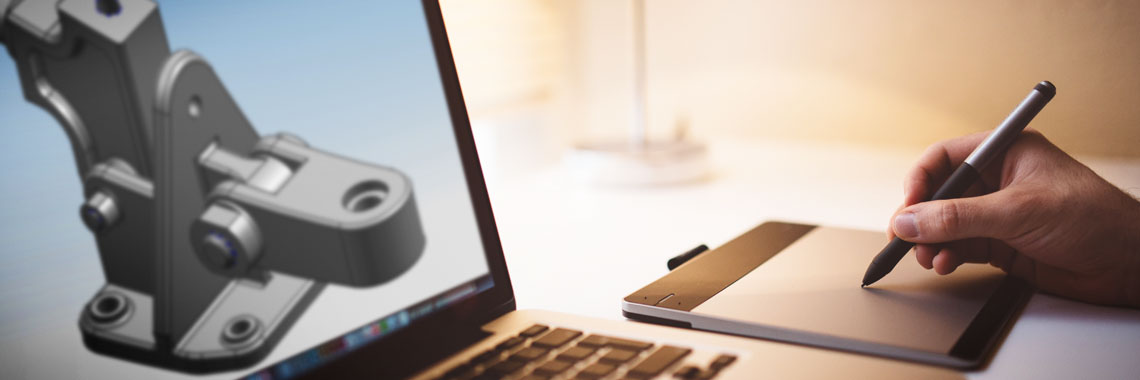 You might want to just measure the maximum box dimensions, but it's important to know exactly where the main components are so they can be placed correctly. Reproduce these measurements in SolidWorks by laying out the boxes in a single model file.
In SolidWorks, an enclosure is best designed as an assembly model, designing the halves as separate parts. Create a new part that will be the base of the body. The first important decision to make is to determine how much distance is allowed between the PCB perimeter and the package. It depends on the 3D printing technology you are going to use. 3D printers based on SLA and SLS technologies are highly accurate, so you can safely set a tolerance of 0.5 mm.
Desktop 3D printer based on FDM technology can deform your structure and lift it off the platform, so you need to allow for a higher tolerance of 1.5-2 mm. This will guarantee the placement of the printed circuit board in the case, even if its walls are slightly deformed.
Check out our detailed guide comparing FDM vs. SLA 3D printers to see how they differ in terms of print quality, materials, application, workflow, speed, cost, and more.
Leave a space between the edges of the electronic component and the housing (left). Create the walls of the bottom of the hull in the 3D model (right).
Next, you need to make holes for the connectors. One common mistake is to cut a hole just large enough to access the connector, be it USB or HDMI, without considering that the many cables around the plug connector can be quite bulky and have to be inserted into the case to connect to the connector (especially if the connector is on a printed circuit board). board is at a greater distance from the case). Therefore, it is better to make larger holes for connectors. You can add from 2 mm around the perimeter.
Add cutouts and holes to the bottom of the housing for the connectors.
As you can see in the image above, we've included cutouts that go all the way to the top of the part and one hole for a Micro SD card.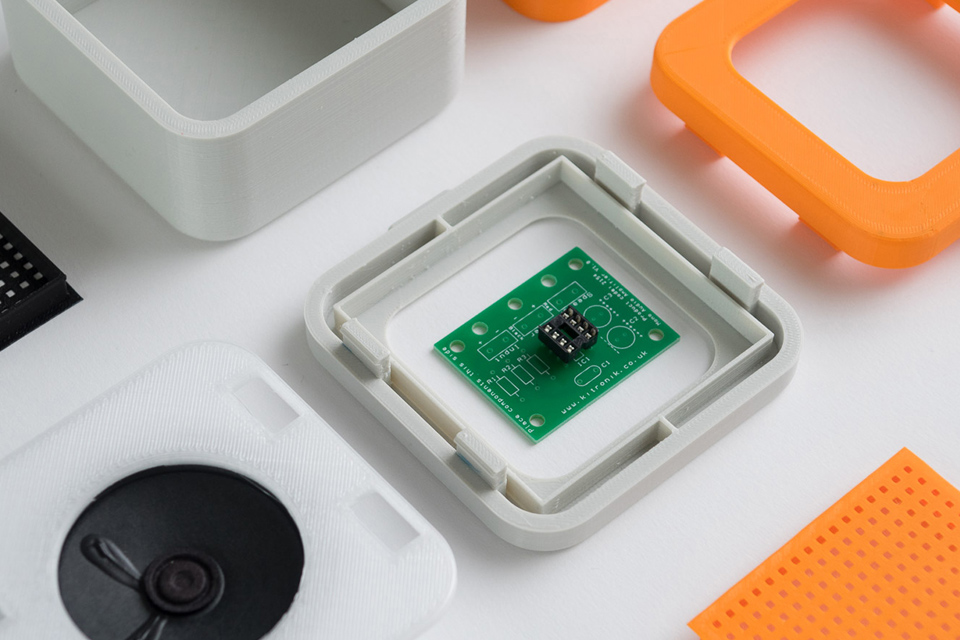 Some of the cutouts reach the top of the part because the connectors on the PCB protrude beyond the edges of the part, otherwise the board would be very difficult to fit into the case. Some of these cutouts will be covered by the top half of the case, but you can make the bottom half larger to accommodate the entire PCB and connectors. Just keep in mind that you will have to insert the connecting cables deep into the case.
As a rule, the shape of the upper part of the case mirrors the shape of the lower half.
If you have finished designing the bottom part, you will have no problems with the top one. The image above shows the effect of a decoupling line running along the perimeter between the two body halves. The top of the case should have similar cutouts for tall connectors, and more material where it meets some of the cutouts in the bottom half. In addition, we have added an additional recessed part in the middle.
White Paper
Tolerance and fit design reduces post-processing time and simplifies assembly, as well as reduces material costs per iteration.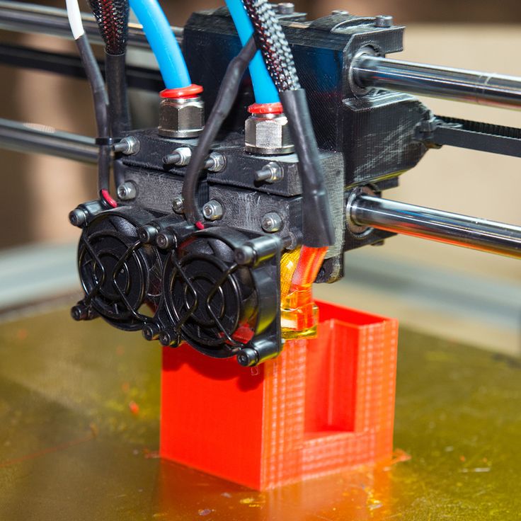 Download our white paper to learn more about tolerances and fit in 3D design and production models.
Download white paper
The standard internal cantilever latch allows the lock to be extended for a stronger hold.
From a variety of snap-on component designs, we settled on a standard internal cantilever connection. The image above shows the main parts for the interlock, absolutely identical on both halves of the housing (male and female components). Depending on the working space available, the small protrusion inserted into the lock cavity can be lengthened to improve grip. In our model, its length is only 1.2 mm, but with a length of 2 mm, the lock would be much more secure. In this particular design, the pins on the PCB take up a lot of space, so the lock is designed to simply push in while still providing enough force to secure the case. The console connection has a 20 mm protrusion, which increases its reliability.
This sectional view shows details of the lock on both sides.
The illustration above shows the components of the locking joint and the location of the pins (in black) on the PCB that limit the size of the cantilever joint. Instead of placing the snap-on elements inside the lower housing, it is also possible to place the protrusions in the through holes, which will increase their length.
The tabs are small protrusions that are inserted into the opposite side of the case, fixing both halves.
Add petals to your design to keep the halves from slipping. Petals are small protrusions that are inserted into the opposite part of the body. Since we have created two interlocks on opposite parts, they will only be needed on the two sides where there are no interlocks. This case is large, so we put them in every corner. The material protrudes only 3mm, but that's enough to prevent movement of the 3D printed parts that have been bonded.
This standard lockable housing can be adapted to almost any small electronic component.
While this may be enough for your project, a few extra details will help bring your 3D case to life.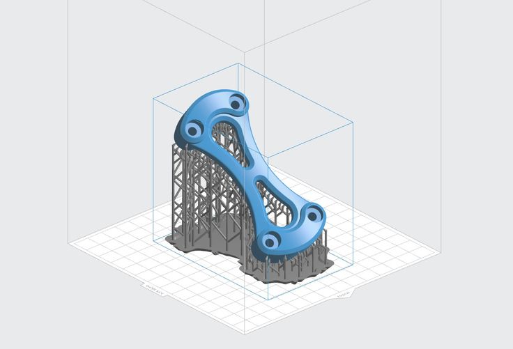 We added indented text to this project for the Pine 64 name and details such as the SD card slot. We added the Pine 64 logo not only for beauty, but also for ventilation, as these boards can get hot. In addition, these parts save material used for 3D printing. Finally, a pair of embossed lugs next to the latch connections help you determine where to push to open the case.
The final design of the snap-on case incorporates all of these unique features and is ready for 3D printing.
Stereolithographic 3D printing allows you to create accurate models and prototypes from a wide range of engineering polymers, reducing costs, speeding up development cycles and raising market standards.
Want to see what you can print with a stereolithographic 3D printer? We will send a free 3D printing sample directly to your office.
Request a free print sample
quick tips for moving from CAD to printed was withdrawn from publication due to a technical error. Please be understanding.
 Thank you!
 Whether it's just a hobby or a source of income, 3D printing is always based on product design. Those accustomed to traditional technologies will have to rethink the entire approach to product design and manufacture.
When the project is ready, a number of additional operations are performed: setting the orientation of the model and other parameters that ensure the proper printing process. In addition, it is necessary to take into account the fact that most 3D printers allow you to choose the degree of filling the model with cellular structures. The correct choice of this parameter provides protection of the object from deformation and destruction during the printing process, as well as significant savings in material and reduction in production time.
Finally, the last factor influencing the success or failure of the 3D printing process is the strength of the connection between the model and the table. If the workpiece is separated from the table during printing, then all the work will go down the drain.
Here, we'll walk you through the 3D printing process and give you a few simple tips for using the power of additive manufacturing in the design phase. In addition, we will dwell on the methods of preparing a finished project for printing, and also consider ways to securely fasten the workpiece to the table.
These guidelines apply primarily to Fused Deposition Printers (FDM) printers, but may apply to other types of printers as well. The process of obtaining a finished part by 3D printing is basically the same regardless of the method used.
Designing an object
Any 3D printing starts with construction. If you are developing a product yourself, then you need to build a 3D model of it in a computer-aided design (CAD) system to turn the designer's idea into reality. In this case, the object can be both very simple and very complex. However, too thin and too small models should be avoided.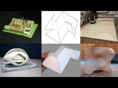
3D-CAD from Siemens from this article for 49900r (90% discount), the promotion is valid until March 20, 2020. Read more>>
Saving the file in a special format for printing
To print an object, its model must be saved in a special file format - for example, STL, which has become the de facto standard in the world of 3D printing. In this format, model surfaces are represented as a grid of triangles. Simple surfaces are broken down into a small number of triangles. The more complex the surface, the more triangles you will need. Today, other formats are used in 3D printing, in particular, the 3MF format developed by Microsoft. But the most common is still STL.
CAD-systems make it very easy to save the model in the desired format: just click the Save As command. To improve print quality, it is desirable to set a number of settings for saving to the STL format - for example, the tolerance during transformation and the angle of the plane. The lower the conversion factor and the better the angle, the smoother the printed part will be.
Opening the file in the slicer program
Most, if not all, 3D printers come with their own slicer software. The slicer loads the STL file created in the CAD system and cuts it into layers, and then creates a control program for the printer.
Positioning the model correctly in the print space
After entering the print settings, the model (or several models) needs to be placed on the printer table. You can print many objects on one table at once. At the same time, compared to printing a single object, the time slightly increases, but in general it still turns out to be less. Here are some tips for choosing the right model orientation.
Set parameters
In the slicer program, the user sets parameters such as print speed, material consumption, nozzle and desktop temperatures.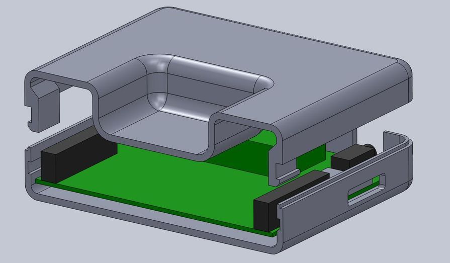 Most slicers have simple settings for beginners. In this case, most often there are also advanced settings so that experienced professionals can achieve optimal results. Advanced settings include percentage infill, amount of backing material, and type of backing or raft (this is a small, thin base that keeps the printed part stable. The backing is removed when it's finished). The number of options is truly endless. Specific settings vary depending on the brand of printer. It's easy enough to set them up.
Sending the control program to the printer
After setting the print settings, the placement of future objects on the table, their orientation and quality, it's time to finally start the printer. It is enough to press the Print button and find something to do while the production is in progress. Depending on the complexity of the design, the process takes from several minutes to several hours.
Finishing
Finishing includes removing the printed part from the table, as well as removing the support material by melting, mechanical separation or dissolution (depending on the design of the printer).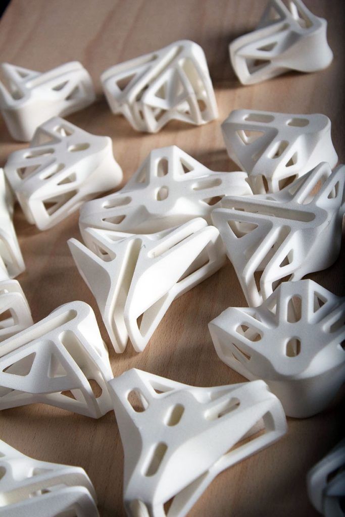 The part may require some light sanding or polishing, but overall a properly printed object looks good from the start. Other types of finishing are placing plastic parts in a container with acetone to smooth out surface roughness, gluing (if the dimensions of the structure exceed the dimensions of the 3D printer or individual elements of the object must have different orientations), drilling holes and painting.
3D printing process
3D printer design considerations
Eliminate sharp corners
If the direction of the surfaces changes abruptly (for example, a vertical wall intersects with a horizontal overlap), then such a model is difficult to print. The printer will build excessive inner surfaces, wasting too much material. There are two easy ways to prevent this: add chamfers to smooth out where the surfaces meet, or round the corners so the printer gradually builds a vertical surface. In addition, rounding will increase strength, since destruction most often occurs at sharp corners.
Elimination of thin walls and small geometries
Layer by layer fusing technology consists in supplying hot plastic through a nozzle with the formation of a printed object layer by layer. The thickness of the extruded plastic layer cannot be made smaller than a certain limit, depending on the diameter of the nozzle and the speed of the print head. Excessively thin-walled details are difficult to print - often the result is a chaotic weave of fibers. If the part can be printed, it is very fragile and breaks easily.
Too thick walls - also bad
On the other hand, if the walls are too thick, they become brittle and crack easily. This is especially important when printing from materials other than resins, as excess thickness during the manufacturing process leads to internal stresses in the part.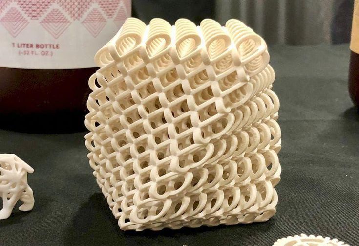 Even when printing from plastics, material is wasted on walls that are too thick and time is wasted.
Removing large overhangs
3D printers allow you to create amazing shapes and surfaces, but they are not capable of printing directly in the air. If there is a void in the part with material above it, additional support material must be used. Most slicers add material automatically, but require you to specify the orientation and volume of the support structure. Printers with a single nozzle create an array of thin columns, which then have to be broken off. The result is an uneven surface. Therefore, it is recommended to avoid large overhanging elements whenever possible in order to reduce the need for support material.
If such an element is unavoidable, you can try to flip the object. Most printers are capable of printing overhanging elements with an angle of about 45 degrees. At a certain height, the edge of such an element may sag somewhat. The actual capabilities of a particular printer are determined by trial and error.
Holes shrink
Remember that the part is made of heated plastic. As it cools, it inevitably shrinks. Therefore, holes and other critical structural elements have to be made larger so that after shrinkage their size is as close as possible to the required one.
However, if a tight tolerance hole needs to be made, it is better to print it in a smaller diameter and then ream it with a suitable tool. This is especially true for holes whose axis is parallel to the printer table.
Increasing the footprint
If the area of contact between the object and the base is small, the part may separate from the table during printing. To prevent this from happening, wide bases are added to the model legs, which are installed on the printer table. In general, the closer to the table, the more material must be added to the support.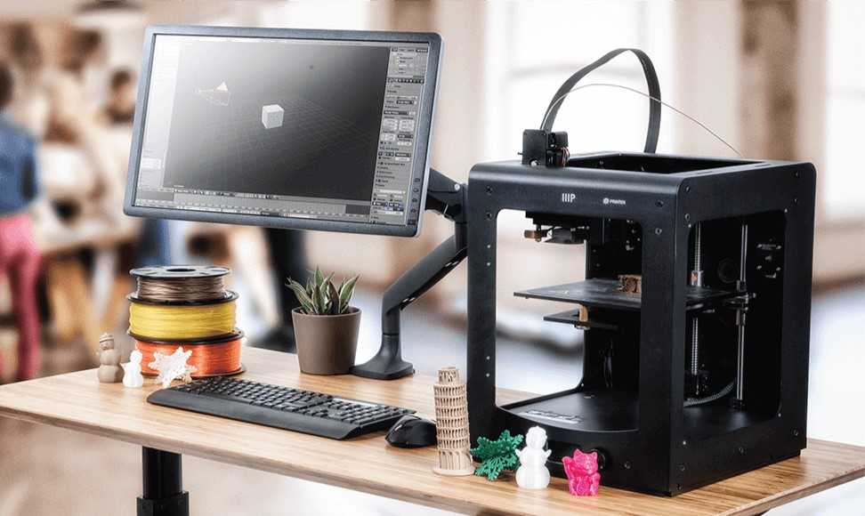 There are other ways to securely fasten the part to the table, which we will discuss a little later.
Special moves
The right approach to design makes printing easier. In addition, there are special post-processing techniques that are important to be aware of.
Arrange round surfaces vertically
The model should be oriented so that the minimum amount of support material is used. Ideally, it should rest on the table with a large flat edge. In addition, circular geometry must be placed so that the circular faces are vertical. If we look at the printer table from above, we should see a round silhouette of the object. In this case, the part comes out as symmetrical as possible with the formation of a solid round structure.
Place voids and holes vertically
If there are voids in the model (for example, it is a rectangular pipe), it is desirable to place such voids vertically in order to reduce the volume of the support material. If you print the pipe in a horizontal position, you will have to provide support for the entire inside. If you put the pipe on the end, then no support is required at all.
The same is true for holes: to get a hole with a straight axis, it is best to print it vertically - in the form of a stack of rings, which avoids warping or deforming a round hole into an oval one.
Set print quality settings
Proper selection of print parameters, such as STL conversion tolerance and slicer software settings, allows parts to be produced with a surface quality that matches that of cutting. However, this entails an increase in print time. When choosing quality parameters, one should proceed from the purpose of the object: is it a finished product or a prototype? Will the part be visible or hidden?
The quality parameters also affect the shape of the holes in the part. In CAD files, holes are represented as a set of straight lines at an angle to each other.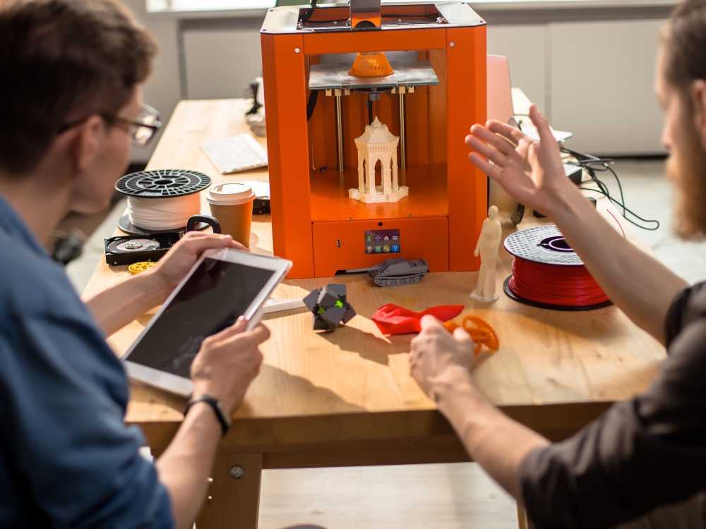 The higher the quality of the model in the saved STL file, the less the circle looks like a polygon.
Reducing the layer thickness
To obtain the best quality, especially when using layer-by-layer deposition technology, it is necessary to reduce the thickness of the layers. It does increase the print time, but the end result is worth it!
Optimizing the filling with honeycomb structures
In terms of strength, objects do not have to be solid. Similar to a honeycomb, printers can create a honeycomb infill that balances strength and saves expensive polymer material. However, if the printed part serves as a prototype for strength testing, and the serial product will be manufactured by traditional methods, and also if the part is subjected to certain types of mechanical stresses and pressures, a solid design will be preferable.
Choosing material
The success of printing largely depends on the correct choice of material.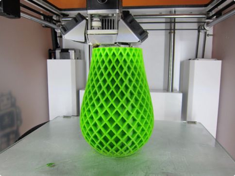 Materials have different properties. For example, the melting point of thermoplastic polyurethane (TPU) and polylactic acid (PLA) is lower than that of acrylonitrile butadiene styrene (ABS). In addition, the material is taken into account when choosing the type of support structures. For an object made of polylactic acid, supporting elements can be made from the same polylactic acid, since it will be quite easy to separate them from the finished part. If the part is printed from ABS plastic, then the support elements must be made from a different material, and it is better not to use such elements at all in thermoplastic polyurethane parts.
Cellular filling
A solid body is not always the best choice for 3D printing. Printing solid parts has its advantages, but the internal honeycomb structure saves both expensive material and time.
Creating objects with a specified degree of filling with honeycomb structures is a unique opportunity for 3D printing.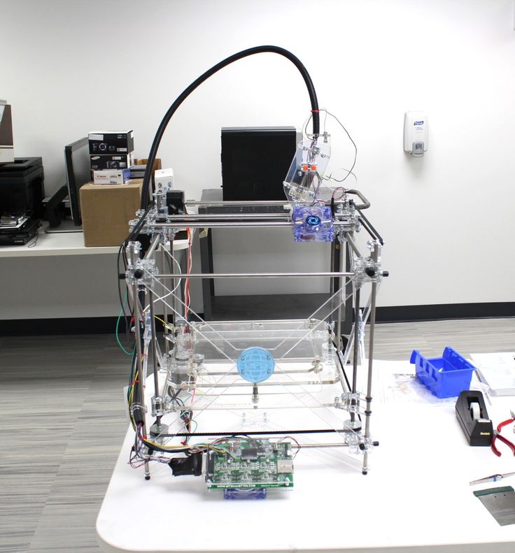 Moreover, it is not required to design such a structure: this is done by the slicer program. As a rule, it is enough to set only the percentage of filling (the closer it is to 100, the more solid the object will turn out) and select the type of cells, if the printer has such an opportunity.
In addition to saving time and material, the internal honeycomb structure has many other advantages.
Cellular filling prevents warpage
Printing large objects as a single piece introduces a danger of warpage. By reducing the infill percentage, the air during printing passes through the part, providing more uniform cooling and eliminating warpage.
Cellular filling does not lead to loss of strength
Printing cells instead of solid material does not reduce the strength of the part. In many cases, a honeycomb part is strong enough for the chosen application, but lighter and less material intensive.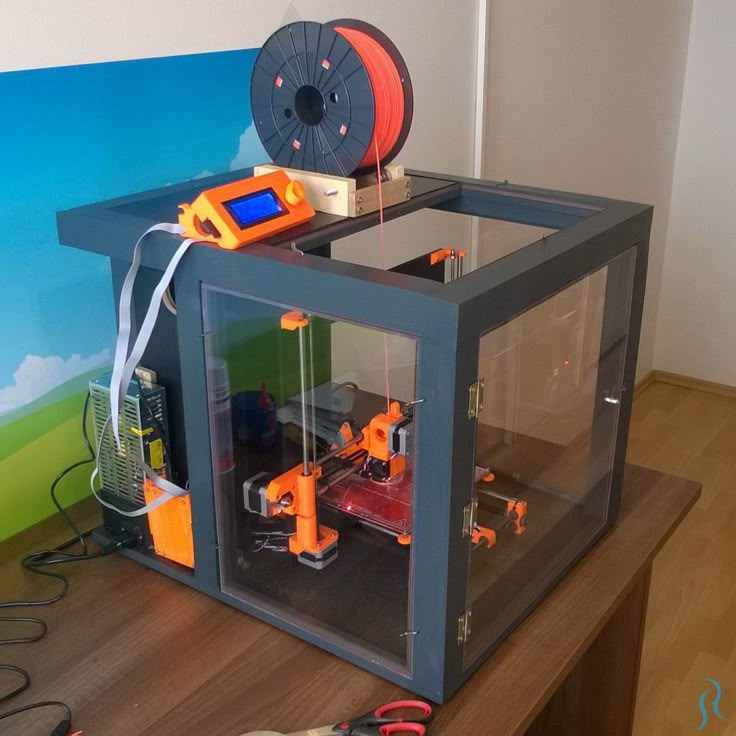
The function determines the selection of cell geometry
Most slicers support a wide variety of cell geometries. The optimal option is determined by the functional purpose of the object. Standard box padding simplifies printing, while hexagonal and triangular boxes add strength. Wave fill allows the object to bend or twist.
How do I choose the right filling percentage?
In general, the strength of an object increases as the percentage of infill increases. Most printers have a default infill percentage of 20, which is optimal in some cases but too high or too low in others. Consider mechanical stresses in the printed object and increase the percentage of infill in areas where greater strength is required. If high strength is not required, choose the lowest possible filling. This saves material and speeds up printing. Most often, the selection of the optimal percentage of filling is done by trial and error.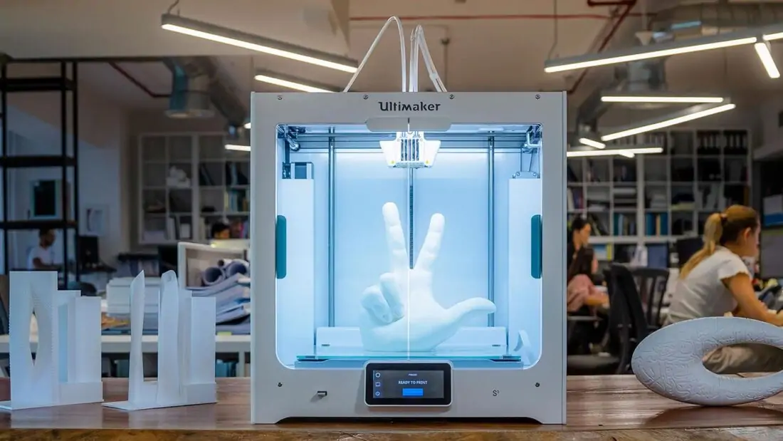
Ways of fastening the workpiece to the table
“Rafts”, “brims”, “skirts” – these terms sound funny, but they just refer to the three main ways of attaching a 3D printed part to a printer table. Let's take a look at each of these methods and their areas of application.
Skirt
The skirt involves creating a few rings around the object at the beginning of the print to make sure the plastic is extruded normally. The skirt is not in contact with the object at all. It surrounds the printable area and helps start the fusing process. When creating a skirt, a large volume of hot thermoplastic polymer passes through the nozzle. This prepares the printer for printing the part itself. This guarantees good adhesion to the table and obtaining smooth surfaces of the object.
Brim
The brim is a wide, flat area connected to the main object as a support base (think of a brim of a hat).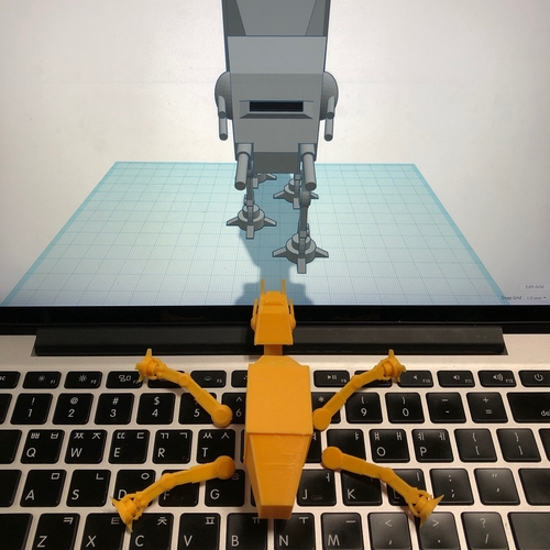 It is very similar to a skirt, but connected to the model. In addition to all the advantages of a skirt, the brim keeps the edges of the object being made on the table.
When printing, the outside of an object often cools faster than the middle, causing the edges to curl. Brim prevents this phenomenon by holding the edges.
Raft
A raft is a detachable base, made in the form of a thin mesh platform, located under the entire object (which lies on the raft). To create a raft, the printer first prints a flat plate in two or three layers, and then begins to manufacture the object.
The rafts provide excellent adhesion to the table surface and also provide a strong print base. This is especially useful when making small and oddly shaped parts that do not fit well on the table, as well as thin-walled objects.
After printing is completed, in most cases the raft will separate easily from the part.
If the printer does not have a heated desktop function
Rafts are used if the printer does not have desktop heating.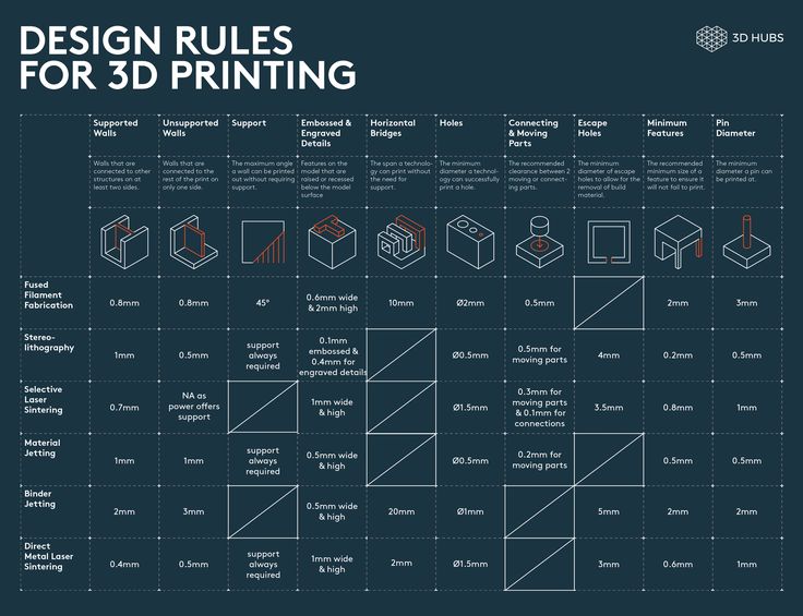 In this case, excessive adhesion becomes a problem.
An alternative method is to apply adhesive paper tape to the printer platform, with the edges down if possible (this protects the platform itself). You can also use packing tape, but it is usually more expensive.
If buckling does occur or the object separates from the table, apply a soluble glue stick to the adhesive tape. This will enhance adhesion.
Find out the features of a specific 3D printer and take them into account when preparing your model
3D printing is not only a science, but also an art. Effective design for subsequent 3D printing requires an understanding of the technological process, taking into account its features and the purpose of the future object. This will greatly improve print performance.
Using Solid Edge in 3D printing
Not all CAD systems are suitable for 3D printing
The capabilities of the applied system should not limit the designers. Our Solid Edge system is designed with the latest 3D printing technologies in mind. Various 3D printers and 3D printing services are supported.
Take it to the next level with specific techniques for designing 3D printed parts
Generative modeling in Solid Edge opens up new possibilities: the designer selects a specific material, sets the design space, allowable loads, restrictions and target mass of the part, and the system automatically calculates the desired geometry. As a result, 3D printing methods can produce the most complex shapes.
In addition, when building models, the use of the results of three-dimensional scanning is provided. Solid Edge successfully combines the traditional boundary representation of solid models (B-Rep) and the representation of surfaces in the form of a grid of triangles, which avoids time-consuming transformations that are fraught with errors.
If you've already downloaded an STL file for printing, our unique synchronous technology allows you to quickly and easily edit your imported models in Solid Edge in preparation for the process.