3D printing fine threads
3D Printing Threads and Adding Threaded Inserts to 3D Printed Parts (With Video)
There are many ways to attach screws to 3D printed parts, including inserts, tapping, and even 3D printed screw threads.
Screws are among the most popular fasteners in any material. Can you use off-the-shelf screws with your 3D printed parts? The answer is a clear yes, for both stereolithography (SLA) and selective laser sintering (SLS) parts.
In this article, we explore different methods of using metal screws with 3D printed parts, and provide some tips for incorporating screw threads directly into your 3D design.
Watch our application video about 3D printing threads and threaded inserts for 3D printed plastics.
Video Guide
Having trouble finding the best 3D printing technology for your needs? In this video guide, we compare FDM, SLA, and SLS technologies across popular buying considerations.
Watch the Videos
Let’s take a look at the various design options for 3D printed threads, which we’ve collected over the years within Formlabs and based on feedback from our customers. Our test part is designed to showcase all these methods at once:
We’ve grouped these options based on the type of fastening, with pros and cons of each option listed for different use cases.
Sample part
See and feel Formlabs quality firsthand. We’ll ship a free sample part printed on an SLA or SLS 3D printer to your office.
Request a Free Sample Part
In this section, we look at three ways to incorporate inserts and nuts into your completed 3D prints for strong, long-lasting fastening that stands up to multiple cycles of assembly and disassembly.
Pros
-
Very good hold into 3D printed parts
-
Metal threads are strong and wear-resistant
-
Installs with a simple press fit
Screw-to-expand inserts are cylindrical, with a slight taper and knurling on the exterior surfaces. During the design stage, incorporate a boss with a depth and diameter based on the insert’s specs into your part. Print and post-process the part as normal, following the usual steps for SLA or SLS post-processing, taking care to make sure no extra material remains inside the cavity, and install the insert with a simple press fit. Adding a screw will press the knurled surface into the surrounding printed material, creating a strong friction fit.
Tip for using screw-to-expand inserts with 3D printed parts made with SLA 3D printing: Wash the part as normal, insert the screw-to-expand insert, install a screw, and post-cure the part with the screw in place. Saving this step for last reduces the chance that the insert will crack the surrounding material when expanded.
Heat-set threaded inserts are designed to be installed into thermoplastics using a soldering iron with an installation tip. They can also be used as glue-in inserts in thermoset materials, such as SLA parts.
To install in a thermoplastic part, like one printed with SLS Powders, follow the installation instructions for your particular hardware. The typical process is to use a soldering iron, with or without a special attachment, to heat the insert, which conducts heat into the surrounding plastic. The surrounding material softens and, by pressing down with the soldering iron, you can gently press the insert into the printed part. Be sure to allow enough time for the material to cool down and regain strength before installing a screw.
To install in a thermoset part, like one printed with SLA Resins, glue can be used to hold a heat-set insert in place. Unlike with traditional installation, make sure to design your boss to match the widest diameter of the insert, and use a bead of cyanoacrylate (CA) glue or epoxy to hold it in place when installed. Be sure to allow enough time for your glue to fully cure before installing a screw.
Note: In the SLS 3D printed part photographed for this article, the boss is sized for a press-fit, as we recommend here for thermoset plastics. This also works, with a drop of glue or epoxy, for thermoplastic parts, but won’t have as strong a hold as a true heat-set installation.
Although an additional step of soldering or gluing is required, heat-set threaded inserts for both SLS and SLA parts offer improved security and strength compared to screw-to-expand inserts With either method, these are a great option to gain a little extra security and strength compared to screw-to-expand inserts, although the additional step and equipment may be inconvenient.
Cons
-
Pocket or boss needs to be designed into the part, and accessible after printing
-
Depending on geometry, may require glue and curing time
Designing a pocket or boss that securely holds a nut into the part itself is another method to get metal-on-metal contact. Hexagonal or square nuts can be used, and even locking nuts are possible to accommodate. There are many design variations for this method—just make sure your pocket or boss is easily accessible (i.e. not on an interior surface) so that the nut can be installed. For extra security, a drop of cyanoacrylate (CA) glue will hold the nut in place.
White Paper
Stereolithography (SLA) 3D printers such as the Formlabs Form 3+ have high accuracy and precision, and offer a wide range of engineering materials. Download our white paper for specific recommended design tolerances.
Download the White Paper
For speed and simplicity, it might be preferable to forego inserts and nuts in favor of screwing directly into a 3D printed part. Whether tapping threads or using a self-tapping screw, off-the-shelf hardware designed for use with plastics work well with 3D printed materials like resins and thermoplastic powders.
Using a thread tap designed for plastic is a quick, economical way to add screw threads to 3D printed parts. It doesn’t require any extra design steps, and most shops that work with plastics will already have the equipment required.
Self-tapping screws, also called thread-forming screws, can be inserted into a negative feature with no preparation work done to the part.![]() Follow the manufacturer’s guidelines for boss dimensions.
Follow the manufacturer’s guidelines for boss dimensions.
It’s suggested to use these with materials that are ductile, or have high elongation. Formlabs Nylon 11 Powder or Nylon 12 Powder are both suitable for this, as are the Tough and Durable Resins in the Formlabs SLA material family. Brittle materials, or those with low elongation (such as the Rigid Resins in the Formlabs SLA material family), may crack when used with self-tapping screws, so take caution and wear eye protection when using these materials.
Including threaded geometries in your printed part can be effective if you follow certain guidelines. Stick to larger thread sizes, at least ¼”–20 (imperial) or M6 (metric) or larger; reduce stress concentrations with fillets; and use thread profiles that are designed for plastics. For smaller screws, the threads should be customized to create a better fastener. For example, printing a semi-circular thread profile (on screw and nut) and using a 0.1 mm offset gives better thread engagement with improved wear characteristics.
SLA and SLS 3D printing are generally preferable for this method over FDM, because they are more precise and can create parts with a smoother surface finish. Any material with particularly low surface friction, such as Durable Resin, is less likely to show wear over multiple cycles of assembly and disassembly.
When preparing your part for printing, it's important to minimize support structures on any threaded surfaces to ensure your parts will come together smoothly without additional post-processing.
There are many options for combining multiple 3D printed components using screws and threaded fasteners. From directly 3D printing threads to using off the shelf inserts, you can choose any of the methods outlined above, based on the chosen material, the number of cycles of assembly and disassembly you anticipate, the strength required, and the amount of extra steps your workflow can accommodate.
Curious to see what 3D printing material might be right for your application? Use our interactive wizard to choose the best 3D printing material or request a free 3D printed sample part to see the quality firsthand.
Explore 3D Printing MaterialsRequest a Free Sample Part
A Beginner's Guide to 3D Printing Threads
Screws and threads are among the most popular fasteners in the world as they allow convenient joining in multiple complicated assemblies. For 3D-printed parts, threads are an important element that can allow the use of off-the-shelf screws and fasteners. However, 3d printing threads and incorporating them in the design can be a challenge without the right process.
This article brushes over the basics of 3d printed threads and discusses the best practices that deliver consistent results without any added complexities.
The Benefits of Using 3D Printing for Threads
Before moving on to the details of 3D-printed threads, it’s important to shed some light on why the industry prefers using them.
Allow Complex Design
Firstly, 3d printing threads allow the creation of even the most complex designs because there are only a few limitations to the technology. Similarly, other methods like machining and casting have several issues, internal materialistic flaws, and other quality issues while creating complex, integrated shapes.
3D printers, however, build parts directly in layers which allows better flexibility and performance. Moreover, 3D-printed screw threads don’t always have to be on the surface like other manufacturing methods. They can be hidden in the middle or other areas where it’s extremely difficult to add threads using other methods.
Have Smooth Finishing
Additional to the aforementioned advantages, another benefit of 3d printing threads is surface finishing. Furthermore, these surfaces are quite smooth and require little to no post-processing. Moreover, other processes like casting and machining require significant resources to prepare the part through grinding, turning, and other operations. However, the process becomes different in the case of additive manufacturing where there is no need for further post-processing once the part is completed.
Precision Printed Threads
Additionally, another benefit of using 3D printers is the precision, consistency, and high tolerance. Some applications demand all these because of their sensitivity and using 3D printing seems to be the only viable answer.
Cost-Effective Option
One more favorable thing about using 3D-printed screw threads and other parts is the cost-effectiveness for small-scale setups. Furthermore, using 3d printing for prototyping is one of the most important phases of any design project, and using traditional machining or other methods can consume a lot of time and resources. Using 3D printing instead can save both time and significant resources which facilitate multiple iterations and help optimize the designs to improve the overall performance of the project.
Design Terms for 3D Printing Threads
Before moving on to the incorporation of internal and external threads in a 3D printing design, it’s important to discuss some of the most common design terms anyone associated with the field should know about.
| Term | Description |
| External or internal threads | The only difference between these threads is their location. Internal threads remain within the surface and can’t be seen. External threads, however, remain on the surface. Bolts and nuts are the perfect example of that where threads on the bolt are external while nuts have internal threads. |
| Pitch | This refers to the distance between the two adjacent points on a screw. |
| Major diameter | The overall diameter of the screw starts from the furthest end of the screw to the center of the screw. |
| Minor diameter | The diameter of the screw without considering the dimensions of the thread. Moreover, it’s also called root diameter. |
| Thread axis | The imaginary line passes through the center of the cylinder in a screw. |
| Root | The inner groove of the screw runs around the threaded surface.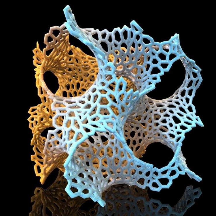 |
| Crest | The highest point of the screw that’s the furthest away from the center. |
| Head | The head refers to the topmost exposed area of the screw which is used to rotate the screw. |
| Form | The form is the overall shape of the thread ridge. The triangular or hexagonal profiles are some of the most common ones. |
| Taper | Some threads don’t remain in a straight line with adjacent crests parallel to one another. They instead have a tapered thread which helps in providing a tighter grip and seal. |
| Coarse & Fine Thread | This refers to how far the threads are. The finer the threads are, the greater the number of threads per unit distance. Similarly, coarse threads are the opposite of that and have a lower number of threads per distance. |
| Metric threads | Metric threads have a distance mapped in SI units. |
| Inch threads | The distance in these threads is in American units, which are in inches. |
Design Guide for 3D Printing Threads
Incorporating threaded design in any 3D printing design requires careful precision. However, as stated before, the process is more flexible and intuitive when compared with other traditional methods that the industry uses.
Software Package
The first question about threaded parts is about the software to use. Is there a special software package for threaded parts? The answer is no. Designers can incorporate threads or any other features in a 3D printing part with the same software package. For example, someone using Fusion 360 or SolidWorks won’t have to shift to any other program.
Moreover, the basics are more important. Anyone aware of the basic terminologies, their effect, and the overall requirement of the project would easily add the threads in the design file using very simple and easy-to-use functions. Irrespective of the software program, the basic function to create threaded parts remains the same. However, the steps differ slightly depending on whether the external or internal thread is needed.
External Threads
- Draw a circle of the diameter equal to the major diameter of the thread
- Use the extrude function to create a cylinder of the length required
- This step is a little bit different depending on the software. Find the option to create threads in the relevant tab. Add in all the details like the pitch and minor diameter and execute the function to create the thread.
Internal Threads
- Draw a hexagon of the same size as the threads
- Extrude the shape to the required length
- Create a hole in the center and set the diameter as the major diameter of the thread
- Select the internal surface of the hole and create the threads using the relevant option on the program
- Click the thread size and select all the other parameters before selecting ok
3D Printing Considerations and Settings
The process for 3d printing threads is quite straightforward. However, it isn’t always easy because of several considerations involved. The biggest limiting factor is the size as it’s considerably harder to add threads with a smaller diameter.
Moreover, the smallest size possible for a setup is dependent on the characteristics of the 3D printer. For larger diameters, any 3D printer can work because the thread has enough time to cool down while the nozzle is elsewhere. Similarly, for smaller diameters, it’s always better to test the 3D printer beforehand to avoid any issues down the line.
Apart from the printer characteristics, the calibration and settings are also important for reliable results. Here are a few general guidelines to ensure reliability and consistency in 3D printer performance when it comes to threads.
- Ensure that the printer and extruder are properly calibrated
- Set the level of the 3D printer bed
- Optimize the design to always ensure that the printer creates the threads vertically
- Make sure that the supports don’t go inside the threads.
 Otherwise, it will be difficult to remove
 - Use at least 4 vertical layers with 2mm walls to ensure stronger threads
- Select the infill density according to the application but don’t set it below 25% under any circumstances
Try RapidDirect Now!
All information and uploads are secure and confidential.
Common Ways to Add Threads to 3D Printed Parts
There are multiple ways of incorporating threads into a 3D-printed part. The best choice depends on the application and the requirements of the project. However, the following ways are the most common in the industry.
Printing Threads
Printing threads directly is among the most effective ways to incorporate threads in a design. It’s an ideal way because it allows custom design and delivers maximum flexibility to the users.
There are, however, a few limitations as well. Directly printing smaller diameters is quite difficult. Similarly, the threads don’t hold up for longer cycles of assembling and disassembling as the threads won’t be strong enough to add or remove a screw.
Furthermore, direct printing is not a viable solution for situations where a certain number of copies are needed. In such cases, manufacturers either need to have additional printers. However, that results in elevated costs.
Using Heat-Set Inserts
This is an excellent option as 3D printing is most common with thermoplastic and thermoset materials.
For thermoplastic parts, using heat set inserts is a viable option as it uses the combination of heat and pressure to permanently add the threads to an existing part. The process is extremely simple but time-consuming as it requires processing from a soldering iron and waiting for the part to cool down.
For thermoset parts, the process involves holding the insert with glue as well. Similar to the thermoset materials, this process also has a significant lead time as the glue requires time to cure before the installation of the screw.
Manually Drilling and Tapping
This is one of the quickest and most economical ways of adding threads to a 3D-printed design. The threads will provide an excellent hold, and the equipment needed to process them is simple and readily available in almost all workshops. The threads, however, won’t be too strong and they may also increase the overall lead time as the process itself is manual.
Combination of Multiple Elements
Finally, perhaps the most effective approach is to use a combination of methods. Add 3d printed threads in areas with limited accessibility and using the combination of aforementioned methods can deliver the best results. However, the lead time will be high as well because most of these methods require significant processing times.
RapidDirect: The Ideal Choice for 3D Printing Threads and Screws
Whether it’s 3Dprinting threads in a product or testing out a new design assembly for a specific application. Having the right manufacturing partner can make all the difference in performance. Therefore, RapidDirect takes pride in its long and successful history of providing the most comprehensive manufacturing services in the market. Our experienced 3D printing team has all the latest technology and the expertise of working with an extensive list of global clients to guarantee consistency and performance at the most competitive price.
One thing that sets RapidDirect apart is the intuitive online manufacturing platform. It has everything, anyone, thinking of starting a new project needs to gauge the existing prices and decide on the cost. To get started, simply upload your design files and configure your materials, finishing, quantities and more, and then get instant quotations, or request quotes with our sales engineers.
Troubleshooting 3D Printing・Cults
This article should help you identify various 3D printing related issues. Find the image or description in this list that best describes the problem you're experiencing. We offer some tips that should help you solve this problem.
As you know, 3D printing is an empirical process and it is through mistakes that you learn to understand, set up and use your machine. With the help of this list, you should be able to resolve the major bugs. If you are still experiencing issues or have additional tips to add to this list, feel free to contact us and let us know!
#1 Drooling
Symptom
Thin threads are woven into gaps between different parts of a 3D printed part.
Common Name: oozing
Possible Cause
Plastic continues to leak out of the head as it moves due to residual pressure in the heater and fluidity of the molten plastic.
Suggested remedies
Increase filament retraction length in Slic3r, retraction distance in CuraEngine. Retracting the filament will cause the pressure in the print head heater to drop. The effect can be modulated by adjusting the retraction speed directly in the slicer.
Increase print head speed. This allows the melted plastic to spread less time and leave marks between the printed parts.
Reduce the extrusion temperature of your plastic. If it is too high, the plastic becomes more fluid and flows out of the extruder faster.
#2 It is collapsing
Symptom
Collapse or poor quality of the overhanging surface, leaving small bumps.
Common name: overhang
Possible cause
The plastic deposited on the periphery of the protrusion does not solidify fast enough, so the deposited filament moves before it solidifies. The phenomenon is repeated or emphasized from one layer to another.
Suggested fixes
Vent the deposited plastic more efficiently, for example by adding a fan to the extruder or directly with a portable fan.
Create print supports under the overhangs.
Change part orientation to avoid overhangs.
#3 Flaking on the sides or top
Symptoms
Contours not bonded enough.
Flat surfaces are not completely covered.
Possible cause
Not enough material is deposited. Too narrow, the deposited wires do not touch each other enough and therefore do not stick to the adjacent wire.
There is dirt in the nozzle, which prevents the passage of the melt.
The extrusion temperature is too low, the wire dries out too quickly or shrinks and therefore does not stick to the adjacent wire.
Suggested Tools
Calibrate the extruder to obtain material flow according to data received from the slicer.
Unlock the extrusion nozzle.
Increase extrusion temperature.
Increase the blending speed in your slicer.
#4 There is not enough material on thin parts
Symptom
The edges of a very thin area are not strong enough, there is not enough material.
Possible cause
Recycling or reworking is not effective enough.
Incorrect filament solidification.
Thread drive slippage during retraction.
Suggested remedies
Reduce the retraction speed and length while printing.
Increase "extra leg length when retracting" when using Slic3r.
Increase the spring pressure on the driven gear.
#5 Blisters
Symptom
Blisters, mismatched geometry, such as small bumps that are seen mostly in areas with a small surface area.
Possible cause
The filament is too hot during extrusion or the filament cooling system is not effective enough.
Suggested media
Place more parts on the plate while printing. In this case, the nozzle will print more objects and therefore allow more time for the part to cool before passing over it again.
Improve the cooling of your 3D printed object by adding cooling systems.
#6 Thin walls delaminate
Symptom
At a thin wall without filler, the threads diverge, they are not glued together on the sides.
Possible Cause
The walls of your 3D print are too thin or not adapted to such a small size.
Suggested remedies
Draw thicker walls to adapt to the thread thickness.
In the slicer settings, set a sludge width that is a sub-multiple of the wall width while remaining consistent with the extrusion diameter and layer height.
Change slicer.
#7 Layer shifts horizontally
Symptom
The layer is shifted in the X or Y axis (or both).
Possible Cause
Print head or plate movement problem.
Suggested fix
Reduce the acceleration on the axis that has the problem.
#8 Layers shift evenly
Symptom
Layers almost always shift along the X and/or Y axis after a certain print height.
Possible Cause
Head or plate offset failure due to overheating of motors going into safe mode.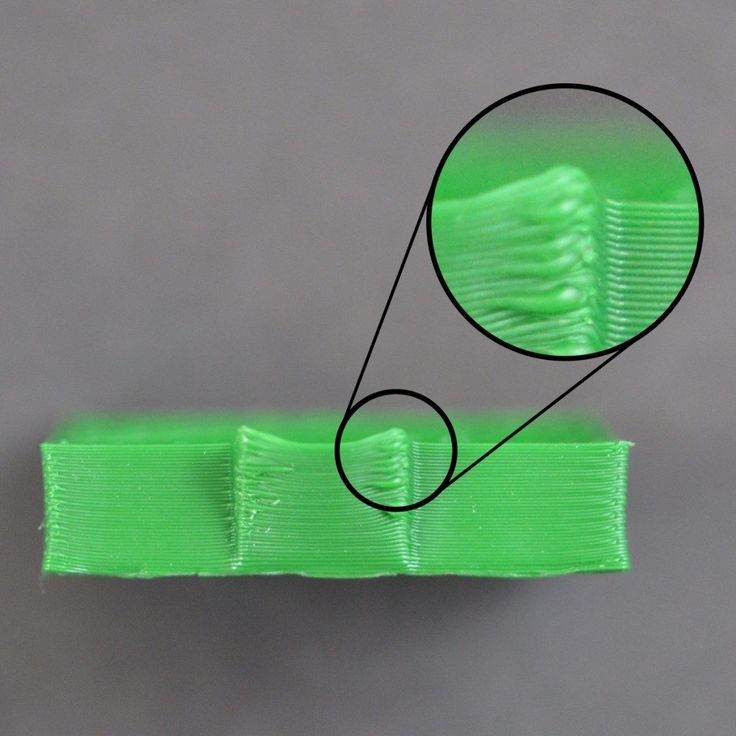
Suggested fix
Cool engines with cooling systems (fans).
#9 Corners curl up
Symptom
Deformation in the Z direction during 3D printing. This figure increases in case of a strong overhang.
Common name: curling
Possible cause
Poor solidification, shrinkage effect due to temperature difference of the wire deposited on the previous cooled layer.
Suggested remedies
Increase the slope in the 3D part to reduce overhang.
Further cooling of the deposited plastic using a ventilation system.
Add print supports to affected areas.
#10 Corners fall off
Symptom
The corners of the printed object are peeling off the plate, creating an uneven base.
Common name: warping
Possible cause
Poor fit between the workpiece and the insert.
Material shrinkage factor too high.
The first layer is not pressed enough against the board.
Suggested remedies
Change media as PLA is less likely to warp.
Apply adhesive to the printing plate (glue, tape, varnish, etc.).
Correctly adjust the plate height before printing.
Apply a thinner first coat to further crush the deposited wire.
Add a bezel under the first layer.
Heat up the stove.
Clean and degrease the base.
Change the filling strategy. Fill the bottom concentrically instead of linearly, then fill the inside in a honeycomb pattern to avoid any shrinkage effect.
Reduce the internal fill density of your 3D printed object.
#11 Extrusion density too low
Symptom
Incorrect material density.
Possible cause
Material consumption too low
Suggested remedies
Unlock the extrusion nozzle.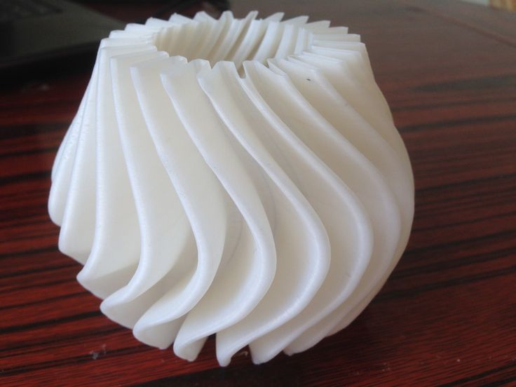
Filament blocked upstream of extruder (e.g. knot in spool)
Check thread drive (e.g. knurled screw problem)
Corners #12 not forming correctly
Symptom
The corners are not straight enough, they can even stick out and increase the size of the part.
Possible cause
Too much material is deposited in the corner due to the nozzle slowing down too much as it passes through the corner.
Suggested remedies
Intentionally soften the corner of the part in the 3D modeling software.
Increase the "jerk" on your 3D printer's axis controller.
#13 There are black drops
Symptom
Burnt (blackened) plastic in some areas of the printed object.
Possible Cause
Poor nozzle seal causing burnt PLA or ABS to drip around the nozzle.
Suggested fix
Remove the nozzle and close it again.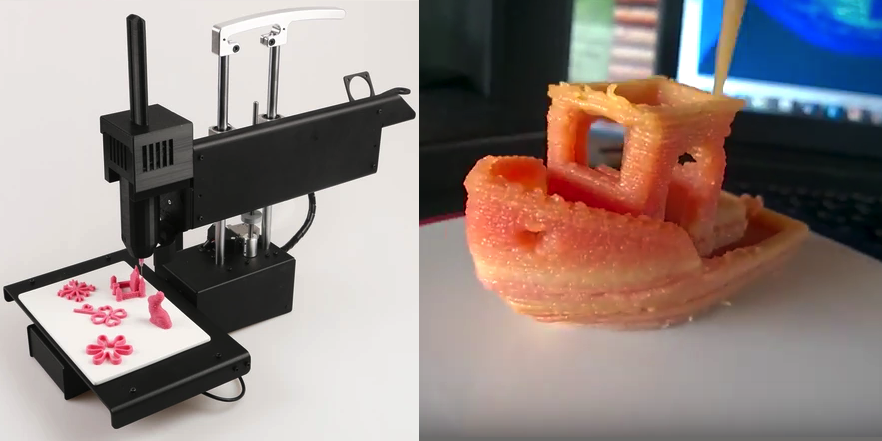
#14 Layers poorly welded
Symptom
Part breaks at the attachment point between two printed layers.
Possible cause
Too much cooling, the deposited layer does not adhere well to the previous layer, because it was not hot enough during the deposition.
Suggested remedies
Reduce fan speed during printing.
Increase the minimum print speed in the slicer.
#15 Bubbles form on the first layer
Symptom
The first layer comes off the plate locally in the form of bubbles.
Possible Causes
Moisture in the material which gradually evaporates on contact with the heating plate.
Insufficient heating plate temperature for the material being used.
Suggested products
Store raw material rolls in a dry place, in closed packaging, with a desiccant bag.
Dry damaged material: place in a rotary oven at 40°C for approximately 3 hours. Be careful not to heat above 45°C or 50°C as this may cause the threads to stick together in the bobbin and even lose their cylindrical shape.
Increase the temperature of the heating plate.
Printing on tape or special adhesive.
#16 Fragile top and bottom
Symptom
Horizontal sides too thin and brittle.
Possible Causes
Insufficient material thickness above and below thin fill print. The laid threads have too few support points and break between the threading ribs.
Suggested remedies
Place at least 2 or 3 fully filled layers ("Solid layers" option in Slic3r) for the "top" and "bottom" faces.
Increase the fill of your object.
#17 Hole tops collapse
Symptom
Horizontal center hole top wires collapse during construction.
Possible causes
Plumb line too horizontal.
Mismatch between nozzle temperature, wire cooling and speed.
Suggested fixes
Reduce or eliminate this overhang area by modifying the 3D file geometry. An example is in the large hole in the photo, shaped like a drop of water, not a cylinder.
Add print supports below this area if the overhang is too difficult for the 3D printer.
Avoid too much slowdown in this area, even if the layer print time is short.
#18 Color or transparency varies
Symptom
The color or transparency of the material changes in different areas during 3D printing.
Possible causes
Different crystallization of the material due to different cooling rates. This may be due, for example, to the printing time of individual parts of the object or to the power of the fan.
Radiation from the nozzle can affect the thermal cycle of the previous layer and thereby change its appearance.
The applied layer is too hot because the underlying layer has not cooled down.
Be careful, the physical-mechanical properties of the part may change due to these differences in crystallization!
Suggested fixes
Better control of cooling with slicer settings: change fan power based on plate cooling time or slow print speed in proportion to plate surface.
Reduce extrusion temperature for faster and more uniform phase transition.
#19 Layers are delaminating
Symptom
Some layers are bent and cracks appear between the different printed layers.
Possible causes
Twisting phenomenon due to the effect mentioned in #9 the above happens between layers.
The wire cools too quickly at the exit of the nozzle, it does not weld properly with the previous layer.
Severe contraction of the material during cooling or phase change.
Some materials extruded at high temperature (ABS, PC...) may present a significant shrinkage phenomenon.
Suggested remedies
Change the extrusion temperature.
Change the media.
Avoid blowing on a wire that has been set aside, reducing fan power, or placing the printer in a draughty room.
Close the assembly area in a controlled cabinet at a temperature close to the glass transition temperature of the material.
#20 Drops appear
Symptom
Drops of material are deposited at various points on the side of the 3D printed object.
Possible Causes
Excessive extrusion when resuming extrusion after stopping extrusion when moving from one point of the part to another or when changing layers.
Suggested Remedies
Some slicers have a setting that after a pause in printing, request that more be pushed in before resuming normal printing than was removed by retraction.
#21 Bowden extruder salivation
Symptom
The Bowden extruder is either running too hard or not running enough. First impressions of your extruder are not great, too much extruded material, bridges between different areas in motion where extrusion should stop.
Possible cause
Insufficient thread shrinkage to compensate for the gap in the Bowden tube. Depending on the diameter of the tube and filament, as well as the length of the body, the motor must draw a certain length of filament through the bends of the tube before the filament is drawn out of the heating head.
Suggested fixes
Increase the "pull" distance in the slicer. The detail on the left was printed with 1.5 mm of indentation, which was clearly not enough. When the pull-in distance was increased to 6mm, the center part was printed. Too much shrinkage causes hot material to enter the thermal break, the temperature of the thermal break gradually rises, and the melting thread eventually gets stuck in the thermal break. The engine is no longer able to effectively push it. Reducing the retraction distance to 4 mm results in the part shown on the right.
#22 Streaks or regular patterns on extrusion
Symptom
Repeating patterns appear on the walls of 3D prints.
The pattern may change depending on the direction of movement of the motors.
Possible cause
Incorrect extruder drive setting
This problem can occur if the extruder is set to the wrong current. If the extruder has insufficient power, the extrusion will not be constant.
Suggested remedies
Adjust the extruder driver with a multimeter. Be careful not to short circuit during the measurement, use a ceramic screwdriver.
Artwork by Philippe, Pierrot and Franck and originally posted on LOGre
This page has been translated using machine translation. Suggest the best translation
Problems, defects, 3D printing errors and solutions
Often during the operation of a 3D printer, problems may arise due to which defects appear on the finished model.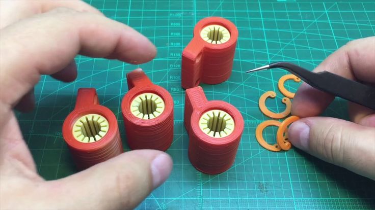 Or instead of a neat product, plastic noodles suddenly appear on the table.
In fact, the causes of defects can be conditionally divided into 2 types - these are physical and software.
Physical ones are those that arise due to problems with the mechanics or any other causes that can be eliminated physically. These include problems with printer mechanisms (belt tension, backlash), clogged or deformed nozzle, incorrect table geometry, etc.
Software - these are defects that occur due to incorrect slicer settings or, less often, errors in the printer firmware. For example, incorrectly selected print speed, retract settings, incorrectly selected temperature for plastic, etc.
Very rarely, the problem may lie in the wrong or “flying” printer firmware (although usually the printer simply will not start then), overheating of some boards during printing, etc. These are rather special cases, so we will not consider them.
Model peels off or does not stick to platen
This is the most common 3D printing problem.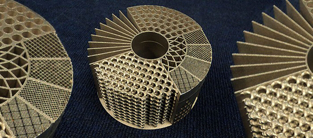 Every 3D printer has had a case when the first layer treacherously rolls, clinging to the extruder, or the most offensive - when it tears off a partially printed model from the table. The first layer must stick tightly otherwise nothing will be printed.
Gap between table and nozzle 9 too large0547
This is the most common reason. You just need to set the correct gap between the table and the nozzle.
Modern printers often use an auto-calibration (auto-leveling) table system or an auxiliary table leveling program. To calibrate such printers, use the instructions. If there is no manual, it can be downloaded from the manufacturer's website.
If you have a simple printer without auto-calibration, a self-assembly or KIT kit, use a probe or a piece of paper folded in half to calibrate. The probe should be slightly pressed against the table by the nozzle. Before calibration, the table and extruder must be heated. Align the table surface over each adjustment screw (there may be 3 or 4) in turn, and only then check the center point.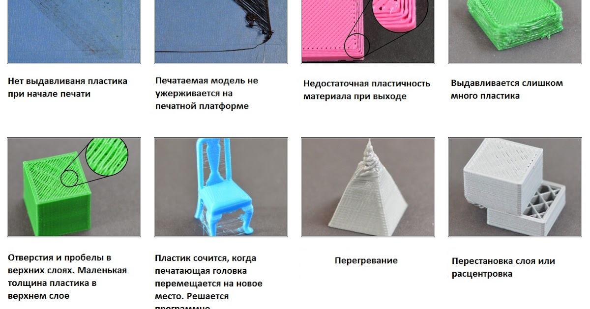
If you're having trouble getting your table surface perfectly level, try raft printing. Raft is a thick substrate in several layers that is printed under the model. It will help smooth out the slight curvature of the table.
A small cheat sheet to determine the correct gap for the first layer
Plastic with poor adhesion
Some types of plastic, due to various reasons, such as large shrinkage, do not adhere well to the surface of the printing platform. In this case, try using stickers or special 3D adhesives to improve adhesion between the table and the first layer of plastic.
In the early days of 3D printing, there were experiments with different homemade 3D adhesive recipes. ABS diluted in acetone, BF glue, sugar syrup and even beer. Some experiments have been successful. Until now, some enthusiasts use some types of hairspray or glue sticks as 3D glue. But still they are inferior in their properties to industrial 3D adhesives.
Some types of high temperature plastics with a high percentage of shrinkage (ABS, Nylon, etc.) may peel off the table during printing. This is due to uneven cooling and “compression” of the model (the lower layers have already cooled down, but the upper ones have not yet). For such plastics, it is imperative to use a 3D printer with a heated table and a closed case.
Plastic temperature too low
The hotter the plastic is when it exits the nozzle, the better it will adhere to the print bed. It is better to print the first 5-10 layers at a higher temperature (+ 5-10 degrees) and turn off the blower fan.
Wrong first layer settings (speed and thickness)
A thicker layer sticks easier, so the standard first layer is 0.3mm thick. With an increase in print speed, the heating block may simply not have time to heat the plastic to the desired temperature and it will stick to the table worse. Before printing, check the speed and thickness settings of the first layer in the slicer.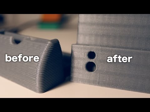
A lot depends on how the 3D printer prints the first layer. Try to control the printing of the first layer and only then leave the printer to work alone.
Plastic does not choke from nozzle
The printer has already begun to print, but the print table remains empty. Or part of the model did not print.
Clogged nozzle
In 3D printing, a nozzle is a consumable. The nozzles are clogged or worn out (frequency depends on the type of plastic). The simplest thing is to replace the nozzle. But if there was no spare at hand, you can try to clean the old one. To do this, there is a whole set of thin needles. Or you can heat a clogged nozzle above the melting point of the plastic and “burn out” the blockage. But later it is still better to replace the nozzle.
Low temperature nozzle
You need to increase the temperature of the extruder in the slicer settings or check the thermistor and heating block. Sometimes the thermistor may not read the temperature correctly due to a malfunction or incorrect 3D printer firmware settings.
If the problem occurs after replacing the thermistor - contact the manufacturer or read articles about PID tuning.
Empty extruder
As the extruder heats up, plastic begins to ooze out of the nozzle. Because of this, the extruder may start printing half empty. Because of this, part of the first layer is not printed. You can push the plastic manually by simply pushing the bar into the nozzle. Or solve this problem programmatically - in the slicer, add a contour print around the model (one line).
Some manufacturers and 3D enthusiasts add a line print on the edge of the table at the beginning of each GCode. This is done so that there is plastic in the nozzle by the time the model is printed.
Feed mechanism does not push through plastic
The plastic pushes the feed mechanism to the extruder - a motor with a special pulley put on the shaft. If for some reason the plastic is not pushed through (nozzle clogged, extruder temperature low, etc.), then the pulley “gnaws” through the bar. You need to push the plastic bar with your hands or cut off the damaged piece.
Elephant foot
The first layers of the model are wider and protrude beyond the boundaries of the model. This is due to the fact that the upper layers put pressure on the first ones that have not yet cooled down and flatten them.
Table high temperature
Due to the too high temperature of the table, the lower layers remain soft for a long time. Try lowering the table temperature. It is better to reduce gradually (in increments of 5 degrees). You can try to turn on the blower when printing the first layers.
Small gap between nozzle and platen
If, when printing the first layer, the nozzle is too close to the table, then excess plastic will be forced out. After a few coats, this will not be as noticeable, but can lead to the effect of an “elephant's foot”.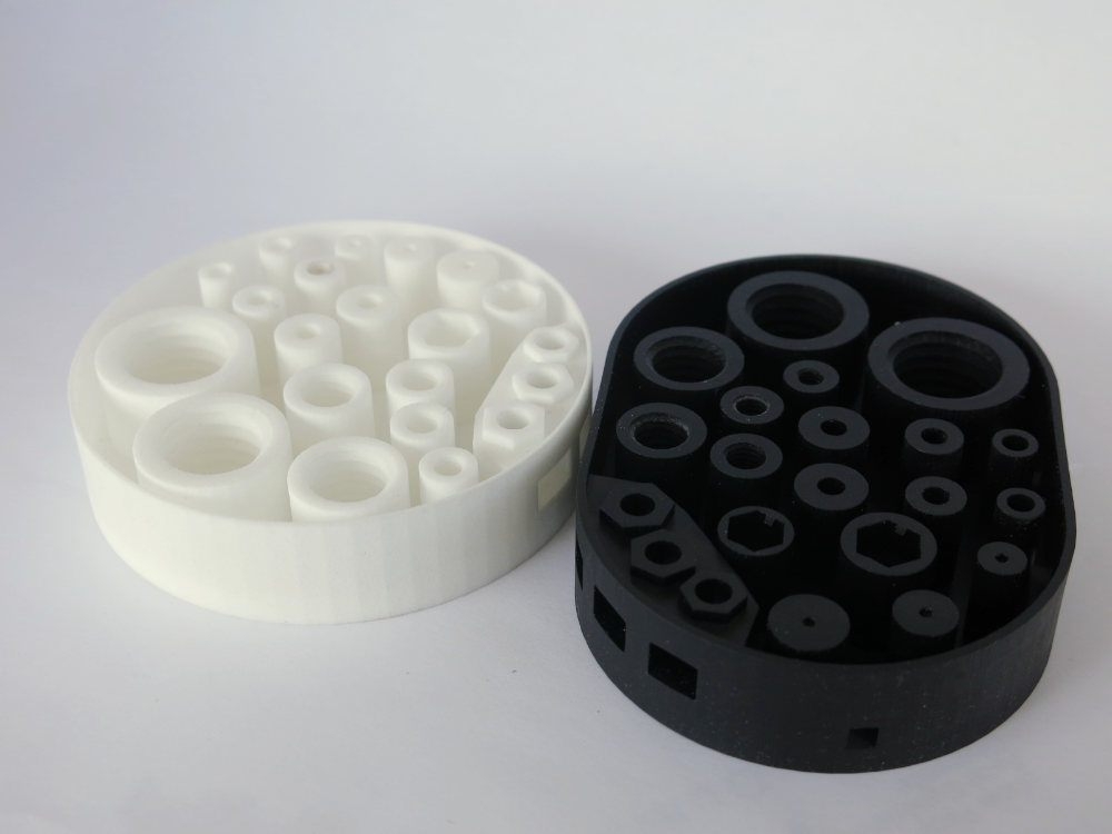
Plastic re-extrusion
When too much material is squeezed out of the nozzle, the walls of the model are not smooth, but bumpy, with sagging.
The solution is software - in the settings of the slicer, you need to set the material feed rate (fluidity) to a lower value. The average value is 95-98%.
It is worth checking the diameter of the rod. If its size is greater than 1.75, then the plastic will be squeezed out more than necessary.
Plastic underextrusion
The plastic is squeezed out too little, because of this, gaps may appear between the layer. The finished model will be fragile and fragile.
Wrong thread diameter
Check the filament diameter in the slicer settings. Sometimes, instead of the popular 1.75, the default is 2.85.
Incorrect feed rate settings
Check the fluidity settings in the slicer. The average should be 95-98%.
Clogged nozzle
Something could get into the nozzle and partially block the exit of the plastic. Visually, the plastic will choke from the nozzle, but in a smaller amount than necessary for printing.
Hairiness or cobwebs on finished model
Thin threads of plastic protrude from the outer wall of the model (most often on one side). The defect appears due to the flow of plastic from the nozzle during idle movement.
Insufficient retract
A retract is a slight pull of a plastic filament from an extruder. Due to the retract when the extruder is idle (from layer to layer or from model to model), heated plastic does not drip from the nozzle. For some flowable plastics (eg PETG) the speed and amount of retraction must be increased.
"Hairiness" can be easily removed by grinding or cutting off the threads with a sharp scalpel.
High temperature extruder
The higher the extruder temperature, the more liquid the plastic becomes. It is important to find a balance so that the plastic is not too liquid and sticks well in layers.
In the selection of the optimal extruder temperature, a test model - a tower - helps a lot. It clearly shows how plastic behaves when printed at different temperatures.
.
Temperature test
Top "perforated" or uneven
The top of the model is bumpy or with holes. The problem may arise if the top of the model is flat. For example, like a cube.
Insufficient airflow
When printing the top plane (cover), the plastic does not have time to cool down and remains too liquid. Because of this, the threads are torn and holes are formed. Increase the fan speed on the last layers.
Few top layers
The top of the print may be too thin and deform as a result. Check slicer settings. The number of upper layers is not recommended to be set less than 6.
Low percentage of filling
If the infill percentage is too low, then the top layer will simply have nothing to rely on. Increase the fill percentage in the slicer settings.
Model deformation
Some parts of the model seem to have melted in some places or on one side. The problem most often occurs when printing with PLA plastic. The defect appears due to the fact that the plastic does not have time to cool and deforms.
Insufficient airflow model
Turn the fans on to maximum. If their power is not enough (in some printers, the fan is located only on one side), you can put a regular desktop fan and direct it to the 3D printer table.
Small model
Small models are difficult to blow well. Try to print small items alongside larger ones, or place several identical models in different corners of the table. So the plastic will have more time to cool.
Layer offset
Layers shift along the x or y axis during printing.
Print head jam
Turn off the printer and try to move the extruder along the x and y axes with your hands. The extruder must move freely. If there are jams, check the mechanics of the printer. Bearing wear or the curvature of the shafts may be to blame.
Electronics overheating
Sometimes electronics problems can be to blame for misaligned layers. The most common cause is overheating of the drivers or too low current exposed to them.
Table top is loose
This is most often seen in 3D printers with glass. During printing, the nozzle may hit the model and move the glass slightly. Before printing, check if the glass or other printing surface is well fixed on the heating table.
Skip layers
Small holes are visible on the print, or the shell of the model is not continuous.
Teflon tube deformed
There are 2 types of thermal barriers - all-metal and with a Teflon tube. If overheated, the Teflon tube may deform. Plastic will pass through it, but in a smaller amount.
Low extruder temperature or high print speed
If the extruder is not heated enough, then the plastic will not be liquid enough and simply will not have time to be forced through the nozzle. The higher the print speed, the higher the extruder temperature should be.
Sometimes the outer walls print well, but the infill is “torn”. In this case, slow down the infill print speed in the slicer.
Model bundle
Cracks form on the surface of the printout during or after printing. Cracks can be large or very small. Most often, this problem occurs with plastics with a high percentage of shrinkage - ABS or Nylon.
Sudden temperature difference (if model delaminates during printing)
With a sharp temperature difference (for example, a draft), part of the model cools down faster. This leads to uneven shrinkage and incorrect distribution of internal stress. For plastics with low shrinkage, this is not critical. But if the shrinkage percentage is more than a few percent, the model may burst in layers.
For printing with such plastics, it is recommended to use a printer with a closed housing. If this is not possible, try to avoid drafts and sudden temperature changes in the room where the 3D printer prints as much as possible.
Print temperature
Due to too low printing temperatures, the layers may not “stick” well to each other. Raise the print temperature in the slicer settings.
Hardening (if the model cracks after printing)
Sometimes cracks appear on the model a few days after printing. This is due to uneven distribution of internal stress after cooling. You can try to “harden” the finished product.
For hardening, the model is placed, for example, in an oven, and heated to the softening temperature of the plastic. After that, the heating is turned off and the oven is left to cool slowly with the model inside. Due to this, the stress inside the print is distributed more evenly. But accuracy is very important in this method - if you make a little mistake with the temperature, the finished product can “float”.
Ringing
In places where the extruder changed direction, ripples are visible. Most often it looks like a shadow around the “sharp” protruding elements of the model.
Mechanical problems
Sometimes the problem occurs due to extruder play. Check if the extruder mount to the rails is loose. Be sure to check the tension of all belts.
High print speed or high accelerations
Moving the extruder too fast can cause vibrations that cause ripples on the wall of the model. The lighter the weight of the extruder, the less noticeable the ripples will be. To get rid of ringing, simply reduce the print speed in the slicer settings.
Slits for thin-walled models (not solid shell)
The thin wall of the model is not solid, but consists of two thin walls with a narrow gap between them. This problem is often faced by fans of printing "cutting" for baking.
Left model with wall defect, right without
Wall thickness and nozzle diameter mismatch
If the wall thickness is 1 mm, and the nozzle diameter is 0.4, it turns out that for a solid wall, 2 nozzle passes are few, and 3 are already many. The result will depend on the slicer algorithm, but most often you will get 2 walls with a thin slot in the middle (the slicer cannot change the wall thickness). The solution to the problem may be a slight refinement of the 3D model or the use of a different slicer.
Algorithms for calculating 3D models are constantly being improved and refined, and now this problem is less common.
When modeling, take into account not only the thickness of the nozzle, but also the percentage of “overlapping” of lines on each other. If you have a nozzle with a diameter of 0.4 - make the wall in your model not 0.
8, but 0.7 - 0.75.
Wrong model geometry
When instead of a circle you get an oval, and instead of a square you get a semblance of a rhombus.
The main reason is malfunctions in the mechanics of the printer. Be sure to check:
Belts
Check belt tension in x and y. Belts stretch over time and may need to be tightened or replaced. Each 3D printer has its own way of tightening the belt. If the belts are slightly stretched, you can tighten them with the help of a "spring".
Loose pulleys, etc.
Check if all bolts and nuts are tight. Are there backlashes. Pay special attention to tightening the pulleys located on the motors along the x and y axes.
Sagging of some parts of the model
Some parts are not printed, broken, or instead of a neat surface, a swollen plastic snot is obtained.
No support for overhangs
A 3D printer cannot print in the air, so if there are overhanging elements in the model, you need to set supports - supports. The slicer can set the necessary support itself, you need to check the appropriate box in the settings.
When printing with soluble support, you can set the gap between the model and support - 0. This will make the surface smoother. If the support material and the model are the same, you need to add a small gap. Otherwise, it will be difficult to separate the support from the model.
Split model
Sometimes the supports can take more plastic than the model. In this case, to save material and time, it will be more convenient to cut the model. If you have more than one 3D printer, then the model will print several times faster.
When cutting the model, you can leave grooves or mortgages so that the pieces of the model are connected without displacement.
Totals
In this article, we talked about the most popular 3D printing defects and how to solve them. Don't be intimidated by such a long list.