3D laser scanner zeiss
ZEISS colin3D - Optical 3D capture and 3D analysis
- Download information
Overview
Brochures & Technical Data
Success Stories
Recommendations
Contact us
Highlights
- Perfectly matched to optical 3D sensor systems from ZEISS Optotechnik
- Fast triangular network generation
- Surface comparison with report function
- Intuitive network processing
- Documentation of calibration
- Monitoring of system accuracy
- Automatically high-quality measured data through intelligent quality criteria
Innovative functionality
The ZEISS colin3D software platform is designed to ideally complement the COMET, COMET Photogrammetry and T-SCAN sensor systems. The program independently identifies the ideal strategies for merging individual images (matching) and guides you to the ideal result using a completely redesigned, project-oriented user interface. Thanks to the CAD integration, you receive continual feedback about the component surface areas that still need to be captured.
Maximum performance
Based on years of programming experience with 64-bit operating systems and the corresponding hardware such as graphics cards and multi-processor systems, the new algorithms of ZEISS colin3D achieve maximum performance and data quality.
Optimal user support
To quickly and efficiently position the T-SCAN system from ZEISS, the measurement field and scanner can be optionally displayed in ZEISS colin3D, making it easier to determine the ideal tracker position. Measuring programs for applications using the rotary tables COMETrotary and COMETdual rotary can be easily generated and executed. All individual measurements in a measurement sequence are subjected to quality checks and automatically repeated if necessary.
Quick triangular network computation using high-quality data reduction
Simple off-color comparison
Data analysis functions
For quality assurance applications, the scan data can be compared on the surface of a CAD model using a simple best fit alignment. ZEISS colin3D contains a simple false color display with a color gradient and fixed values. To more precisely analyze deviations, users can place the flyers on the surface individually as required. Reports for documenting the measurement results can be easily and quickly generated and managed.
Download more information
See how other customers use this product:
3D data opens door to New Knowledge
University of Würzburg uses a ZEISS COMET to document and evaluate archeological finds at excavation sites.
A precise grip and perfect trajectories
August Mössner GmbH & Co. KG optimizes production and programming with ZEISS T-SCAN
Digitizing Cast Parts with Laser Scanners
VULKAN Measures Coupling Components Optically
For perfect Gap and Joints
BMW in Munich increases process reliability for front and rear end assembly with ZEISS T-SCAN
Improving Speed, Quality and Employee Retention
Landolt inspects delivered parts prior to assembly with ZEISS T-SCAN and performs reverse engineering jobs.
Precision for Guaranteed Stability
PERI checks key components for formwork and scaffolding systems with ZEISS COMET and ZEISS T-SCAN.
The Foundation for Innovation? Perfect 3D Models
JP3D TecVision specializes in additive manufacturing methods and uses the ZEISS COMET in its production processes
The superlative in measuring technology
Swiss manufacturer of water fittings increases quality with ZEISS T-SCANCompatible CMM:
ZEISS COMET 6
High-end 3D sensor for high-precision 3D digitization
Available software:
ZEISS REVERSE ENGINEERING
Reverse engineering, tool correction and volume calculation
Available services:
ZEISS Academy Metrology
Qualification tools and services, customized to your needs and ready to elevate your skills and expertise.
ZEISS Metrology Portal
Your digital access point to all metrology services
ZEISS T-SCAN hawk | Portable Handheld 3D Scanner
Prev Next
Attending IMTS 2022? Here's What To Expect
Your Guide to High Precision Metrology Services
Is a High-Resolution 3D Scanner Worth the Investment?
The Checklist Every Professional Needs for Choosing a 3D Scanner for 3D Printing
What You Need to Know Before Implementing Automated Inspection
ZEISS T-SCAN hawk
All The Power of Advanced 3D Scanning— in Your Hands
Book a Demo Today!
The ZEISS T-SCAN hawk is a lightweight handheld 3D scanner built for heavyweight work. Powered by pre-installed GOM Inspect software, it takes you from data acquisition to data analysis, quickly delivering high-quality 3D data for high-quality results.
Professional Metrology-Grade Handheld 3D Scanner at Your Fingertips
| The Speed and Versatility You Need to Get the Job Done With a quick setup and no additional equipment needed, the T-SCAN hawk lets you get to work right away. Switching between each scanning mode enables you to collect complete full-field measurements using this single solution that feeds data directly into GOM Inspect for a faster workflow. |
Portable 3D Scanning You Can Take with You Anywhere
Compact and lightweight, the T-SCAN hawk 3D scanner is easy to travel with wherever you need to capture accurate 3D measurement data. Whether you need it on the shop floor or in production, take it with you wherever you go to quickly perform reverse engineering, quality control and more. Whether you need it on the shop floor or in production, take it with you wherever you go to quickly perform reverse engineering, quality control and more. |
Accurate 3D Measurement Data You Can Rely On The T-SCAN hawk handheld 3D scanner is a complete solution. With multiple laser sources and three scanning modes, this accurate hand scanner can accomplish photogrammetry of large objects, collect data from fine details or deep pockets with maximum precision to simplify your entire workflow from scanning to evaluation and reporting. |
Import 3D data into the leading metrology software regardless of the measuring system. As an all-in-one, easy-to-use, intuitive software solution, GOM Inspect supports your entire workflow from 3D printing and reverse engineering to inspection, evaluation, and reporting. Designed to make your workflow simpler and faster, it's no wonder hundreds of thousands of professionals rely on GOM Inspect, making it the standard in 3D inspection.
Book a Demo Today
Handle very large or heavy object scanning with this simple solution. With the T-SCAN hawk's built-in photogrammetry, you'll gain highly reliable real-time results delivered by a single handheld device. Easily scan various objects with enhanced precision— because no challenge is too big for the T-SCAN hawk.
The T-SCAN hawk is a fast and reliable solution for collecting the precise data you need to support reverse engineering. Quickly go from shape to CAD model, save and archive data from tooling and legacy parts, including the smallest details and intricacies, so you don't miss a thing.
Maintenance
The portable T-SCAN hawk is a valuable tool for 3D inspections of wear and tear. Bring it with you indoors or outdoors for maintenance, repair and overhaul and quickly accomplish trend analysis for multiple evaluations.
Quality Control
The T-SCAN hawk captures high-resolution data, delivering quality you can see clearly.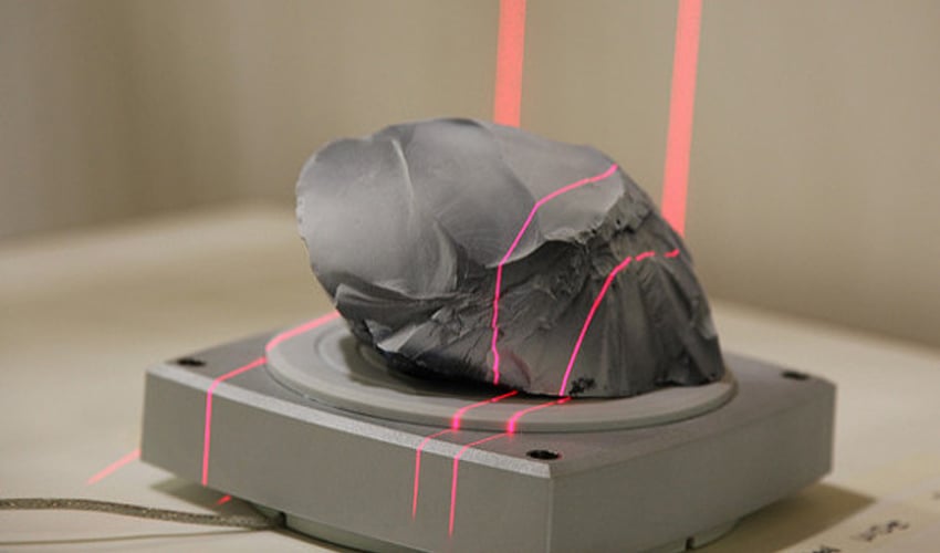 With the accurate data you need to make decisions with confidence, you'll quickly complete first article inspections (FAI), supplier quality inspections, shop floor inspections, functional dimensioning, part to CAD inspection, and beyond.
Change scanning modes within the same scan job for maximum versatility
| Red Crosses Collect complete data from large sections with 14 crossed red laser lines that provide a scanning area of 550 mm x 600 mm. Finish fast 3D reconstruction or use this mode for general scanning sessions. | Single Red Line Conquer confined areas with precision using a 0.01 mm single red laser line. Scan deep pockets or hard-to-reach areas when you switch to this scanning mode. |
Blue Lines
Capture fine details and collect accurate data from small parts. With four parallel blue lines and a scanning resolution of 0.05 mm, you'll also be able to tackle dark, shiny, or reflective surfaces in this mode. With four parallel blue lines and a scanning resolution of 0.05 mm, you'll also be able to tackle dark, shiny, or reflective surfaces in this mode. |
Book a Demo Today
back to top
© Copyright 2022. Capture 3D, Inc. All Rights Reserved.
Digitization of cast parts with ZEISS laser scanner
Andreas Ladwig, Associate Lean Specialist, and Ralf Redekker, his colleague from the Vulcanization Department, are studying the coupling segment.
Problem: Measuring a large range of couplings
VULKAN's RATO S range of couplings consist of several cast parts. To achieve the required elasticity, two of these molded parts are joined by vulcanization. Problem: The parts provided in the technical drawings and the parts actually received did not always match
at 100%.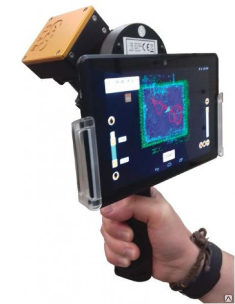 This meant that employees needed additional time to finalize them. In order to improve the manufacturing process, it was necessary first of all to provide an accurate analysis of the cast parts. "The range includes over 40 variants and sizes," says Andreas Ladwig, Associate Lean Specialist. "It would take us years to collect data on their geometric shape with calipers." A faster and more accurate method was needed.
Optical path indication simplifies scanning.
Solution: ZEISS T-SCAN CS handheld laser scanner
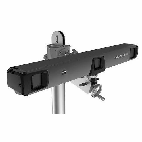
VULKAN introduced the ZEISS T-SCAN CS laser scanner into the inspection process. It digitizes the product relief by scanning 210,000 individual dots in one second. From these point clouds, data acquisition software from ZEISS generates a 3D model of the product. The operator first clamps the cast parts in a fixture directly at the production site. During the scanning process, the ZEISS T-TRACK CS+ tracking system camera, mounted on a nearby rack, registers the points captured by the laser scanner in a virtually fixed coordinate system.
Fast measurement with ZEISS handheld laser scanner
Ralph Redekker, from the Vulcanization Department, digitizes a sleeve segment using T-Scan. The first signs of successful process optimization are already visible.
Benefit: Fast digitization, less scrap
Ladwig and colleagues compared CAD models with scanned images produced with ZEISS INSPECTplus software. Then
they updated the "old" CAD models and sent them to the casting supplier. The "new" castings were then inspected on the original samples using a laser scanned image. "It's incredibly fast," says Ladwig. “If my colleague scans in the morning and I have time for analysis in the afternoon, then we can complete the inspection of the original sample of a particular component in just one working day. Previously, it would have taken us several weeks to do this.” The optimization process resulted in a significant reduction in the amount of scrap and a reduction in the time and effort spent on rework.
Coordinate measuring machines and 3D scanners in industry
Top 3D Shop welcomes you! Today we talk about the technologies of mechanical and optical scanning in three dimensions. We introduce the principles of operation and areas of application of CMM - coordinate measuring machines. Comparing different equipment. Learn more from the article.
Introduction
source: aberlink.com
Coordinate measuring machines (CMM) are devices for precise contact measurements of objects. The devices operate using special sensors (probes) that determine the position of points on the surface of objects.
Probe movement can be controlled by computer or operator. The coordinate measuring machine determines the position of the sensor by changing its position, in comparison with the initial position along the XYZ axes. To work in hard-to-reach areas, the CMM changes the angle of the sensor when moving.
The Scottish company Ferranti Company presented the world with the first sample of a 2-axis measuring machine. The device was designed to solve the problems of the military industry.
1960s of the XX century. The Italian company DEA creates 3-axis CMMs.
1970s of the XX century. The emergence of computer-controlled devices.
1980s of the 20th century. Browne & Sharpe develop the first digitally controlled commercial machine.
The pioneers of the industry, Browne & Sharpe and DEA, are now part of the Swedish holding company Hexagon AB.
Mechanical measurements
Manual CMMs
Source: directindustry.com
Portable handheld CMMs are mobile and can be used anywhere in the factory. Most devices are wireless, so they can work in hard-to-reach areas. The devices are designed for high-precision measurements of parts of complex geometric shapes: with complex edges, holes, recesses, etc. With the help of the equipment, GD & T analysis (shapes, dimensions and tolerances) and control comparisons of finished samples with basic digital models are carried out.
Source: directindustry.com
Manual CMMs do not require special training, as the equipment does not require complex setup and calibration. The use of such devices together with other devices for changes and digitization expands the functionality and scope of the equipment.
Horizontal lever CMMs
Source: metrology.news
In cases where you need free access to the part from different sides, use a CMM with a horizontal arm. The device works on a heavy platform, which guarantees the immobility of the object during measurements. The design provides protection of users from injuries, and objects - from deformations.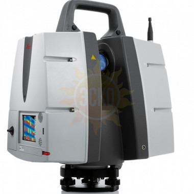
Among contact measuring instruments, coordinate measuring machines with a horizontal arm are the fastest to solve problems in the field of automated metrological control.
Mostovy Kim
Source: Metrology.news
Bridge Kim designed specifically for high -precision and complex measurements. They digitize depressions and holes of very small diameter. Design features of devices:
- heavy, usually granite base;
- vibration isolation system;
- Rigid construction to prevent various types of damage;
- range of interchangeable styli, gauges and probes for measuring accuracy and comparing the finished part with the basic software model.
Two versions: static work platform and movable bridge, or static bridge and movable platform.
Portal Kim
Source: Directindustry.com
Using portal Kim measure large -sized objects. The devices themselves are also large. Guides are made of rigid materials resistant to temperature changes and deformations. The open type of design simplifies the work: installation, direct measurement and movement of parts.
Optical 3D Scan
3D laser scanning
One of the key differences between probe and laser measurements is the ability to capture the shape of objects. Mechanical scanning does not give an idea of the shape of objects. When objects are digitized by a laser scanner, a point cloud is created, on the basis of which the software generates a three-dimensional detailed and high-precision model.
Source: whatech.com
Laser scanning is a non-contact technology, therefore it is widely used for remote quality control when working with fragile and easily deformable objects. Because lasers are coherent light sources, 3D laser scanners are virtually unaffected by environmental fluctuations.
Patterned illumination scanning
A light grid is directed to the scanned object, the cameras fix the shape of the light projection and calculate the coordinates of each point. Based on the information received, the software builds a digital model.
9
When it is necessary to scan hard-to-reach areas, such as channels and holes, scanners with structured illumination are complemented by hand-held measuring instruments.
Multisor devices
Source: Interestingengineering.com
Complex contact and contactless measurement technologies, multi -spokeswood includes the Silmary STRIONS:
- Possibility of high-precision measurements in hard-to-reach places - advantages of CMM;
- High speed and more information are the advantages of optical scanners.
The design of such devices is a 3D scanner, equipped with an additional probe with a sensor.
Source: metrology.news
The structure of multisensor machines does not have strict standards, so they may vary between manufacturers and depending on the application.
Robotic Coordinate Measuring Machines
Source: metrology.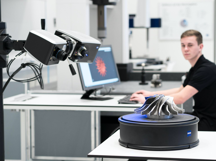 news
news
Devices work regardless of environmental conditions, always with the same high accuracy, without fatigue and days off. Robots are replacing humans in hazardous and hazardous production environments. Work with large and small objects.
CMM, optical scanner, probe and other control devices can be used as a sensor. Today's experience of use proves that any metrological measurements are available to robotic CMMs.
Cases using measuring equipment
SHIGE OF Modernization, DEWYS ENGINERING
Source: YouTu.be
052
The company was faced with the task of reconstructing a failed large cast gear from the gearbox. For the solution, a Faro Platinum Arm LLP V3 robotic 8-axis multisensor center equipped with mechanical and laser three-dimensional scanning functions was used. After digitizing and controlling the holes of the part, the data was collected and processed in the Geomagic Design X software. The created model was sent to Soildworks for further processing, then DeWys Engineering prepared a file with instructions for creating a copy of the gear on a gear hobbing machine.
quality control of large consumers, Computer Aided Technology
Source: Cati.com
9000 9000 BOB RENELLA, Complex, Underword, Office, which was carried out. batches of parts. In this regard, he was faced with the task of optimizing processes: reducing time costs without losing the accuracy of the check. Familiar technologies no longer suited the company: an operator was involved in checking every detail, there were losses of time and quality.
Computer Aided Technology was faced with a choice:
- Buy an additional inspection machine and bring in a new workforce for maintenance.
- Outsource some of the tests, which will increase the cost and possibly the quality of the measurements.
- Invest in more modern equipment.
The management settled on the last option. As a result of purchasing a set: wireless Creaform HandyProbe and two-chamber C-Track, the company received a number of advantages:
- The mobile scanner allowed the operator to work anywhere in the plant, which saved time and effort spent on transporting batches of goods to the inspection site.
- The size of parts to be tested is no longer limited by the capabilities of the old inspection machine.
The combination of Creaform HandyProbe and INNOVMETRIC's PolyWorks Inspector software solution has made the operator's job much easier. Now the specialist acts according to the algorithm proposed by the software in real time.
Inspection of a 10m Shaft Arm with ScanTech TrackScan and TrackProbe light pen in 15 minutes
0005
When the excavator is operating, heavy loads act on the bucket arm, as a result of which the bushings of the bucket shaft hole wear out intensively.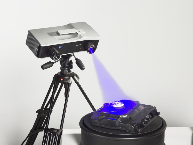 An increase in the diameter of the bucket shaft hole leads to an increase in the beating of the shaft in the lever hole, which subsequently leads to a breakdown of the equipment. Accordingly, regular inspection of the size of the lever holes prevents equipment failure. Buying a CMM to solve this problem is expensive and impractical, since such machines are installed permanently, and the transportation of large parts to the CMM installation site entails additional time and financial costs.
Source: 3d-scantech.com
It took 15 minutes to digitize, process the results, and check the quality of the 10-meter arm right on site. The specialists used the ScanTech TrackScan 3D scanner, created in partnership with the Norwegian manufacturer Metronor. The scanner works without markers, together with the TrackProbe light pen it makes high-precision measurements of holes of any depth and radius.
Results
Accordingly, the need for production to optimize quality control processes is growing: increasing speed and accuracy, reducing costs.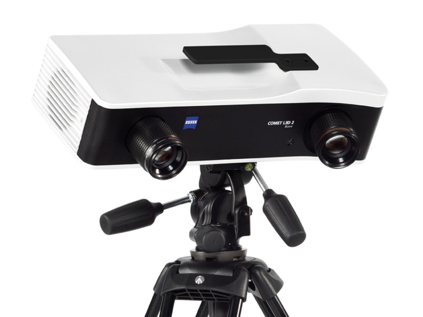
Learn more