3D printer quality
Blobs and Zits
Blobs and Zits
During your 3D print, the extruder must constantly stop and start extruding as it moves to different portions of the build platform. Most extruders are very good at producing a uniform extrusion while they are running, however, each time the extruder is turned off and on again, it can create extra variation. For example, if you look at the outer shell of your 3D print, you may notice a small mark on the surface that represents the location where the extruder started printing that section of plastic. The extruder had to start printing the outer shell of your 3D model at that specific location, and then it eventually returned to that location when the entire shell had been printed. These marks are commonly referred to as blobs or zits. As you can imagine, it is difficult to join two pieces of plastic together without leaving any mark whatsoever, but there are several tools in Simplify3D that can be used to minimize the appearance of these surface blemishes.
Common Solutions
Retraction and coasting settings
If you start to notice small defects on the surface of your print, the best way to diagnose what is causing them is to watch closely as each perimeter of your part is printed. Does the defect appear the moment the extruder starts printing the perimeter? Or does it only appear later when the perimeter is completed and the extruder is coming to a stop? If the defect appears right away at the beginning of the loop, then it’s possible your retraction settings need to be adjusted slightly. Click on “Edit Process Settings” and go to the Extruders tab. Right below the retraction distance, there is a setting labeled “Extra Restart Distance.” This option determines the difference between the retraction distance when the extruder is stopping and the priming distance that is used when the extruder is restarting. If you notice a surface defect right at the beginning of the perimeter, then your extruder is likely priming too much plastic. You can reduce the priming distance by entering a negative value for the extra restart distance. For example, if your retraction distance is 1.0mm, and the extra restart distance is -0.2mm (note the negative sign), then each time your extruder stops, it will retract 1.0mm of plastic. However, each time the extruder has to start extruding again, it will only push 0.8mm of plastic back into the nozzle. Adjust this setting until the defect no longer appears when the extruder initially begins printing the perimeter.
If the defect does not occur until the end of the perimeter when the extruder is coming to a stop, then there is a different setting to adjust. This setting is called coasting. You can find it right below the retraction settings on the Extruder tab. Coasting will turn off your extruder a short distance before the end of the perimeter to relieve the pressure that is built up within the nozzle. Enable this option and increase the value until you no longer notice a defect appearing at the end of each perimeter when the extruder is coming to a stop. Typically, a coasting distance between 0.2-0.5mm is enough to have a noticeable impact.
Avoid unnecessary retractions
The retraction and coasting settings mentioned above can help avoid defects each time the nozzle retracts, however, in some cases, it is better to simply avoid the retractions all together. This way the extruder never has to reverse direction and can continue a nice uniform extrusion. This is particularly important for machines that use a Bowden extruder, as the long distance between the extruder motor and the nozzle makes retractions more troublesome. To adjust the settings that control when a retraction takes place, go to the Advanced tab and look for the “Ooze Control Behavior” section. This section contains many useful settings that can modify the behavior of your 3D printer. As was mentioned in the Stringing or Oozing section, retractions are primarily used to prevent the nozzle from oozing as it moves between different parts of your print. However, if the nozzle is not going to cross an open space, the oozing that occurs will be on the inside of the model and won’t be visible from the outside. For this reason, many printers will have the “Only retract when crossing open spaces” option enabled to avoid unnecessary retractions.
Another related setting can be found in the “Movement Behavior” section. If your printer is only going to retract when crossing open spaces, then it would be beneficial to avoid these open spaces as much as possible. Simplify3D includes an extremely useful feature that can divert the travel path of the extruder to avoid crossing an outline perimeter. If the extruder can avoid crossing the outline by changing the travel path, then a retraction won’t be needed. To use this feature, simply enable the “Avoid crossing outline for travel movement” option.
Non-stationary retractions
Another extremely useful feature in Simplify3D is the ability to perform non-stationary retractions. This is particularly useful for bowden extruders that build up a lot of pressure inside the nozzle while printing. Typically when these types of machines stop extruding, the excess pressure is still likely to create a blob if the extruder is standing still.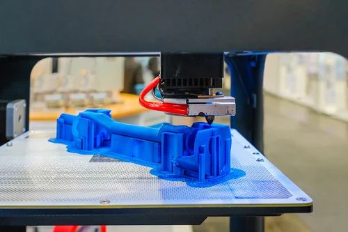 So Simplify3D has added a unique option that allows you to keep the nozzle moving while it performs its retraction. This means you are less likely to see a stationary blob since the extruder is constant moving during this process. To enable this option, we have to adjust a few settings. First, click “Edit Process Settings” and go to the Extruder tab. Make sure that the “Wipe Nozzle” option is enabled. This will tell the printer to wipe the nozzle at the end of each section when it stops printing. For the “Wipe Distance”, enter a value of 5mm as a good starting point. Next, go to the Advanced tab and enable the option labeled “Perform retraction during wipe movement”. This will prevent a stationary retraction, since the printer has now been instructed to wipe the nozzle while it retracts. This is a very powerful feature and a great option to try if you are still having trouble removing these defects from the surface of your print.
Choose the location of your start points
If you are still seeing some small defects on the surface of your print, Simplify3D also provides an option that can control the location of these points.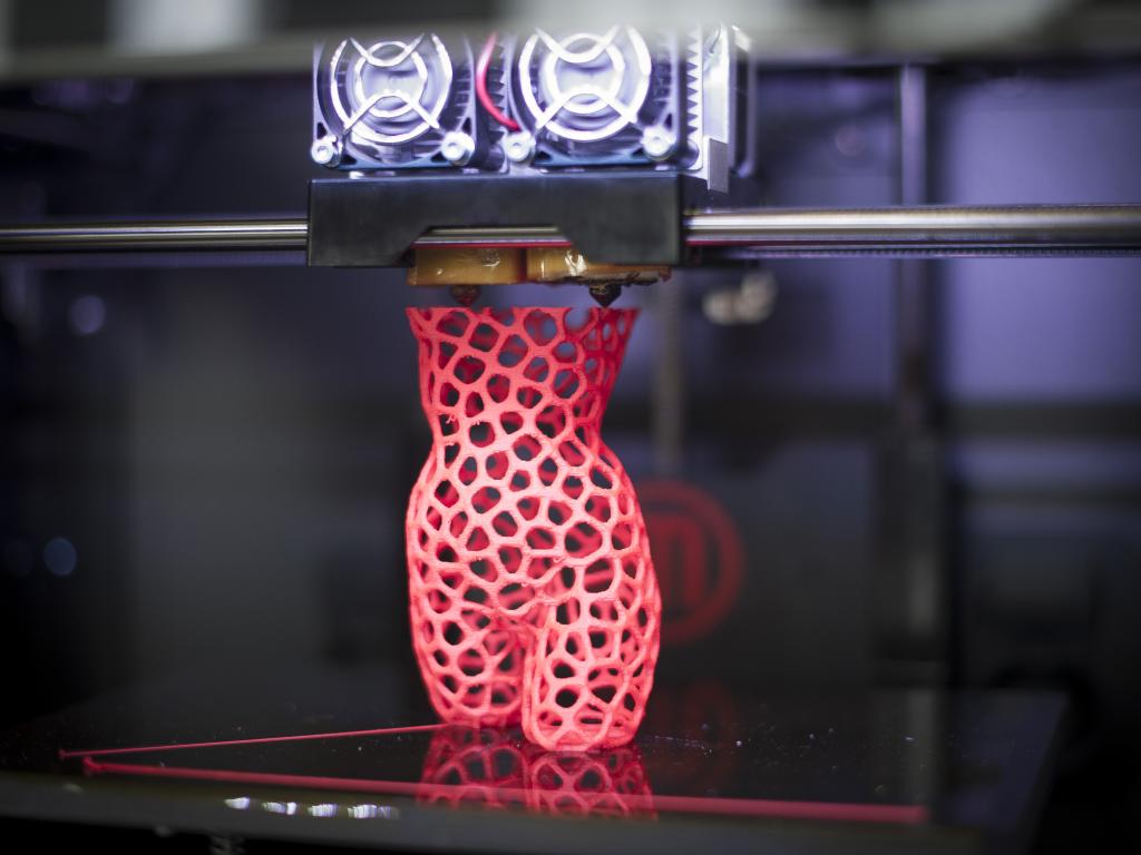 Click on “Edit Process Settings” and select the Layer tab. In most cases, the locations of these start points are chosen to optimize the printing speed. However, you also have the ability to randomize the placement of the start points or align them to a specific location. For example, if you were printing a statue, you could align all of the start points to be on the backside of the model so that they were not visible from the front. To do this, enable the “Choose start point that is closest to specific location” option and then enter the XY coordinate where you want the start points to be placed.
Related Topics
Stringing or Oozing
Stringing or Oozing
Stringing (otherwise known as oozing, whiskers, or “hairy” prints) occurs when small strings of plastic are left behind on a 3D printed model. This is typically due to plastic oozing out of the nozzle while the extruder is moving to a new location. Thankfully, there are several settings within Simplify3D that can help with this issue.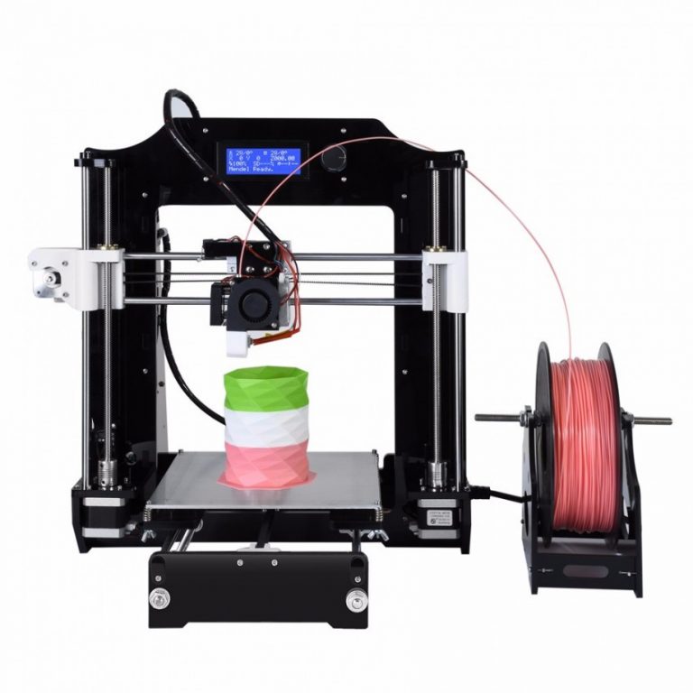 The most common setting that is used to combat excessive stringing is something that is known as retraction. If retraction is enabled, when the extruder is done printing one section of your model, the filament will be pulled backwards into the nozzle to act as a countermeasure against oozing. When it is time to begin printing again, the filament will be pushed back into the nozzle so that plastic once again begins extruding from the tip. To ensure retraction is enabled, click “Edit Process Settings” and click on the Extruder tab. Ensure that the retraction option is enabled for each of your extruders. In the sections below, we will discuss the important retraction settings as well as several other settings that can be used to combat stringing, such as the extruder temperature settings.
Common Solutions
Retraction distance
The most important retraction setting is the retraction distance. This determines how much plastic is pulled out of the nozzle. In general, the more plastic that is retracted from the nozzle, the less likely the nozzle is to ooze while moving. Most direct-drive extruders only require a retraction distance of 0.5-2.0mm, while some Bowden extruders may require a retraction distance as high as 15mm due to the longer distance between the extruder drive gear and the heated nozzle. If you encounter stringing with your prints, try increasing the retraction distance by 1mm and test again to see if the performance improves.
Retraction speed
The next retraction setting that you should check is the retraction speed. This determines how fast the filament is retracted from the nozzle. If you retract too slowly, the plastic will slowly ooze down through the nozzle and may start leaking before the extruder is done moving to its new destination. If you retract too quickly, the filament may separate from the hot plastic inside the nozzle, or the quick movement of the drive gear may even grind away pieces of your filament. There is usually a sweet spot somewhere between 1200-6000 mm/min (20-100 mm/s) where retraction performs best.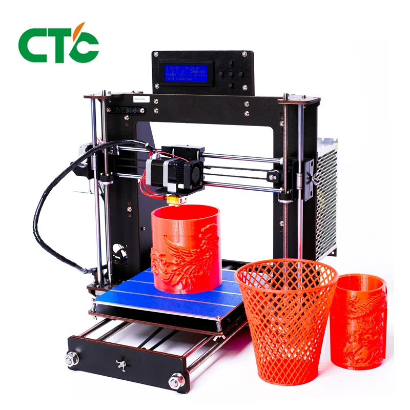 Thankfully, Simplify3D has already provided many pre-configured profiles that can give you a starting point for what retraction speed works best, but the ideal value can vary depending on the material that you are using, so you may want to experiment to see if different speeds decrease the amount of stringing that you see.
Temperature is too high
Once you have checked your retraction settings, the next most common cause for excessive stringing is the extruder temperature. If the temperature is too high, the plastic inside the nozzle will become less viscous and will leak out of the nozzle much more easily. However, if the temperature is too low, the plastic will still be somewhat solid and will have difficulty extruding from the nozzle. If you feel you have the correct retraction settings, but you are still encountering these issues, try decreasing your extruder temperature by 5-10 degrees. This can have a significant impact on the final print quality. You can adjust these settings by clicking “Edit Process Settings” and selecting the Temperature tab. Select your extruder from the list on the left, and then double-click on the temperature setpoint you wish to edit.
Long movements over open spaces
As we discussed above, stringing occurs when the extruder is moving between two different locations, and during that move, plastic starts to ooze out of the nozzle. The length of this movement can have a large impact on how much oozing takes place. Short moves may be quick enough that the plastic does not have time to ooze out of the nozzle. However, long movements are much more likely to create strings. Thankfully, Simplify3D includes an extremely useful feature that can help minimize the length of these movements. The software is smart enough that it can automatically adjust the travel path to make sure that nozzle has a very short distance to travel over an open space. In fact, in many cases, the software may be able to find a travel path that avoids crossing an open space all together! This means that there is no possibility to create a string, because the nozzle will always be on top of the solid plastic and will never travel outside the part. To use this feature, click on the Advanced tab and enable the “Avoid crossing outline for travel movement” option.
Movement Speed
Finally, you may also find that increasing the movement speed of your machine can also reduce the amount of time that the extruder can ooze when moving between parts. You can verify what movement speeds your machine is using by clicking on the Speeds tab of your process settings. The X/Y Axis Movement Speed represents the side-to-side travel speed, and is frequently directly related to the amount of time your extruder spends moving over open air. If your machine can handle moving at higher speeds, you may find that increasing this settings can also reduce stringing between parts.
Related Topics
Clarity, Accuracy & Tolerances in 3D Printing
Just because your 3D printer says it has "high resolution" does not mean it will produce accurate or sharp prints.
Understanding the meaning of the terms precision, clarity, and tolerance is a prerequisite for achieving quality 3D printing results, regardless of industry. In this article, we will analyze what these terms mean in the context of 3D printing.
Webinar
Want to learn how to use 3D printing for design? Watch our webinar and learn about the stereolithography (SLA) 3D printing process, different types of materials, and tips from experts on how to optimize your printing process to make it as efficient as possible.
Watch the webinar now
Let's start with some definitions: what is the difference between precision, clarity and tolerance? For each term, we will use a target - a common example for understanding these concepts, helping to visualize them.
Precision determines how close the measured value is to the true value. In the target example, the true value is the bullseye. The closer you are to the bullseye, the more accurate your throw. In the world of 3D printing, the true value is the dimensions of your CAD model. To what extent does a product made on a 3D printer correspond to a digital model?
Clarity corresponds to measurement reproducibility - how consistent are your hits on the target? Clarity only measures this reproducibility. You can always hit the same spot, but it doesn't have to be the bullseye. In 3D printing, this ultimately leads to reliability. Are you sure that you will get the expected results for each model produced by your printer?
In engineering terms, "clarity" is used to measure the reproducibility of results. Applied to materials for 3D printing, “clear” can mean the ability to manufacture complex geometries. For example, Formlabs Gray Pro Resin and Rigid Resin resins have a high "green modulus", or modulus of elasticity, that can successfully print thin and intricate details.
What accuracy is required in this case? This is determined by tolerances , which you define. How much wiggle room do you have based on the purpose of the model? What is the allowable variability in the closeness of the measurements to the exact ones? It depends on the specifics of your project. For example, a component with a dynamic mechanical assembly needs tighter tolerances than a conventional plastic housing.
If you're specifying tolerance, you'll probably need precision as well, so let's assume we're measuring bullseye accuracy. Earlier we called the shots in the picture with the target on the right fuzzy.
But if you have wide tolerances, this may not be a problem. The shots are not as close to each other as they are on the target on the left, but if the acceptable range of sharpness is ±2.5 hoops, then you are not out of range.
As a rule, achieving and maintaining tighter tolerances entails higher production and quality control costs.
White Paper
Tolerance and fit are important concepts that engineers use to optimize mechanical functionality and manufacturing cost. Use this white paper when designing 3D printed workpieces or as a starting point when designing a fit between parts printed with Formlabs Tough Resin or Durable Resin.
Download white paper
There are many factors to consider when thinking about precision and clarity in 3D printing, but it's also important to get your needs right.
For example, a sharp but inaccurate 3D printer may be optimal for some applications. An inexpensive Fused Deposition Modeling (FDM) machine will produce less accurate parts, but for a teacher teaching students 3D printing for the first time, the exact fit of the student's CAD model doesn't matter as much.
But if the printer performs to specifications and delivers the quality expected of it within the tolerances the user is accustomed to, this may be sufficient for successful operation.
Check out our detailed guide comparing FDM vs. SLA 3D printers to see how they differ in terms of print quality, materials, application, workflow, speed, cost, and more.
There are four main factors that affect the accuracy and clarity of a 3D printer:
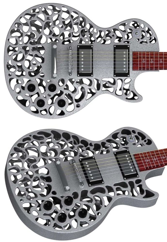
3D printing is a type of additive manufacturing where models are made layer by layer. Violations can potentially occur in every layer. The layering process affects the level of clarity (or reproducibility) of each layer's accuracy. For example, when printing on an FDM printer, layers are formed using a nozzle, which cannot provide the same accuracy for obtaining complex parts as other 3D printing technologies.
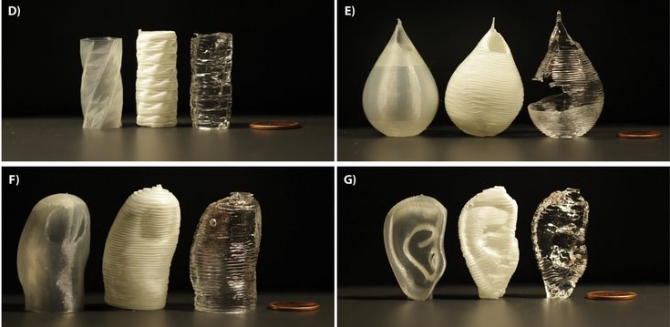
Because layers are extruded, FDM models often show layer lines and inaccuracies around complex features. (Left is an FDM printed part, right is a SLA printed part.)
In stereolithography (SLA) 3D printing, each layer is formed by curing a liquid polymer with a high-precision laser, resulting in more detailed models and achieve high quality on a consistent basis.
Selective Laser Sintering (SLS) also uses a laser to accurately convert nylon powder into lightweight, durable parts.
The specifications of a 3D printer alone do not give an idea of the accuracy of the models produced. One of the common misconceptions about the accuracy of various 3D printing technologies is describing XY resolution as dimensional accuracy.
For digital light processing (DLP) printers, the XY resolution corresponds to the projected pixel size.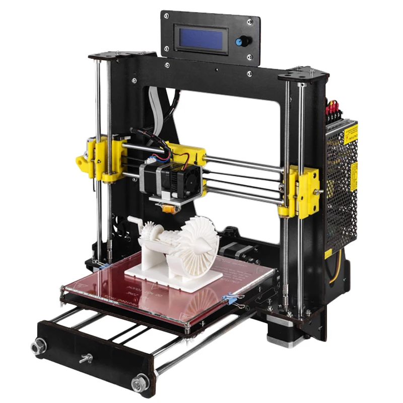 Many 3D printer systems use this projected pixel size, or XY resolution, as a general measure of accuracy, such as stating that with a projected pixel size of 75 µm, the accuracy of the device is ±75 µm.
Check out our guide to SLA and DLP 3D printing, where we talk about the features of the two processes and how they differ.
But this data does not affect the accuracy of the printed model. There are many other sources of error that affect accuracy, from components and calibration to materials and post-processing. We will consider the last two factors in more detail.
The best way to evaluate a 3D printer is to study the models printed on it.
Accuracy may also vary depending on the media you are printing on and the mechanical properties of those media, which can also affect the likelihood of model warping.
Formlabs Rigid Resin has a high "green modulus", or modulus of elasticity before final polymerization, which allows you to print very thin models with high definition and reliability.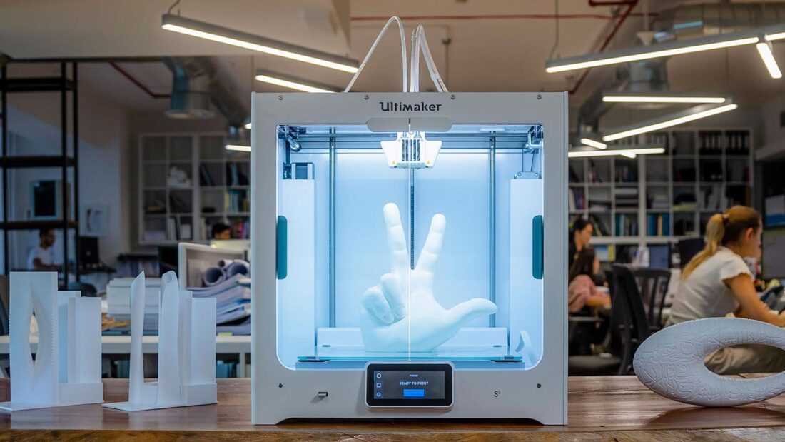
But, again, it all depends on your goals. For example, in dentistry, the accuracy of 3D printed models is critical. But if you're printing a concept model, chances are you just want to get a general idea of the physical product, and accuracy won't be that important.
Margins, mold surfaces, and contact surfaces printed with Formlabs Model Resin are accurate to within ±35 µm of the digital model at over 80% of surface points when printed at 25 µm settings. The overall accuracy across the entire arc is within ±100 µm on 80% of surfaces when printed with settings of 25 or 50 µm.
3D printed models often need to be cured, which in turn often leads to shrinkage. This is normal for any part made using SLA or DLP 3D printing. Depending on the printer, this phenomenon may need to be considered in the design. PreForm, Formlabs' free file preparation software, automatically compensates for this shrinkage, ensuring that the final cured models are the same dimensions as the original CAD model.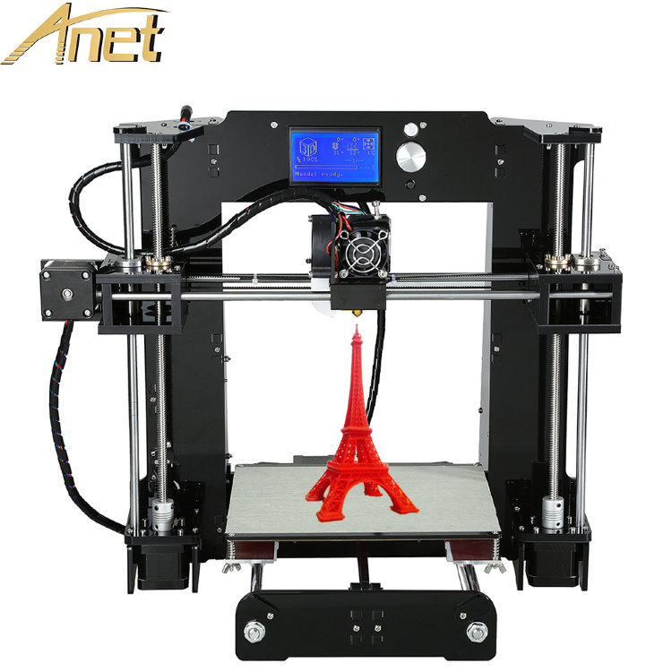
How does the final polymerization work? Learn more about the theory behind the process and see efficient ways to successfully finish curing models made with stereolithographic 3D printers.
Producing quality models on a 3D printer requires attention not only to the printer itself, but to the entire production process.
The final result may be affected by the print preparation software, post-processing materials and tools used. In general, integrated systems designed to work together produce more reliable results.
Unlike machining, where parts are progressively improved to tighter tolerances, 3D printing has only one automated manufacturing step. While complex coating adds cost to processes such as CNC milling, creating complex features with 3D printing is essentially free, although the tolerances of a 3D printed model cannot be automatically improved beyond the capabilities of the printer. without resorting to subtractive methods.
3D printing is a great option if you have rough, complex features such as undercuts and complex surfaces, and don't necessarily need surface accuracy better than ±0.125mm (standard machining). Tolerances beyond standard machining must be achieved using subtractive methods, either through manual or machine processing, for both 3D printed and CNC models.
SLA has the highest tolerance compared to other commercial 3D printing technologies. The tolerances for stereolithographic 3D printing are somewhere between standard and precision machining.
In general, more malleable stereolithography materials will have a wider tolerance zone than more rigid materials. Designing subassembly parts for tolerance and fit reduces post-processing time and simplifies assembly, as well as reduces material costs per iteration.
There are many other factors to consider when evaluating 3D printers. Should your models be isotropic? What mechanical properties should your models (and, accordingly, the materials from which they are made) have? The best place to start is to get familiar with the physical models printed on a 3D printer. Order a free material sample from Formlabs of your choice and see for yourself the quality of your stereolithography print.
Request a sample 3D model
The real accuracy of a 3D printer: what can be printed
The accuracy of a 3D printer
The accuracy of a 3D printer is one of the most important parameters that buyers first of all pay attention to. It is not surprising: the detailing of future plastic products primarily depends on this item. But everyone wants to get the highest quality models. 3D printer accuracy refers to the minimum layer height applied during 3D printing. It would seem that everything is very simple. The higher the print accuracy, the better the quality of the generated patterns. However, the stated accuracy of a 3D printer may differ from the actual quality of a 3D print. Why is this happening? There can be many reasons. Let's try to understand them and clarify some incomprehensible points.
3D printing accuracy
As mentioned above, 3D printing accuracy is the minimum allowable layer height applied by a 3D printer. Modern FDM 3D printers can produce quality down to 20 microns, which is actually very good. But in order to actually obtain samples of such accuracy, certain conditions must be observed.
- First, you need to correctly set all the print settings. And this is not an easy task, given that for each specific type of plastic and 3D model, the parameters are individual.
- Secondly, you need to monitor the correct operation of the 3D printer, table calibration, temperature conditions.
- Thirdly, you should choose the best plastic for 3D printing. The properties of different materials can vary, and not every plastic will give the required accuracy of a 3D printer.
These are the main points to pay attention to in the pursuit of high-precision 3D printing, but not the only ones. Let's continue to open the topic.
Other questions and answers about 3D printers and 3D printing:
Printing accuracy on a 3D printer
First of all, the accuracy of printing on a 3D printer depends on the 3D printer itself.