3D printer mosfet wiring
Howto Connect your Hotbed (and or extruder) to a Mosfet [3DPrint.Wiki]
Howto Connect your Hotbed (and or extruder) to a Mosfet
IMPORTANT: I have seen people trying to (re-)sell these Mosfet units with a HUGE profit on EBAY while referring to this page for installation schematics, go shop around, they don't need to be more expensive than around €5 to €10 ($5 to $10) incl PP.
Click here for an example of some prices
Why
The idea is pretty simple: The high current of the hotbed brings multiple problems to your mainboard. All the current for the bed has to go through the one connector in addition to all the other current for the hotend, the steppers and the logic units, the default connectors are not rated for the current that goes through them when printing. Things like in the picture below happen to almost every printer at one time in its life …..
←– connector and corresponding plug —>
(EDIT: the latest version of the control board has newer/different type connectors fitted they are safer, but if not connected properly even they CAN and WILL melt, *remember transition resistance in combination with high(er) currents equals heat development)
Removing the hotbed bed current from the mainboard, significantly reduces stress on your mainboard (connectors).
Another benefit, it will allow you to use a second PSU for bed power (12 or 24 volts).
What you need
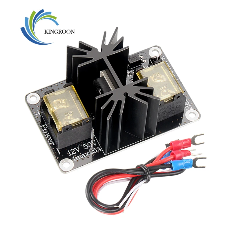
a MOSFET unit like this, a 2 pin JST connector with some wire and some thicker wire(s) AWG 16 or AWG 14 (1,5 mm2 or 2,5 mm2)
Note: Some mosfets are sold with the signal wire, some without, check if you need to buy a separate one.
3D-Printer-Parts-General-Add-on-Heated-Bed-Power-Expansion-Module-High-Power-Module-expansion-boardon banggood.com
Question: Can I use a mechanical relays too? Answer: Theoretically...yes, but mechanical switches are generally not meant for the large number of repeated on/off cycles as your printer will generate them.
How to install
A special bracket to mount your ANET mainboard and 1 mosfet unit, you can find here https://www.thingiverse.com/thing:1857006
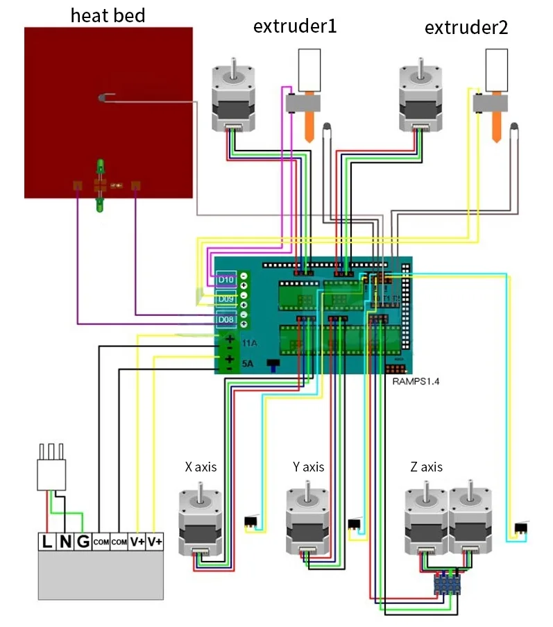
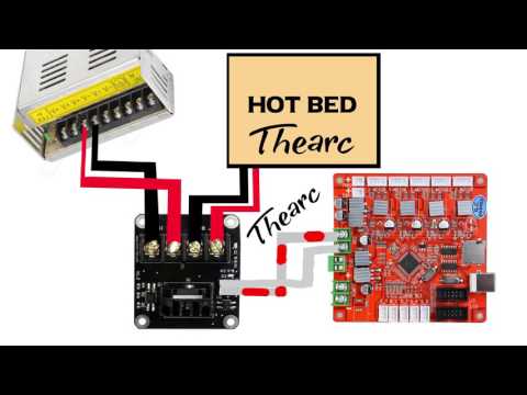
NOTE: More than one version of the ANET controlboard is being shipped from China (with and without version nummers), always check for + and - (polarity) on the boards.* RED = + (on psu marked as +V ) * BLACK = - (on psu marked as -V or COM )
NOTE: I used an easy way to wire this using the stock 12 volts wire and without cutting it, just removing about 1 cm of the insulation (to connect the mosfetboard), ran it from psu to mosfetboard to controlboard.(applies if you use 1 psu only) Other people might want to use 2 sets of wires, 1 for controlboard and the extra set of wires from PSU to mosfetboard.
unplug your printer's power cord
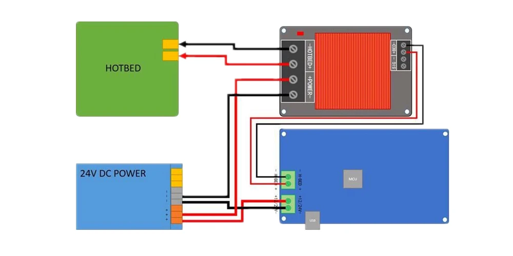
remove the power-cables of the heated bed from the mainboard and attach them to the power output of the MOSFET unit
Connect 2 wires from the bed output of the mainboard to the control input of the MOSFET (polarity DOES NOT MATTER for this signalwire)
Connect 2 wires from the PSU (either the same as the printer, or a second PSU) to the power input if the MOSFET unit (Here polarity DOES MATTER)
check twice against the graphic
For the signalwire there has been some confusion
some people claim polarity matters they are right sometimes some mosfets are polarity sensitive.
For the mosfet unit shown in the 2 pictures here, POLARITY DOES NOT MATTER, check them side by side with the signal wire connected both ways.
In both pictures the hotbed was set to preheat PLA, both led blue (D2) and Red (D1) light up and everything functions as it should. In the photo's below you can see the “bridge-rectifier” on the mosfet (just to the right of the white plug) wich corrects “wrong” connection of this wire!
Apply a second PSU ( 12 or 24 volts)
If you want your HOTBED to heatup faster you can add a second power supply unit to your printer.
Disconnect the wires from the PSU to the Mosfet Unit and apply them to the second PSU.
The heating element that came with the Anet A8 will perform ok with an increase of the (PSU 1) Voltage to 14 Volts. This will help the bed heat up significantly faster.
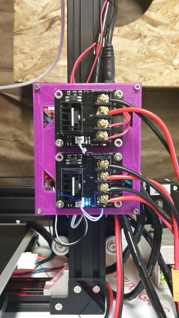
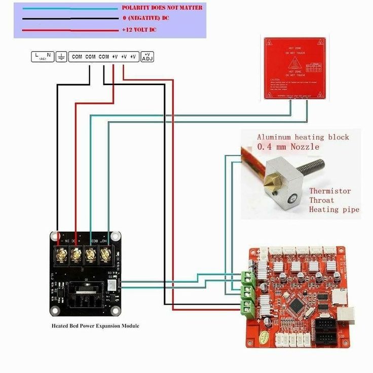
Apply a second Mosfet (for the extruder)
Eventhough in my opinion it is not really necessary, you might want to decide you want to use a 2nd mosfet for your extruder as well, here is a schematic you might find usefull
Of course you can use 1 (upgraded) PSU for all the 12 volts wires if you choose to
Note: ( RED = + ) , ( BLACK = - ) , ( GRAY = polarity does not matter ) , ( TEAL = thermistor wires )
Increasing Voltage on the (stock) PSU
Note: This does NOT apply to an ATX PSU! You cannot change the voltage output on these, don't try.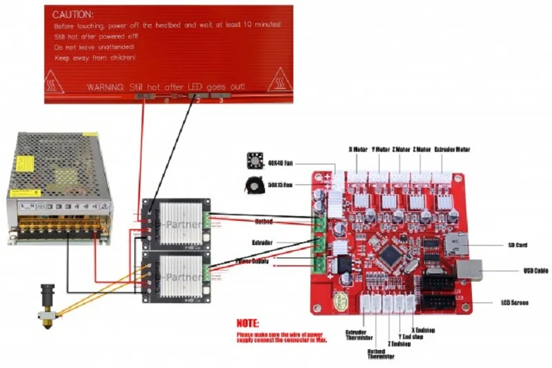
Near the power terminals, either on the left or the right of the terminals, is a small dial marked “ADJ +V”. Rotate it clockwise to increase voltage, and counter-clockwise to decrease it.
Always disconnect your power supply before making adjustments!
Check the voltage between one of the + and one of the - terminals, using a multimeter set for voltage DC.
PSU combinations
There are a lot of combinations possible
1 x 12 volts PSU
NOTE: This is the standard setup
2 x 12 volts PSU, of the one used for the heatbed you could raise the voltage to circa 14 volts
NOTE: If you have an ATX-Power supply laying around, use the "STOCK PSU" for the hotbed and the ATX for the controlboard and steppermotors.
Since there are 1 million different ATX PSU's, i will give some “general” things for you to consider only. No specifics about ONE PSU.
Check the ATX PSU you plan to use for a label like the orange one in the picture and check for maximum currents it can supply.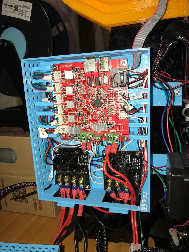 Note that using multiple voltage outputs at the same time means less available current for the separate outputs than stated as maximum sometimes.
- For easy connecting your ATX Power Supply Unit, you could use a breakoutboard like in the picture, check your PSU for maximum power (Amps) and order some extra fuses to replace the stock 5 amp fuses that come with the unit, if you plan to draw higher currents through the breakoutboard.
An other way is to just short the green (PS-ON) and black (GROUND) wire in the 20/24 connector to make the PSU be always ON. And use the wires from the wireloom as you need them. Just make sure the specific wires are designed to supply the current you need.
1x 12 volts + 1 x 24 volts, The 12 volts one is used to power the mainboard extruder and steppermotors, the 24 volts powers the heat bed (through the mosfet)
NOTE: Make sure you use the 24 volts connections on the heater
12 volts PSU + 24 volts PSU combination
The heating element in your HOTBED (as seen in the picture below) can be wired to support 12 or 24 volts connection.
The schematic printed on the surface shows pin 1 2 and 3 representation of the element →
If wired for 12 volts, the element is doubled up, resulting in less resistance/higher current/slower heating and less poweroutput.
If wired for 24 volts, the element is connected from both ends only resulting in higher resistance/lower current/faster heating higher poweroutput.
NOTE: There is more than one model of heating element available in the market, before you start any work check which one you have and if you can use the 24 volts option.
Do the math....
V=R*I (Voltage equals current multiplied by resistance), P=V*I (Power output equals Voltage multiplied by current)
HOTBED 12 Volt con. resistance betw 1.0-1.2 Ω (work with 1.1 Ω)
• I=V/R the current drawn at 12 Volts is 12/1.1= 10.9 Ampere
• P=V*I Power output at 12 Volts is 12*10.9= 130.9 Watts
HOTBED 14 Volts con. resistance betw 1. 0-1.2 Ω (work with 1.1 Ω)
• I=V/R the current drawn at 14 Volts is 14/1.1= 12.7 Ampere
• P=V*I Power output at 14 Volts is 14*12.7= 178.2 Watts
HOTBED 24 volts con. resistance betw 3-3.4 Ω (work with 3.2 Ω)
• I=V/R the current drawn at 24 Volts is 24/3.2= 7.5 Ampere
• P=V*I Power output at 24 Volts is 24*7.5= 180.0 Watts
[GUIDE] Install a mosfet between the power supply and the heated plate
Guides Upgrade
Posted on Author easy3dhome Comment(1)
Post Views: 886
Why install a Mosfet
If you’re new to 3D printing and you’re deciding to buy a printer, or you’ve just finished assembling it, you’ve surely heard of the Mosfet, and you’re wondering: Why should I install a mosfet?
The basic idea is quite simple. The power consumption used to heat the dish goes all through the motherboard, and it’s not a good thing. All the power needed to heat the bed must pass through a single connector. This unique connector must also serve all other parts such as the hotend, steppers and logical drives. The standard connectors are then not sized and designed to be crossed by the energy needed to heat a 30×30 plate to 110°C. So if you want to deal with long prints with the hot plate or you are equipped, or sooner or later you will have to deal with a small fire.
Luckily when it happened to me, the fire extinguished itself. I wasn’t near the printer and there was nothing I could have done. Anyway after this experience I immediately wanted to install a mosfet to my printer!
I talk of heated plate because it is the bed that requires most of the energy. The heating cartridge of hotends normally reaches 40w, more rarely 60w. The board as a whole needs another 50/60 w to power the microcontrollers and the display. Once the set temperature is reached, the energy required by the heating cartridge becomes intermittent and then decreases again. This brings the average consumption of a printer to work with the plate off to about 80/90 watts/hour. If our power supply is 360w (average size), then we see that more than 250w are hot bed paneling.
So by removing the bed current from the motherboard, you significantly reduce the stress on the motherboard connectors. If wanted we could install a mosfet for the Hotend even if with such low consumption I do not know if it is worth it.
Material required for this purpose:
- Mosfet
- Coloured electric cable
Install a mosfet
For the installation you can certainly start by printing a special bracket to mount the mosfet attached to the card or separate. You can find lots of them on Thingiverse
NOTE: always check the polarities + and – on the cards.
* RED = + (on psu marked as + V)
* BLACK = – (on psu marked -V or COM)
Now act as follows:
- Disconnect the printer power.
- Remove heated bed power cables from the motherboard and connect them to the output power of the MOSFET unit.
- Connect the 2 wires from the motherboard bed output to the MOSFET control input.
- Connect the 2 wires from the PSU to the power input of the MOSFET unit.
Even if the signal is said that it is not important the polarity does not cost anything to put it right, sometimes some mosfets are sensitive to polarity.
I hope that this mini guide has clarified some doubts both on the usefulness and on the installation of the mosfet. Electricity is no joke!
If you have found this post useful, please LIKE on Easy 3D Home Facebook’s page to receive updates on all the news of the Blog! You can find other guides about 3D in our Guides section!
Like this:
Like Loading...
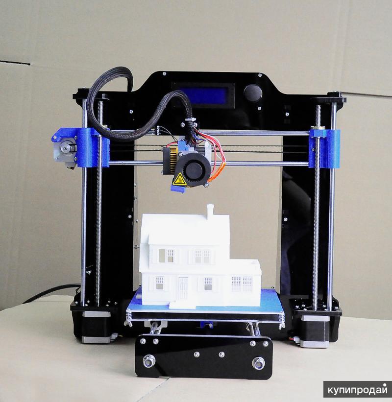
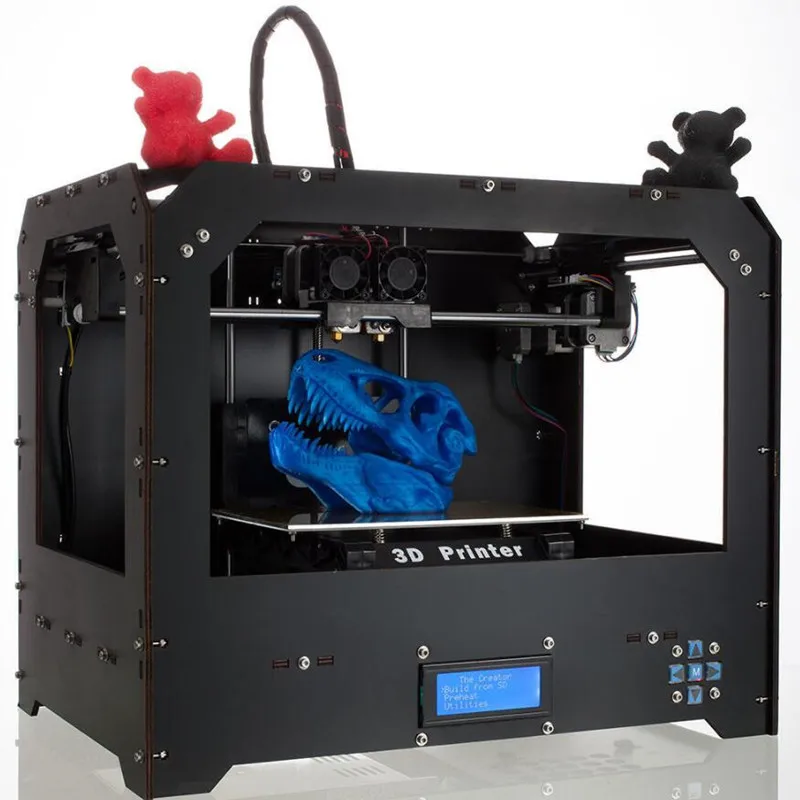
Building a home 3D printer with your own hands: recommendations from personal experience
3D printing and assembly of 3D printers is my hobby and passion. Here I will not share detailed diagrams and drawings, there are more than enough of them on specialized resources. The main goal of this material is to tell you where to start, where to dig and how to avoid mistakes in the process of assembling a home 3D printer. Perhaps one of the readers will be inspired by applied engineering achievements.
Why do you need a 3D printer? Use cases
I first came across the idea of 3D printing back in the 90s when I was watching the Star Trek series. I remember how impressed I was by the moment when the heroes of the cult series printed the things they needed during their journey right on board their starship. They printed anything: from shoes to tools. I thought it would be great someday to have such a thing too. Then it all seemed something incredible. Outside the window is the gloomy 90s, and the Nokia with a monochrome screen was the pinnacle of progress, accessible only to a select few.
Years passed, everything changed.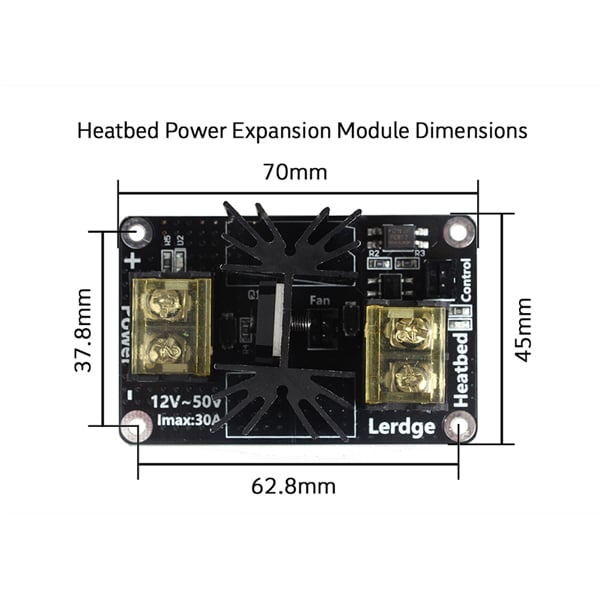 Around 2010, the first working models of 3D printers began to appear on sale. Yesterday's fantasy has become a reality. However, the cost of such solutions, to put it mildly, discouraged. But the IT industry would not be itself without an inquisitive community, where there is an active exchange of knowledge and experience and who just let them delve into the brains and giblets of new hardware and software. So, drawings and diagrams of printers began to surface more and more often on the Web. Today, the most informative and voluminous resource on the topic of assembling 3D printers is RepRap - this is a huge knowledge base that contains detailed guides for creating a wide variety of models of these machines.
I assembled the first printer about five years ago. My personal motivation to build my own device is quite prosaic and based on several factors. Firstly, there was an opportunity to try to realize the old dream of having your own device, inspired by a fantasy series. The second factor is that sometimes it was necessary to repair some household items (for example, a baby stroller, car elements, household appliances and other small things), but the necessary parts could not be found. Well, the third aspect of the application is "near-working". On the printer, I make cases for various IoT devices that I assemble at home.
Agree, it is better to place your device based on Raspberry Pi or Arduino in an aesthetically pleasing "body", which is not a shame to put in an apartment or take to the office, than to organize components, for example, in a plastic bowl for food. And yes, you can print parts to build other printers :)
There are a lot of scenarios for using 3D printers. I think everyone can find something of their own.
A complex part in terms of drawing that I printed on my printer. Yes, it's just a figurine, but it has many small elements
Ready solution vs custom assembly
When a technology has been tested, its value in the market decreases markedly. The same thing happened in the world of 3D printers. If earlier a ready-made solution cost simply sky-high money, then today acquiring such a machine is more humane for the wallet, but nevertheless not the most affordable for an enthusiast. There are a number of solutions already assembled and ready for home use on the market, their price range ranges from $500-700 (not the best options) to infinity (adequate solutions start from a price tag of about $1000). Yes, there are options for $150, but we, for understandable, I hope, reasons, will not dwell on them.
In short, there are three cases to consider a finished assembly:
- when you plan to print not much and rarely;
- when print accuracy is critical;
- you need to print molds for mass production of parts.
There are several obvious advantages to self-assembly. The first and most important is cost. Buying all the necessary components will cost you a maximum of a couple of hundred dollars. In return, you will receive a complete 3D printing solution with the quality of manufactured products acceptable for domestic needs. The second advantage is that by assembling the printer yourself, you will understand the principles of its design and operation. Believe me, this knowledge will be useful to you during the operation of even an expensive ready-made solution - any 3D printer needs to be serviced regularly, and it can be difficult to do this without understanding the basics.
The main disadvantage of assembly is the need for a large amount of time. I spent about 150 hours on my first build.
What you need to assemble the printer yourself
The most important thing here is the presence of desire. As for any special skills, then, by and large, in order to assemble your first printer, the ability to solder or write code is not critical. Of course, understanding the basics of radio electronics and basic skills in the field of mechanics (that is, "straight hands") will greatly simplify the task and reduce the amount of time that needs to be spent on assembly.
Also, to start we need a mandatory set of parts:
- Extruder is the element that is directly responsible for printing, the print head.
 There are many options on the market, but for a budget build, I recommend the MK8. Of the minuses: it will not be possible to print with plastics that require high temperatures, there is noticeable overheating during intensive work, which can damage the element. If the budget allows, then you can look at MK10 - all the minuses are taken into account there.
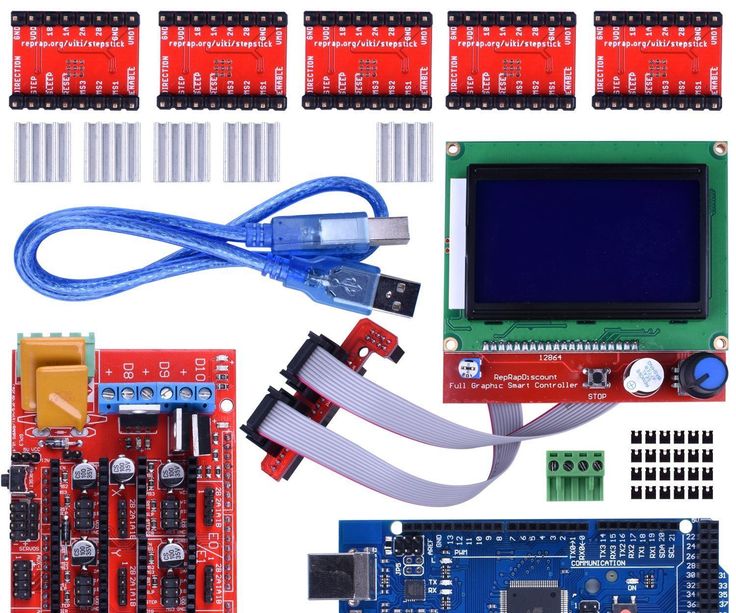
 - Processor board. The familiar Arduino Mega is well suited. I didn't notice any downsides to this solution, but you can spend a couple of dollars more and get something more powerful, with a reserve for the future.
- Control board. I'm using RAMPS 1.4 which works great with the Arduino Mega. A more expensive but more reliable board is Shield, which already combines a processor board and a control board. In modern realities, I recommend paying attention to it. In addition to it, you need to purchase at least 5 microstep stepper motor controllers, for example - A4988. And it's better to have a couple of these in stock for replacement.
- Heated table. This is the part where the printed element will be located. Heating is necessary due to the fact that most plastics will not adhere to a cold surface. For example, for printing with PLA plastic, the required surface temperature of the table is 60-80°C, for ABS - 110-130°C, and for polycarbonate it will be even higher
There are also two options for choosing a table - cheaper and more expensive. Cheaper options are essentially printed circuit boards with preheated wiring. To operate on this type of table, you will need to put borosilicate glass, which will scratch and crack during operation. Therefore, the best solution is an aluminum table. - Stepper motors. Most models, including the i2 and i3, use NEMA 17 size motors, two for the Z axis and one each for the X and Y axes. Finished extruders usually come with their own stepper motor. It is better to take powerful motors with a current in the motor winding of 1A or more, so that there is enough power to lift the extruder and print without skipping steps at high speed.
- Basic set of plastic fasteners.
- Belt and gears to drive it.
Examples of elements appearance: 1) MK8 extruder; 2) Arduino processor board; 3) RAMPS control board; 4) motor controllers; 5) aluminum heated table; 6) NEMA 17 stepper motor; 7) a set of plastic fasteners; 8) drive gears; 9) drive belt
This is a list of items to be purchased. Hardcore users can assemble some of them themselves, but for beginners, I strongly recommend purchasing ready-made solutions.
Yes, you will also need various small things (studs, bearings, nuts, bolts, washers ...) to assemble the case. In practice, it turned out that using a standard m8 stud leads to low printing accuracy on the Z axis. I would recommend immediately replacing it with a trapezoid of the same size.
M8 trapezoid stud for Z axis, which will save you a lot of time and nerves. Available for order on all major online platforms
You also need to purchase customized plastic parts for the X axis, such as these from the MendelMax retrofit kit.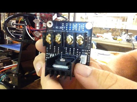
Most parts available at your local hardware store. On RepRap you can find a complete list of necessary little things with all sizes and patterns. The kit you need will depend on the choice of platform (we'll talk about platforms later).
What's the price
Before delving into some aspects of the assembly, let's figure out how much such entertainment will cost for your wallet. Below is a list of parts required for purchase with an average price.
Platform selection
The community has already developed a number of different platforms for assembling printers - the most optimal case designs and the location of the main elements, so you do not have to reinvent the wheel.
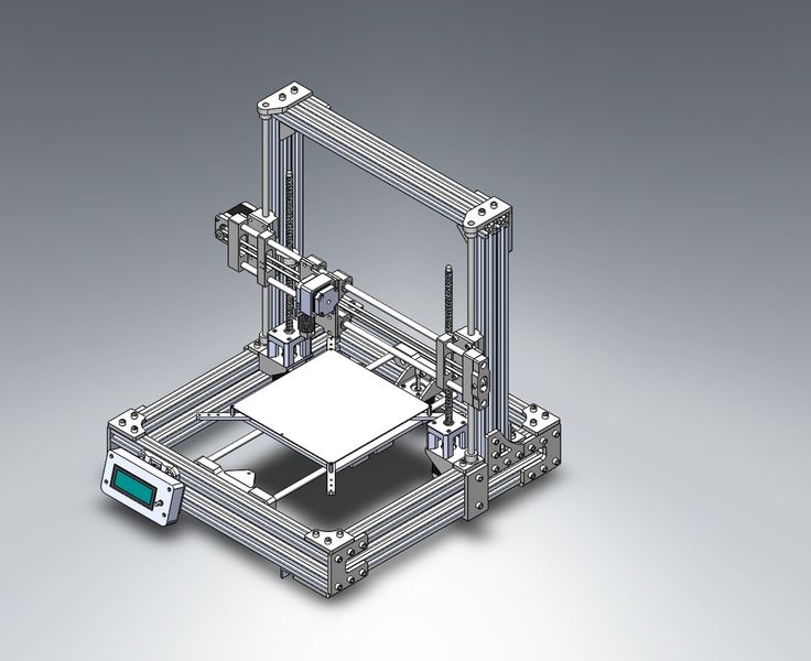
i2 and i3 are key platforms for self-assembly printer enclosures. There are also many modifications of them with various improvements, but for beginners, these two classic platforms should be considered, since they do not require special skills and fine-tuning.
Actually, illustration of platforms: 1) i2 platform; 2) i3 platform
On the plus side of i2: it has a more reliable and stable design, although it is a little more difficult to assemble; more opportunities for further customization.
The i3 variant requires more special plastic parts to be purchased separately and has a slow print speed. However, it is easier to assemble and maintain, and has a more aesthetically pleasing appearance. You will have to pay for simplicity with the quality of printed parts - the body has less stability than i2, which can affect print accuracy.
Personally, I started my experiments in assembling printers from the i2 platform. She will be discussed further.
Assembly steps, challenges and improvements
In this block, I will only touch on the key assembly steps using the i2 platform as an example. Full step by step instructions can be found here.
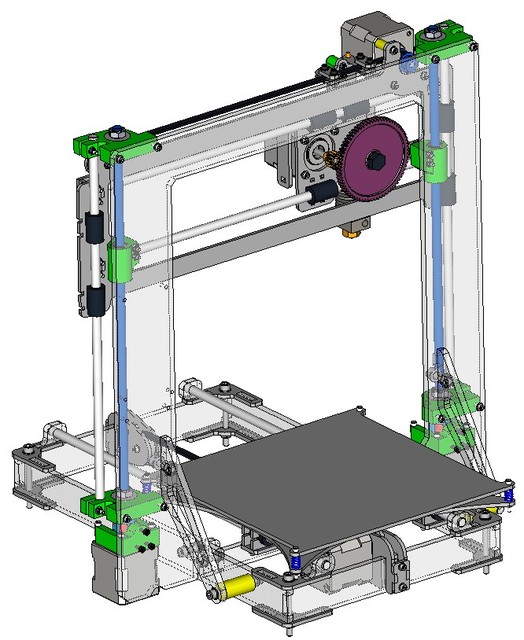
The general scheme of all the main components looks something like this. There is nothing particularly complicated here:
I also recommend adding a display to your design. Yes, you can easily do without this element when performing operations on a PC, but it will be much more convenient to work with the printer this way.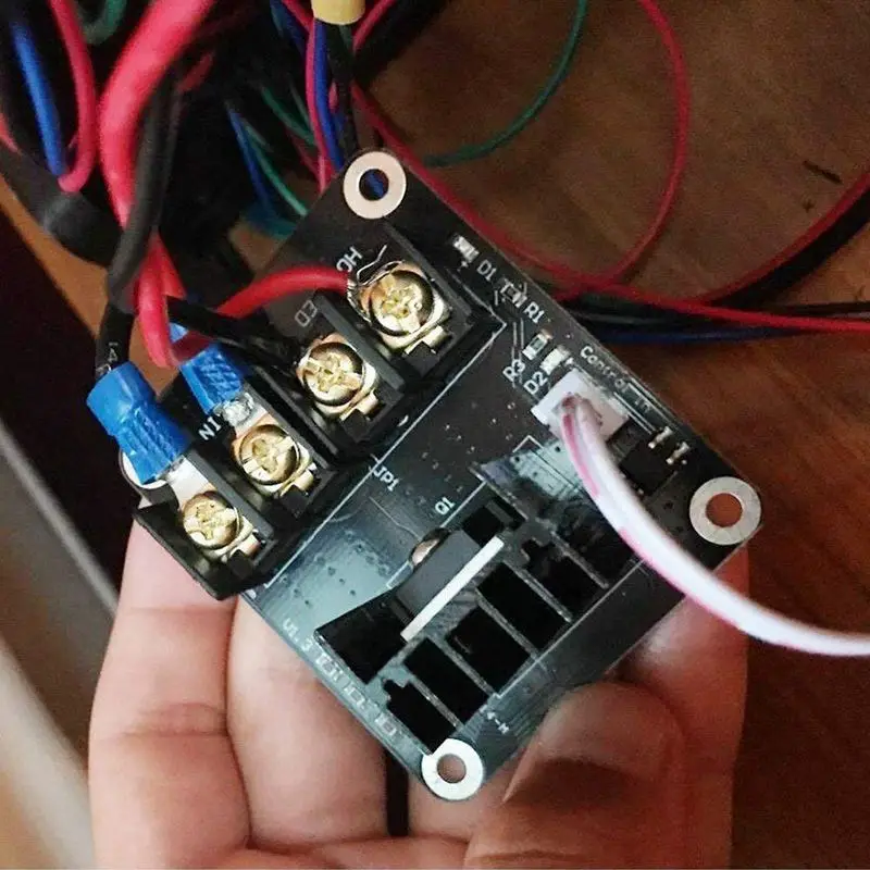
Understanding how all components will be connected, let's move on to the mechanical part, where we have two main elements - a frame and a coordinate machine.
Assembling the frame
Detailed frame assembly instructions are available on RepRap. Of the important nuances - you will need a set of plastic parts (I already talked about this above, but I'd better repeat it), which you can either purchase separately or ask your comrades who already have a 3D printer to print.
The frame of the i2 is quite stable thanks to its trapezoid shape.
This is how the frame looks like with parts already partially installed. For greater rigidity, I reinforced the structure with plywood sheets
Coordinate machine
An extruder is attached to this part. The stepper motors shown in the diagram above are responsible for its movement. After installation, calibration is required along all major axes.
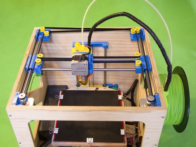
Important - you will need to purchase (or make your own) a carriage for moving the extruder and a mount for the drive belt. Drive belt I recommend GT2.
The carriage printed by the printer from the previous picture after it has been assembled. The part already has LM8UU bearings for guides and belt mount (top)
Calibration and adjustment
So, we completed the assembly process (as I said, it took me 150 hours) - the frame was assembled, the machine was installed. Now another important step is the calibration of this very machine and extruder. Here, too, there are small subtleties.
Setting up the machine
I recommend calibrating the machine with an electronic caliper. Do not be stingy with its purchase - you will save a lot of time and nerves in the process.
The screenshot below shows the correct constants for the Marlin firmware, which must be selected in order to set the correct number of steps per unit of measure. We calculate the coefficient, multiply it, substitute it into the firmware, and then upload it to the board.
Marlin 9 firmware constants0022
For high-quality calibration, I recommend relying on larger numbers in measurements - take not 1-1.5 cm, but about 10. So the error will be more noticeable, and it will become easier to correct it.
Calibrating the extruder
When the frame is assembled, the machine is calibrated, we start setting up the extruder. Here, too, everything is not so simple. The main task of this operation is to correctly adjust the supply of plastic.
If underfeeding, the printed test item will have noticeable gaps, like test die 1. Conversely, the result will look bloated if plastic is overfed (dice 2)
Getting Started Printing
It remains for us to run some CAD or download ready-made .stl, which describe the structure of the printed material. Next, this structure needs to be converted into a set of commands understandable to our printer.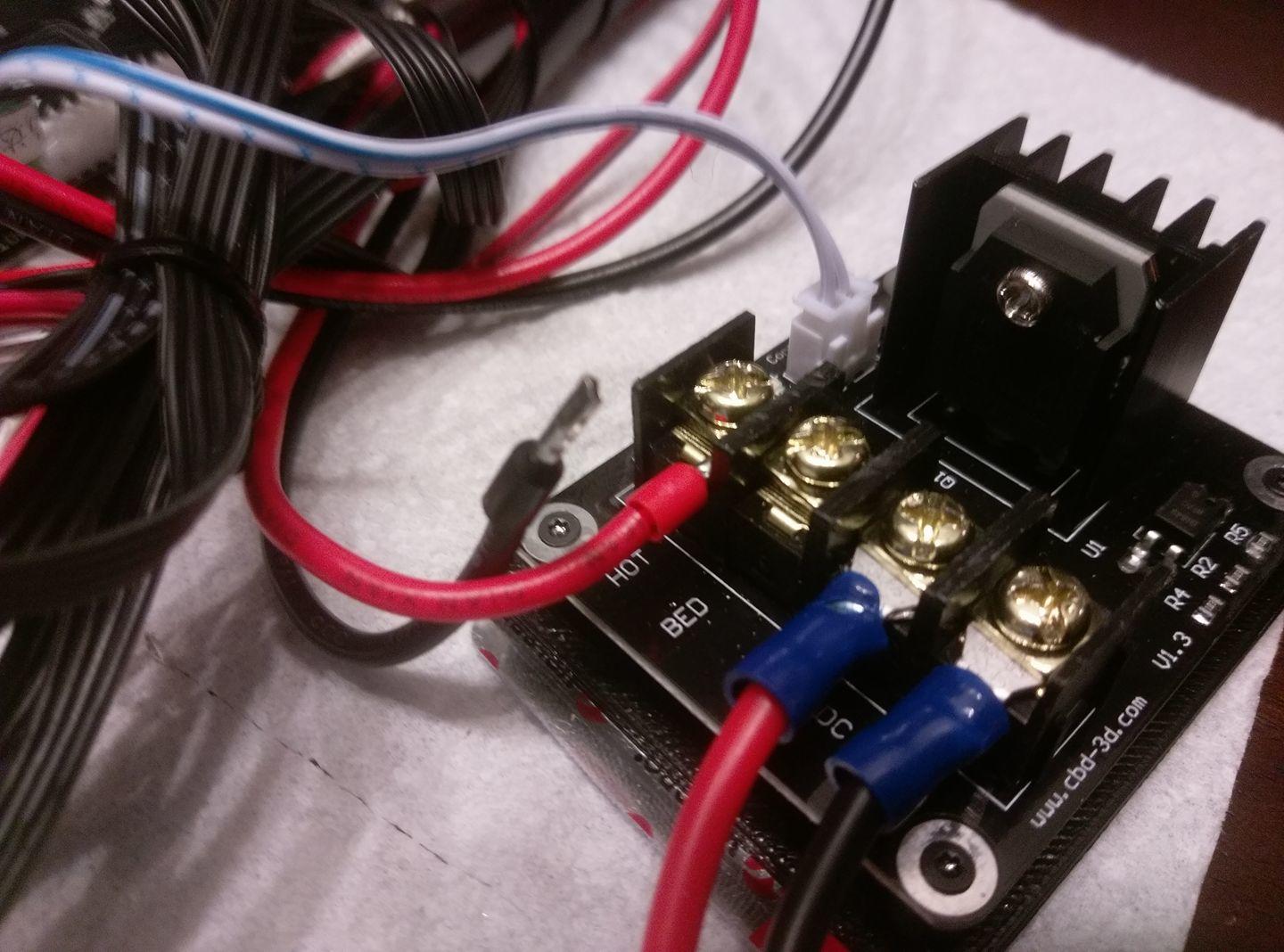 For this I use the Slicer program. It also needs to be set up correctly - specify the temperature, the size of the extruder nozzle. After that, the data can be sent to the printer.
Slicer interface
As a raw material for printing, I recommend starting with regular ABS plastic - it is quite strong, products made from it are durable, and it does not require high temperatures to work with. For comfortable printing with ABS plastic, the table must be heated to a temperature of 110-130 ° C, and the extruder nozzle - within 230-260 ° C.
Some important details. Before printing, calibrate the machine along the Z axis. The extruder nozzle should be approximately half a millimeter from the table and ride along it without distortion. For this calibration, a regular sheet of A4 paper inserted between the nozzle and the surface of the heated table is best suited. If the sheet can be moved with little effort, the calibration is correct.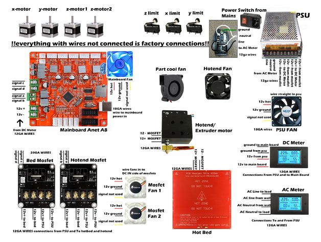
Another thing to keep in mind is the surface treatment of the heated table. Usually, before printing, the surface of the table is covered with something that hot plastic sticks to well. For ABS plastic, this can be, for example, Kapton tape. The disadvantage of adhesive tape is the need to re-glue it after several printing cycles. In addition, you will have to literally tear off the adhering part from it. All this, believe me, takes a lot of time. Therefore, if it is possible to avoid this fuss, it is better to avoid it.
An alternative option that I use instead of scotch tape is to apply several layers of ordinary light beer, followed by heating the table to 80-100 ° C until the surface is completely dry and re-applying 7-12 layers. It is necessary to apply the liquid with a cloth moistened with a drink. Among the advantages of this solution: ABS plastic separates from the table on its own when it cools down to about 50 ° C and is removed without effort, the table does not have to be peeled off, and one bottle of beer will last you for several months (if you use the drink only for technical purposes :)).
After we have collected and configured everything, we can start printing. If you have an LCD screen, then the file can be transferred for printing using a regular SD card.
The first results may have bumps and other artifacts - do not worry, this is a normal process of "grinding" the printer elements, which will end after a few print cycles.
Tips to make life easier (and sometimes save money)
In addition to the small recommendations given in the text above, in this section I will also give a short list of tips that will greatly simplify the operation of a 3D printer and the life of its owner.
- Do not experiment with nozzles. If you plan to immediately print from materials that require high temperatures, then it is better to immediately take the MK10 extruder. On MK8, you can "hang" special nozzles that support high-temperature conditions. But such modifications often cause difficulties and require special experience.
 It is better to avoid this fuss on the shore by simply installing the right extruder for you.
 - Add starter relay for heated table. Improving the power supply system for this important printing part with a starter relay will help solve the known problem of RAMP 1.4 - overheating of the transistors that control the power of the table, which can lead to failure of the board. I made this upgrade after having to throw away a few RAMPS 1.4s.
- Select the correct filament diameter for printing. I recommend using 1.75mm plastic for MK8 and MK10. If we take plastic, for example, 3 mm, then the extruder simply does not have enough strength to push it at an acceptable speed - everything will be printed much longer, and the quality will drop. ABS plastic is ideal for MK8, MK10 will be able to produce products from polycarbonate.
- Use only new and precise X and Y guides. Print quality will be affected. It is difficult to count on good quality with bent or deformed guides along the axes.
- Take care of cooling. During my experiments with various extruders, the MK10 showed the best results - it prints quite accurately and quickly. The MK10 can also print plastics that require a higher print temperature than ABS, such as polycarbonate. Although it is not as prone to overheating as its younger brother MK8, I still recommend taking care of its cooling by adding a cooler to your design. It must be permanently enabled, this option can be configured in Slicer. You can also add coolers to keep the stepper motors at an acceptable temperature, however, make sure that their air flows do not fall on the printed part, as this can lead to its deformation due to too rapid cooling.
- Consider heat retention. Yes, on the one hand, we are struggling with overheating of the elements. On the other hand, a uniform temperature around the printer will contribute to high-quality printing (the plastic will be more pliable). To achieve a uniform temperature, you can put our printer, for example, in a cardboard box.
 The main thing is to connect and configure the coolers before that, as described above.
 - Consider insulating your desk. Heated table heats up to high temperatures. And if part of this heat leaves properly, heating the printed part, then the second part (from below) just goes down. To concentrate the heat from the table onto the part, you can perform an operation to insulate it. To do this, I simply attach a cork mouse pad to its bottom using stationery clips.
Pins
I am sure that during the assembly process you will encounter a number of difficulties specific to your project. Neither this text nor even the most detailed guides will insure against this.
As I wrote in the introductory part, the above does not claim the status of a detailed assembly manual. It is almost impossible to describe all the stages and their subtleties within the framework of one such text. First of all, this is an overview material that will help you prepare for the assembly process (both mentally and financially), understand whether you personally need to bother with self-assembly - or give up on everything and buy a ready-made solution.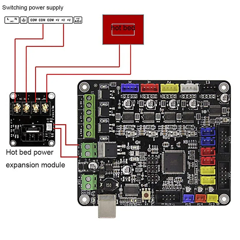
For me, assembling printers has become an exciting hobby that helps me solve some issues in home and work affairs, take my mind off programming and do something interesting with my own hands. For my children - entertainment and the opportunity to get unusual and unique toys. By the way, if you have children whose age allows them to mess around with such things, such an activity can be a good help for entering the world of mechanics and technology.
For everyone, the vectors of using 3D printers will be very different and very individual. But, if you decide to devote your personal time to such a hobby, believe me, you will definitely find something to print :)
I will be glad to answer comments, remarks and questions.
What to read/see
- what can be printed;
- 3D printer forum;
- RepRap community site with model descriptions and assembly instructions;
- printer that prints electronics.
Everything about Ukrainian IT in Telegram — subscribe to the editorial channel DOU
Topics: DIY, embedded, tech
Welcome to NIOZ.
 RU
RU Sort by
Product Name +/-
Product Price
Featured Products
Product Availability
Showing 1 - 60 of 662
153060150
Products
3D Scanner Ciclop
RUB 8500.00
Notify me when available
Product description
400 ml
RUB 1940.00
Product description
RUB 390.00
Product description
350 ml
RUB 850.00
Product description
Ready to print
RUB 23700.00
Item description
Ready to print out of the box
RUB 14500.00
Notify me when available
Product description
Print ready
RUB 19900.00
Product description
Print ready
RUB 20900.00
Notify me when available
Product description
Ready to print
RUB 23900.00
Item description
Ready to print out of the box
RUB 43500.00
Item description
Print ready
RUB 39000.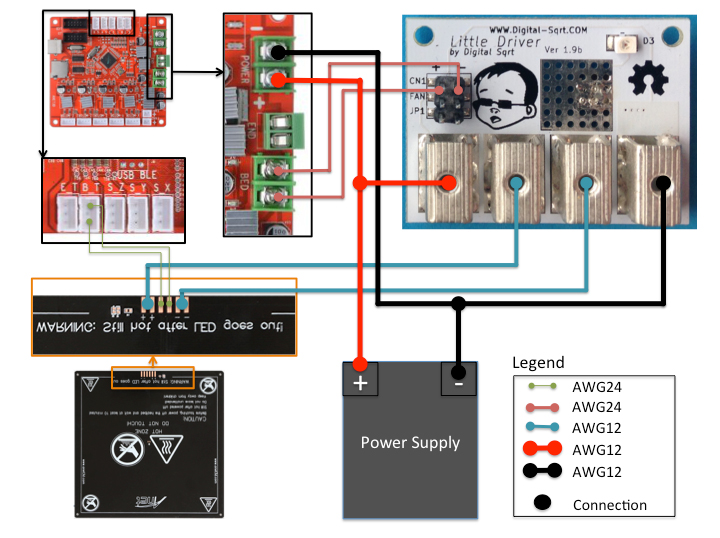 00
00
Product description
LCD 0.7/1.75 mm
RUB 1550.00
Notify me when available
Product description
OLED, 0.6/1.75mm, USB
RUB 2150.00
Notify me when available
Product description
RUB 650.00
Product description
Wiznet W5100 Arduino Shield
RUB 650.00
Notify when available
Product description
RUB 550.00
Product description
Assembly kit
RUB 2500.00
Notify me when available
Product description
Volume: 1 l.
RUB 3100.00
Product description
Boscam 200mW, 5.8GHz
RUB 4550.00
Product description
Chimera, e3d
RUB 1700.00
Product description
Print head 1.75mm 0.4mm
RUB 1100.00
Product description
Double printhead 1.75mm 0.4mm
2500.00 RUB
Notify me when available
Product description
Long
RUB 750.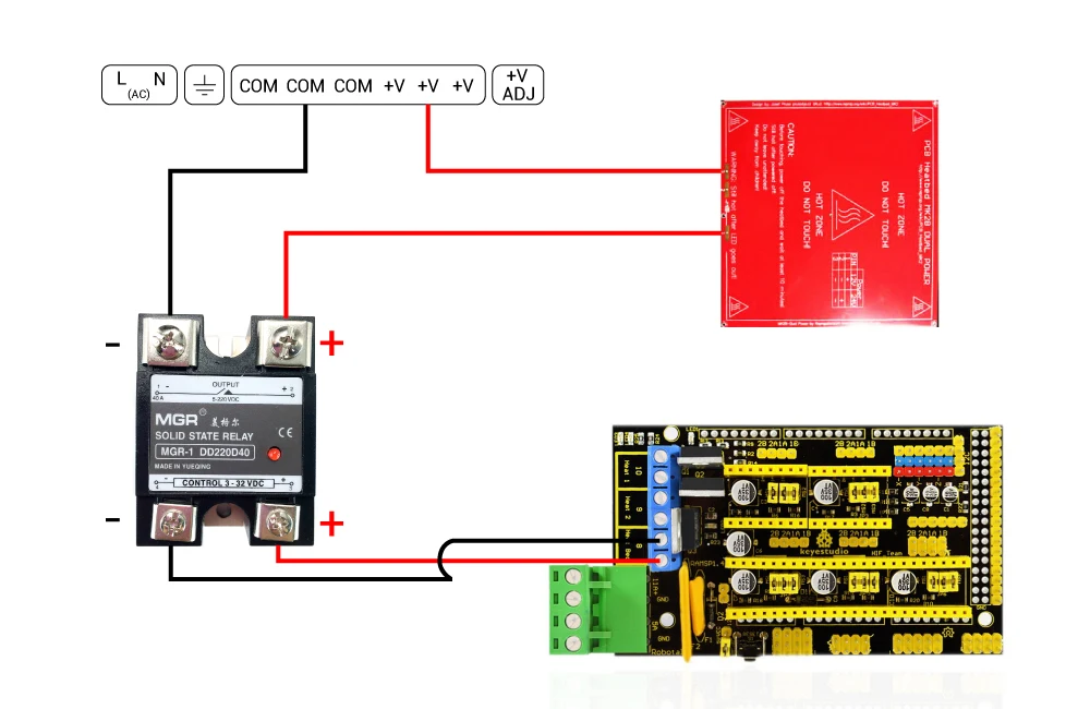 00
00
Product description
Short
RUB 700.00
Item description
RUB 100.00
Notify me when available
Product description
LERDGE 2IN1
Call for Quote
Notify me when available
Product description
Call for a quote
Notify me when available
Product description
Quantity: 1 set Weight: 10 g
RUB 100.00
RUB 1900.00
Notify me when available
Product description
APM2.6 mavlink
RUB 1350.00
Product description
ESP8266 is a highly integrated chip
RUB 250.00
Product description
Call for a quote
Notify me when available
Product description
11.1V, 20C
RUB 1900.00
Item description
11.1V, 25C
RUB 1250.00
Notify me when available
Product description
11.1V, 25C
RUB 2100.00
Product description
Heat block v6
RUB 150.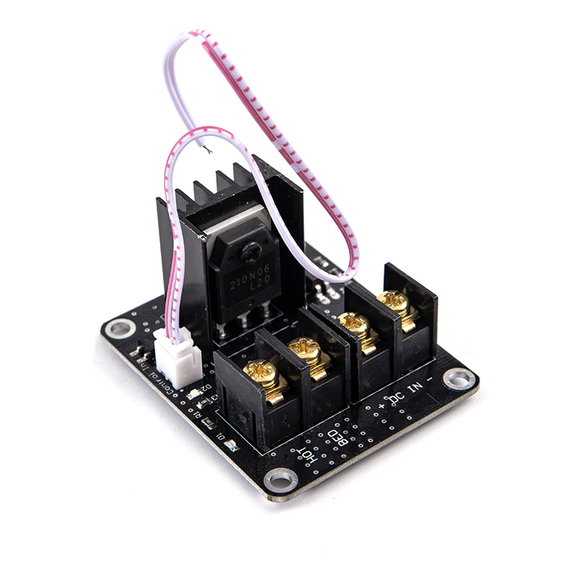 00
00
Item description
cartridge type thermistor
Heat block Volcano
Output parameters: 24 V, 600 W.
RUB 3300.00
Product description
12V 20A
RUB 1550.00
Product description
12V 30A
RUB 1950.00
Notify me when available
Product description
12V 5A
RUB 450.00
Notify me when available
Product description
24V 15A
RUB 2100.00
Report Admission
Product description
RUB 250.00
Product description
Hobbed bolt
RUB 150.00
Item description
Price per 10mm (free cutting)
RUB 13.00
Product Description
Price per 10mm (free cutting)
RUB 17.00
Product Description
Section 400mm
RUB 650.00
Product description
Price per 10mm (free cutting)
RUB 25.00
Product description
10mm (cut to size)
RUB 70.