3D printer frame design
Workhorse Printer - 3D Distributed
Home
3D Printers
Workhorse Printer
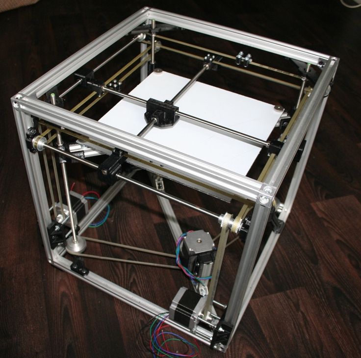
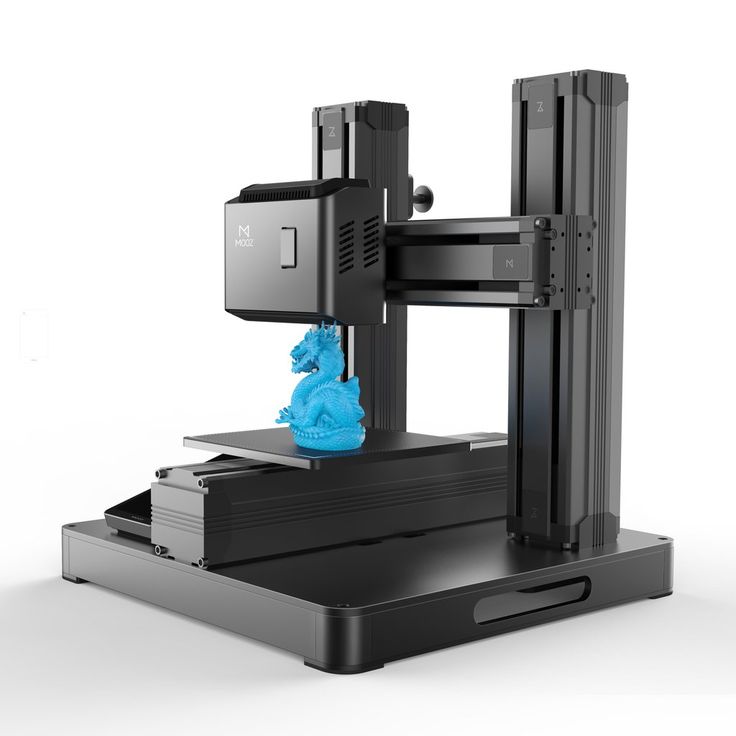
Workhorse 3D PrinterWorkhorse- Large DIY Industrial 3D Printer Platform
Build Volume – 650 x 350 x 350 mm
DIY 3D Printer Build – Large 3D Printer Kit
Motion System – XYZ Lead Screw / Ball Screw
Machine Kinematics – Fixed Bed / Moving Gantry
Enclosure – Polycarbonate Enclosed
Extruder – Bowden / Direct Drive Extruder
Materials – Filament – FDM / FFF
Controller – Duet3D
Operating System – RepRap Firmware
Design – Open Source
Software– Simplify3D / SuperSlicer
Skill Level – Advanced
Lead Screw vs Belts
The WorkHorse is a large customizable 3d printer platform for designers, builders, and makers. The XYZ Lead Screw motion system is an open-source design that can be adapted to specific materials and applications. In most cases, belt driven 3d printers are better suited compared to lead screw. But this isn’t most cases and the lead screw we selected to drive the WorkHorse isn’t your standard lead screw. We’ve tried a range of different styles of lead screw and had mixed results. We settled with a Igus high helix thread pitch with a 50mm lead.
If you’re looking for an advanced project like building a large 3d printer, the WorkHorse is an open-source design that you can customize for a specific application or project.
Large DIY 3D Printer BuildLead Screw / Ball Screw Motion System
WorkHorse PrinterWorkHorse Build Resources
- WorkHorse BOM
- WorkHorse Documentation
The fixed bed / moving gantry is intended to make the 3d printer more scalable as the bed and z-axis mechanism becomes heavier.
- Fixed Bed / Moving Gantry
- X and Y-Axis Lead Screw
While most 3d printers use belt driven motion in the x and y axis to increase print speed but loses quality when more weight is applied to the gantry or carriage.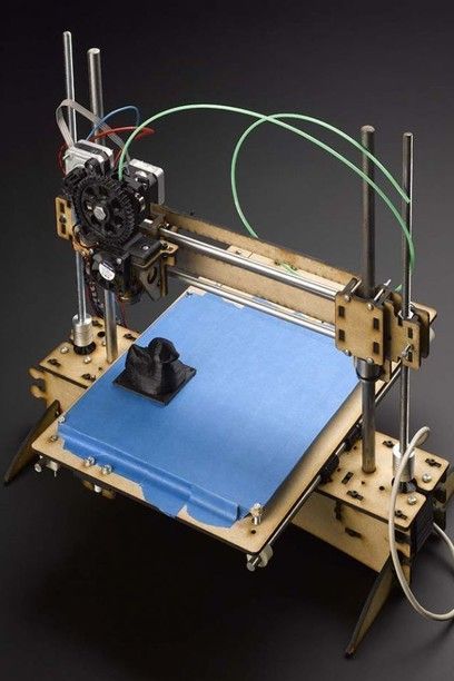 The lead screw used on the Workhorse has a high helix pitch with multiple threads to allow increased print speeds while maintaining the quality provided from lead screw and ball screw motion. The system is particularly useful in applications that add more weight to the gantry or carriage. Materials such as clay, chocolate, plastic pellet extrusion or other foods can increase weight that is moved around which results decreased quality or print speeds. Workhorse Printer’s are available to purchase in Machined Component Kit, Hardware Kit or Complete Kit.
- OPEN SOURCE
- LARGE BUILD VOLUME
- ADVANCED LEAD SCREW MOTION
- MODULAR MACHINE DESIGN
- CUSTOM MODS
- CUSTOM BUILDS
- ENCLOSURE
- HEATED BED
Carriage
Workhorse DIY 3D Printer Carriage DesignLarge 3D Printer KitFrameWorkhorse Printer Frame and Gantry OnlyWe’re experimenting with changing the frame size and switching to a 3030 extrusion profile.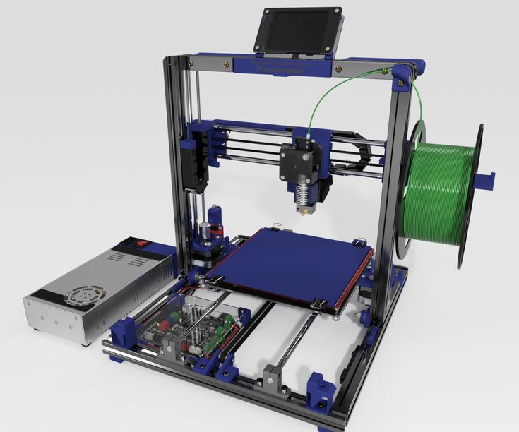 We also made the side panels two inches wider to have more room in the electronics / Filament compartment.
Z-Axis Updates
WorkHorse 3D Printer V2 Gantry Plate Z axis lead screwWe finally made a better z-axis lead screw mount.
Z-Axis Lead Screw To Gantry Plate MountDownload 3D Model
workhorse large 3d printer build 3d printed lead screw nut mountsThe old version of the lead screw nut mounts were 3d printed. They would crack over time so the version is now made from aluminum.
Custom 3D Printer PartsThe Workhorse X-Carriage design is a heavy duty solution for lead screw driven motion that uses MGN12H linear rails and 20×40 or 20×20 aluminum extrusions.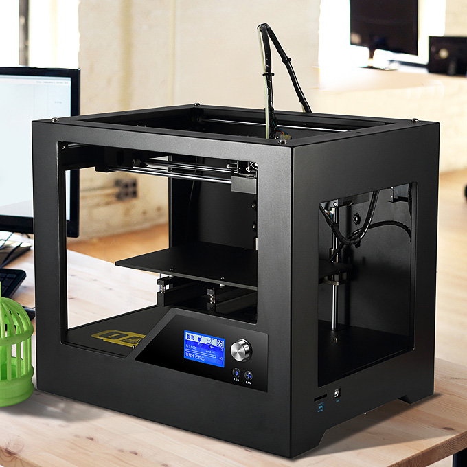
Y-Axis Motor Mount
Y-Axis Motor Mount to X-Carriage WorkHorse CarriageThe Workhorse 3d printer is available with custom mods and upgrades. We’ve several custom designed machines for many of our customers. If there is a specific size or requirement you just give us a shout.
New Heated BedWorkHorse Printer UpdatesDownload Files
WorkHorse Printer CADBOM| Lead Screw | Description | Part Number |
X-Axis 2pcs.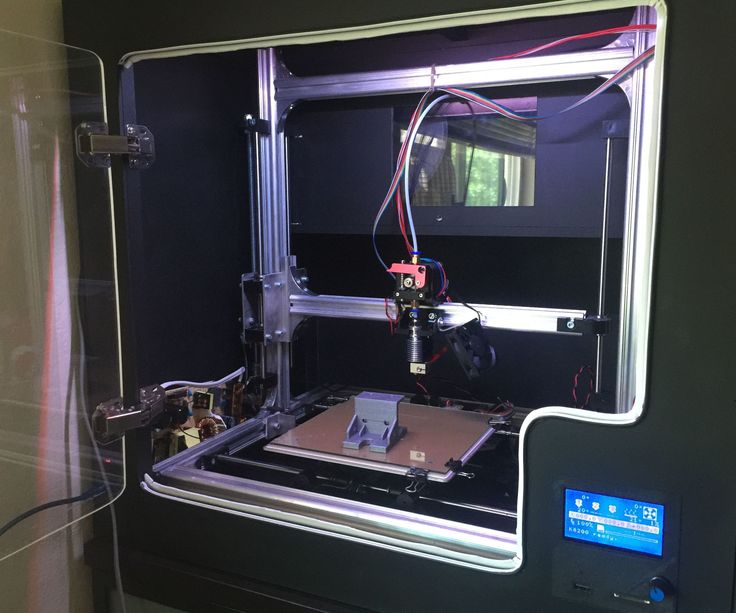 x 762mm Long x 762mm Long | Igus High Helix 10mm w/50mm Lead | DST-LS-10×50-R |
| Y-Axis 1pc. x 485mm Long | Igus High Helix 10mm w/50mm Lead | DST-LS-10×50-R |
| XY-Axis 3pcs x Lead Screw Nuts | Igus Lead Screw Nuts | DST-JFRM009 |
| Z-Axis 2pcs x T12x2 Trapezoidal ACME Lead Screw w/ Brass Nut | 500mm Long | WK-Z-T12500 |
| Linear Rails | Discription | Discription |
| 1pc. x 450mm Long | MGN12H 20mm x 20mm Hole Pattern | WK-Y-LRMGN12h500 |
| 2pcs. x 700mm Long | MGN12H 20mm x 20mm Hole Pattern | WK-Y-LRMGN12h500 |
| 4pcs. x 500mm Long w/ Two Carriage Blocks | MGN12H 20mm x 20mm Hole Pattern | WK-Y-LRMGN12h500 |
Buy WorkHorse 3D Printer Parts
WorkHorse 3D Printer PartsWorkHorse 3D Printer Gantry Plates| Machined Hardware | Price $ | Source |
| Gantry Plates | 3DDistributed | |
| X- Axis C- Carriages 2pcs | 3DDistributed | |
| Y-Axis C- Carriage 1pc | 3DDistributed | |
| Y-Axis Motor Mount 1pc | 3DDistributed | |
| Y-Axis Idler Mount 1pc | 3DDistributed | |
| Hotend Mount | 3DDistributed | |
| Z-Axis Motor Mounts 2pcs | 3DDistributed | |
| Aluminum Build Plate | $135. 00 00 | 3DDistributed |
Electronics
Buy Stepper Motors
See Stepper Motors
Z-Axis Motor Mounts
Z-Axis Motor MountsWorkHorse Printer V2
Workhorse Z-Axis Motor AssemblyDuet3D Firmware Files
Download
We now recommend the Duet 3 Mainboard 6HC electronics by Duet3D.
Build Instructions
Here
Sourcing Parts For Your Workhorse 3D Printer
Sourcing Lead Screw
Sourcing Frame Components
Buying Frame PartsFrame Assembly
Workhorse Frame ExtrusionsThe frame is made out of 2020 (20mm x 20mm) aluminum extrusions.
- 20mm x 20mm
- 4pcs 930mm Long
- 6pcs 510mm Long
- 10pcs 570mm Long
- 3pcs 808mm Long
.
20mm x 40mm HFS5 Aluminum Extrusions (Misumi Brand)
4pcs 510mm Long
Frame:
BOMFrame BOM Part List
| Frame Extrusions | Length | Units | Discription | Misumi Part # |
| 2020 (20mm x 20mm) | 930mm Long | 4pcs | Horizontals | HFS5-2020-930 |
| 2020 (20mm x 20mm) | 510mm Long | 6pcs | Verticals | HFS5-2020-510 |
| 2020 (20mm x 20mm) | 570mm Long | 10pcs | Frame Width | HFS5-2020-570 |
| 2020 (20mm x 20mm) | 808mm Long | 3pcs | Bed Support | HFS5-2020-808 |
| Gantry Extrusions | Length | Units | Description | Part# |
| 2040 (20mm x 40mm) | 770.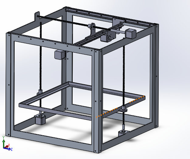 5mm Long 5mm Long | 2pcs | Gantry Horizontals | HFS5-2040-770 |
| 2040 (20mm x 40mm) | 456mm Long | |||
| 2040 (20mm x 40mm) | 510mm Long | 4pcs. | Z axis Linear Rail Verticals | HFS5-2040-510 |
| Frame Components | Type | Units | Description | Part# |
| Frame Brackets | 20mm Wide | 90pcs | Reversal Tabbed Brackets | HBLFSNF5 |
| T-Nuts (Misumi) | M4 | 75pcs | M4 | HNKK5-4 |
| T-Nuts (Misumi) | M5 | 180pcs | M5 | HNKK5-5 |
| T-Nuts (Misumi) | M3 | 75pcs | M3 | HNKK5-3 |
| Frame Price | Price $ | |||
| Profile Extrusions | $ 122.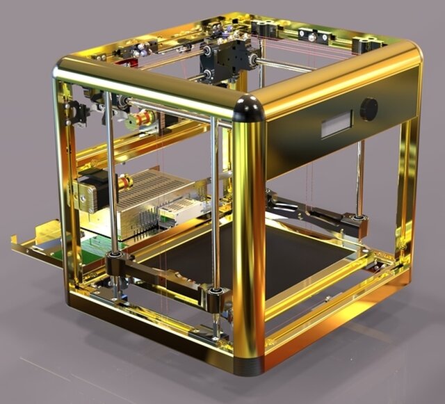 29 29 | extrusions and brackets w/tax and shipping | ||
| M5 x 10 Cap Screws (200pcs) | $ 9.99 | 225$ | ||
| brackets | $ 40.32 | |||
| T-nuts | $ 19.32 | |||
| Total | $ 191.92 |
Frame Assembly
Workhorse Frame Step 1Workhorse Frame Assembly DiagramFrame Diagram Front ViewFrame Diagram Front ViewGantry
Gantry Motor PlatesAssembling The Gantry PlatesPart List:
- 1pc. x Gantry Motor Plate
- 1pc. x Gantry Idler Plate
- 16pcs. x M5 x 14mm Long Screws
Gantry Plates Before Gantry Frame And Motor
Gantry Plates Assembled To FrameView this post on Instagram
A post shared by 3D Distributed (@3d_distributed)
X-Carriage
X-CarriageX and Y-Carriages use 4 M3x6mm Screws
- X-Carriage (X-Axis) 2pcs
- Y-Carriage (Y-Axis) 1pc
- M3x6mm Screws 12pcs (4 for each Carriage)
The x-axis carriage screws down to the 2040 Y-axis extrusion and rail. *Note* The y-axis 2040 extrusion must have hand tapped M5 threaded holes.
Y-Axis AssemblyLinear Rails
The Workhorse Printer uses MGN12H linear rails with a 20mm x 20mm Hole Pattern.
BOM:
- 500mm Long Z Axis (4pc)
- 700mm Long X Axis (2pc)
- 450mm Long w Y axis (1pc)
Linear Rail Screw:
- M3x9mm Long Screws 26 per X-Axis
- M3x9mm Long Screws 14 for Y-Axis
- M3x9mm Long Screws 18 per Z–Axis
Total M3x9mm screws 138pcs.![]()
Motor Mount to Carriage
- M3x8mm Long Screws 4pcs
Igus dryspin lead screw nuts do not require lubrication. This is normal for Igus materials. If you have any sounds, vibrations or wear, then the problem is most likely in the alignment and assembly of the mechanical components.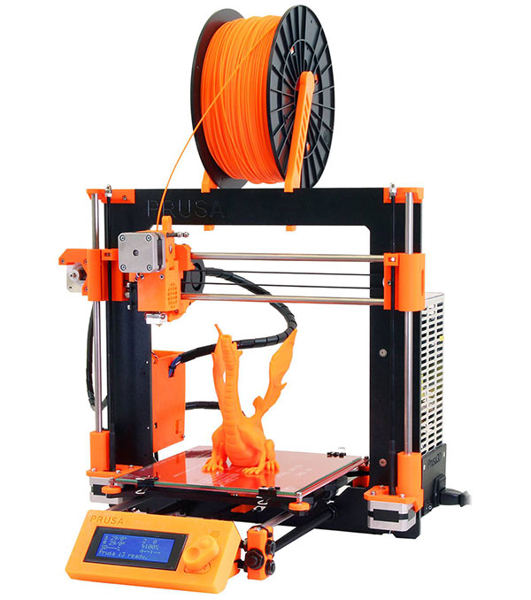
X-Carriage Lead Screw Nut Insert 2pcs
- Each Insert uses:
- M3x35mm screws 4pcs
- M5x55mm Long
Electronics
Stepper Motors
Heated Bed
View this post on Instagram
A post shared by 3D Distributed (@3d_distributed)
Like this:
Like Loading...
Build a 3D printer - Part 1: Inventory
Reprap is a very popular Open Source 3D printer. The idea of this project is of a self replicating machine that can create copies of itself. So when you want to build your own 3D printer, the first thing is to get a set of 3D printed parts. It is a good idea to dive into the RepRap community and get to know people that can help you acquire them. You have the option to buy a complete DIY 3D printer set that includes all the parts, but this is of course less fun than assembling everything yourself.
I have chosen a slightly different approach as I did not know anybody with a 3D printer and I had no idea which printed parts I needed. I decided to buy a cheap 3D printer from China and use it as base for building my own 3D printer. After getting acquainted with the 3D printer I was ready to start my own project. My goal was to build a Reprap Prusa i3 model, as I read a lot of good things about it and it was widely used among hobbyist. I also wanted to be able to print in 2 colors, so the printed needed to have a dual extrusion system.
The first think that you will need is a frame. It is the base of your printer and it will greatly determine the quality of your prints. The 3D printed parts ensure that you can combine other parts needed for the frame. The exact version of my printer is called: Reprap Prusa i3 Rework. However I have modified it a bit, mainly for stability and ease of setup.
I have started to look for the parts and a good manual about the printer with a complete BOM (Bill Of Materials). After some research I have found several resources that were very helpful.
- Reprap website. This will give you a good idea about which printed parts are needed
- Thingieverse project which has a list of the 3D files to print (in STL format)
- Manual on how to assemble the frame
- Howto guides from the official Prusa website
I understand that it is a lot of information to swallow, so I will try to split it up into small pieces that are clear to understand.
Next to the printed parts, to build the main frame structure you will also need the materials listed below. The second part of the frame will include the rods for the Z and X-axis and I will cover it in the next parts of this tutorial.
The frame itself is a cutout of 6 mm aluminum plate and is based on a DXF drawing which looks like this:
Here you can download the Prusa3ALU-FREZOVANY-v4.dxf source file. It is possible to make a laser cutout when you provide this file for a company that has a machine to do it, but it is very expensive if you just order one piece. You can also buy this frame online. I have ordered mine in an online Chinese webshop for around 70 euro. You have also the option to 3D print this frame, or make a cutout from wood but I do not recommend it, as the whole stabiliy of the printer will be compromised and it will affect the quality of your 3D prints.
To form the base structure you will also need M10 (which stands for 10 millimeters in diameter) threaded rods with these lengths:
- 3x M10 x 210 mm threaded rod
- 2x M10 x 360 mm threaded rod
- 1x M10 x 370 mm threaded rod
- 2x M10 x 380 mm threaded rod
For the X,Y and Z-axes, you will need 8mm smooth steel rods (preferably chromed) in these lengths:
- 2x 370 mm - for the X-Axis
- 2x 350 mm - for the Y-Axis
- 2x 320 mm - for the Z-Axis
You will also need a total of 11 LM8UU 8mm linear ball bearings. 3 of them, we will use for the slidable printing bed platform, 4 will be used for the X-axis where the extruder will be mounted and the remaining 4 are for the Z-axes.
The remaining parts are:
- 38x M10 nuts
- 38x M10 washers
- 1x M8 x 30 mm bolt with 2x M8 washers and 1x M8 nut.
- 1x M4 x 20 mm bolt with 1x M4 nut.
- 1x 608 bearing
- Cable ties 2.5 mm wide and 100 mm long (black)
The first parts you will need to print are the Y-CORNERS. You can find them in the collection of this thingiverse project. They support the whole structure and will form the base. You will need to print 4 of them.
Next you will need to print the Y-BELT-HOLDER, Y-IDLER and Y-MOTOR. These parts are needed to hold the belt and the Y-stepper motor in place.
And the last prints for this part of the project are Z-Axis support brackets which can be found in this project by Tech3C. Print 2x z-axis-support-bottom and 2x z-axis-support-top of the 10 mm version as we will be using M10 threaded rods.
In the next part we will assemble the base of the frame.
Category
Decathlon builds a 3D-printed bike using Autodesk's generative design technologies
News
project of a bicycle with an aluminum frame customized for individual users using 3D printing.
The generative design capabilities of Autodesk Fusion 360 have helped Decathlon design, manufacture and deliver prototype components that combine quality and sustainability. Decathlon expects to reduce the amount of resources and transportation required to manufacture and sell a futuristic race bike. To do this, Decathlon plans to move to aluminum 3D printing and move away from carbon fiber, a hard-to-recycle but popular material commonly used in racing bikes.
Decathlon's drive for innovation is driven in large part by sustainability. The company's plan is to reduce the carbon footprint of the billions of items of sports equipment produced by the chain each year. To achieve this goal, Decathlon is rethinking the way it designs its products.
The project is based on Autodesk's generative design technology, a form of artificial intelligence that provides design engineers with hundreds, even thousands, of potential solutions to a design problem in minutes. The technology is powered by Fusion 360 software and uses machine learning and computational geometry algorithms and technologies to quickly create multiple solutions that meet given requirements and constraints. Optimized solutions are presented to the designer for review and subsequent improvements.
In this case, generative design was used to design the frame and fork of a bicycle. The design took into account the significant dynamic forces acting on the fork at high speeds and during braking, aerodynamics and many other factors. Decathlon predicts that rethinking the traditional design process could significantly reduce bike weight by using fewer materials.
“Autodesk technology has been instrumental in redefining the possibilities and expanding the range of options that Decathlon's engineers and designers considered when creating the bike. The bicycle project is a great example of how generative design can contribute to the creative process of designers. Our toolkit has helped Decathlon bring AI and human creativity together to achieve sustainability goals and deliver performance that meets the high expectations of consumers,” said Scott Reese, Senior Vice President of Autodesk.
Do you have interesting news? Share your developments with us, and we will tell the whole world about them! We are waiting for your ideas at [email protected]
Subscribe to the author
Subscribe
Don't want
9
Subscribe to the author
Subscribe
Don’t want
The leaders of the Rosatom business accelerator InnoHub and OOO Invoshchenie signed an agreement on the provision of...
Read more
7
Subscribe to the author
Subscribe
Don't want to
One of the key technological challenges of our time is the need for a multiple reduction in time.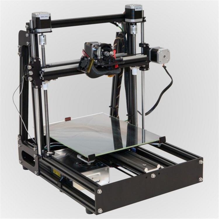 ..
..
Read more
59
Subscribe to the author
Subscribe
Don't want
The 3Dtoday portal, supported by Creality and Bestfilament, invites everyone to participate in...
Read more
Santa Cruz Bicycles uses the 450mc 3D printer to design and manufacture bicycles
Create custom
For Santa Cruz Bicycles (hereinafter referred to as Santa Cruz), a bicycle is much more than than just a way to get from one place to another. Santa Cruz bikes are the epitome of the company's mission: to create the world's most reliable, top-performing, high-performing mountain bikes that can propel their owners over rough terrain (and to new vistas). What makes this concept real? Nothing but the spirit of innovation that dominates the company.
A good illustration of this is the case of Danny MacAskill. Danny, an avid mountain biker and professional bike tester, asked Santa Cruz to build a custom bike for him.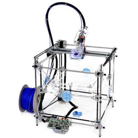 Danny chose this company because of their reputation: many Santa Cruz bikes are based on a carbon fiber frame, which makes them both strong and light. Such rigid frames and other components (no less strong) allow cyclists to conquer landscapes that were traditionally considered passable only for mountain goats. Many professional bikers and enthusiasts love Santa Cruz bikes for their quality and reputation.
The dilemma for the company in the case of a custom order was that this time it needed a "one-off", a unique design created specifically for Danny's requests. Usually Santa Cruz bikes are mass-produced in Asia, but now it was necessary to develop and produce a new carbon fiber frame "at home", in-house, and on a tight schedule.
“Designing the bike for Danny was really terra incognita for us,” says Geoff Casey, design director of the company. And development manager, Nic McCrae, adds: "What we've been trying to achieve is something that meets all of Danny's specifications exactly, is as solid as possible, and also provides us with a good base for future development and experimentation with various techniques and manufacturing techniques.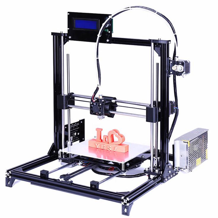 "
"
3D printing helped develop and flesh out design concepts. Printed frames gave designers the ability to visualize and refine various structural design ideas much faster. “Being able to have a real, non-abstract 3D printed frame helps us a lot, because that way we can see what we need to change without having to make special carbon tools and finalize the frame, which of course requires a huge amount of money and time ,” says Jack Russel, senior industrial designer. - It's so cool to feel this frame with your hands and see the proportions of the tubes live. You never get that feeling from a model on screen."
However, even when the design was finally approved, there was still the problem of making the bike itself using carbon fiber. And for the production of a new model of a bicycle, a completely new set of molds and tools was required. Once again, McCray and his team solved this problem with the help of 3D printing technologies. Using ULTEM™ 1010 material, the team created cores that formed the basis of mold tooling that could then be used to make a carbon fiber frame.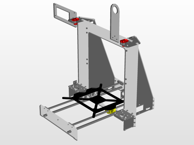
According to McCray, ULTEM 1010 opened the door to shapes that would be extremely difficult to produce with traditional methods, or that would require endless setup on a five-axis CNC machine, which would waste time and money. The use of 3D printing not only allowed Santa Cruz to cut costs, but also to meet deadlines. With the new tools, design development has become just a matter of hours, and the whole journey from a CAD drawing to a ready-to-use prototype is a matter of weeks.
Wide application
Santa Cruz collaborated with Stratasys to develop the first tools to build Danny's bike, but they soon bought their own Fortus 450mc™ 3D printer. According to McCray, it was the success with Danny's custom bike project that prompted the company to buy its own Fortus system, with the ability to use both high-impact Nylon12 and ULTEM 1010 material. Currently, 3D printing in Santa Cruz covers a huge range of tasks - from the modeling of concepts and ideas to the production of composite tooling and tools.