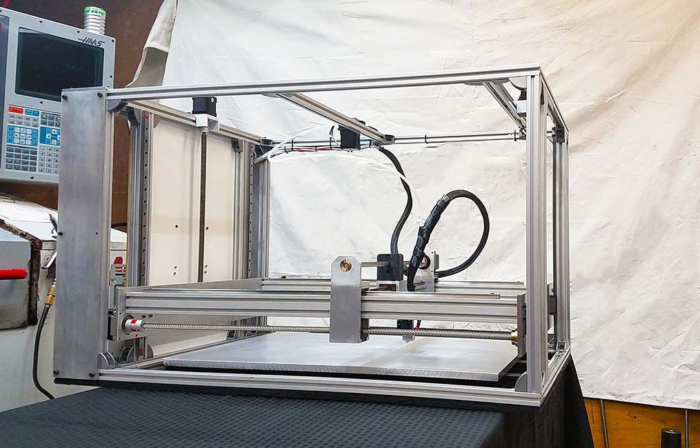
3D printer enclosure box
3D Printer Enclosures, Boxes, Cases and Covers from 3DUPfitters – 3D UP Fitters
3D Printer Enclosures
Remove dangerous plastic fumes, suppress fires, reduce noise, and manage temperature to consistently print high quality parts
Buy Now
Thousands of 3D Upfitters customers have found that our enclosures help 3D printer owners to manage temperatures and consistently manufacture high-quality parts, remove dangerous plastic fumes, reduce noise, and automatically suppress fires.
Customers include not only the top tier in the technology, transportation, and education sectors, but small schools, small businesses, libraries, and hobbyists all over the world.
We sell top quality products Made in America on using materials from American factories.
We don't make 3D printers; we make 3D printers work better.
Advanced Engineering
Heat and airflow analysis enable the best placement for vents and fansAdvanced Testing
Each enclosure is thoroughly tested in our labDual Channel 3D Printer Temperature and Air Quality Meter
Changes of season, with the thermostat ping-ponging between heat and A/C can be a challenging time to get consistent 3D prints. This dual channel temperature logger helps you track temperature changes over time to determine the optimal settings for your prints while monitoring air quality.
Product Details
I do really love this enclosure, the quality is amazing, and the results with ABS have been exactly what I was looking for! Saved me a bunch of money upgrading to a more commercial-grade printer to do what I need!
Ted M.
I wanted to send a note to you folks about how happy and impressed I am with the quality and design of your enclosure for our new Makergear M3-SE. We at Tandemloc, Inc. just purchased our first printer to manufacture some peripheral plastic components for our new automated lifter designs and the enclosure enables us to use the printer right in the engineering office, with no smell and no audible sound while printing.
William D.As a mechanical engineer I realize the amount of work that goes in to making something that works well and is simple to build. The fit and look is fantastic.
I just wanted to let you know how much I like my Prusa Mk3 enclosure. I’m not that handy but the videos and the instructions were first rate. The fit and finish of your product is really outstanding and I would highly recommend it to anyone. I was concerned about air quality. By having the enclosure venting outside, this has freed my mind to concentrate on the printing. Glorious!
James H.
I would like to commend you on the professionalism, great attention to detail, and pride each step of the way.
Chris C.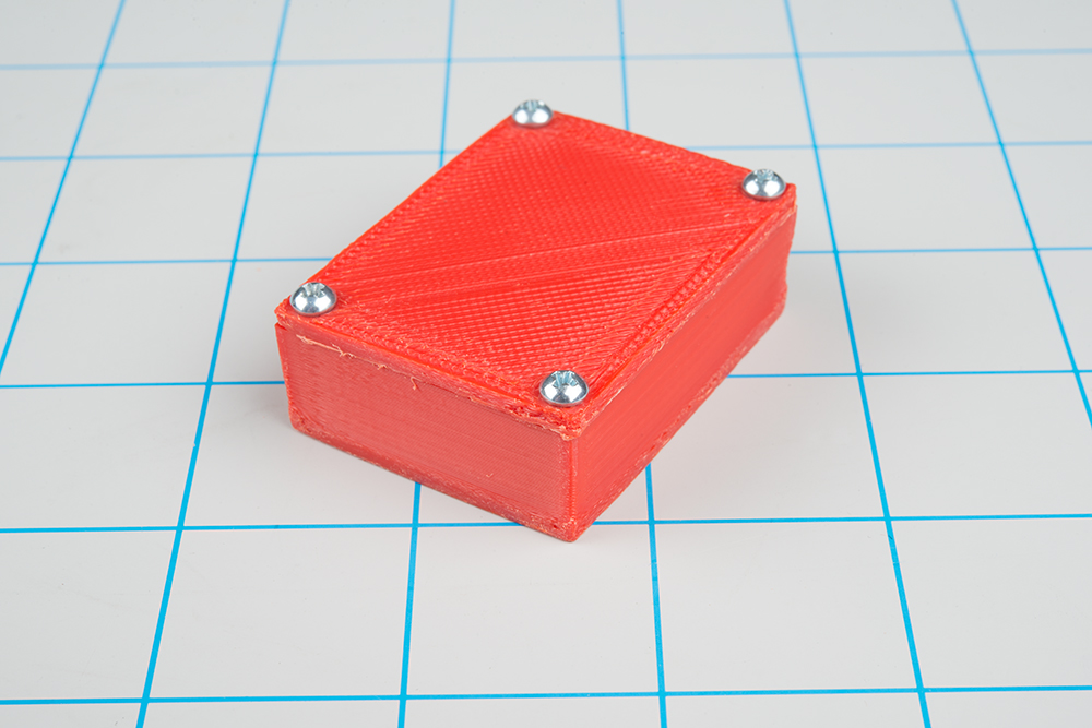
I was so pleased with the Prusa Mk3S+ and your enclosure so I went and bought another Prusa.
Jonas I.
The IKEA "Lack" table has reached legendary status among 3D printing enthusiasts. It’s amazing they can sell a table for $9 even if it is made out...
- Read more
If you've been active in the online 3D printing forums, it won't take long to come across a picture of someone's printer after a fire. But does th...
- Read more
A lot of 3D printer enthusiasts start out putting a cardboard box over the printer, but there’s a lot more to it than that! This article will expl.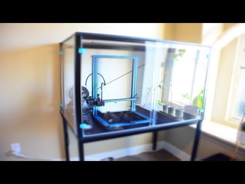 ..
..
- Read more
3D Printer Enclosures from 3DUPfitters – 3D UP Fitters
by Michael Czeiszperger
Tom M'Guinness runs the website http://carpokes.com, the "Friendly Porsche Forum", where he both provides STLs for Porsche engine fixes and ships o...
- Read more
by Michael Czeiszperger
The 3DUPfitters enclosures work by carefully aligning vents to bring cool air from outside of the enclosure to electronics and power supplies. Thi...
- Read more
by Jon Powell
The IKEA "Lack" table has reached legendary status among 3D printing enthusiasts. It’s amazing they can sell a table for $9 even if it is made out...
Sticky
- Read more
by Jon Powell
Normally we pick fan CFM to be allow of balance of heat vs air quality control.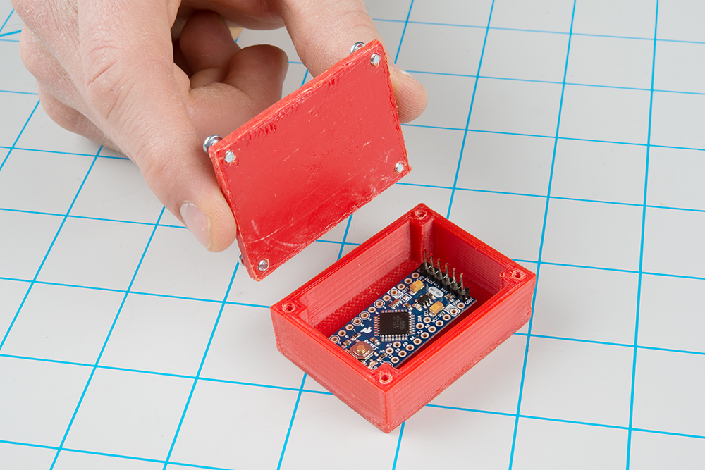 The problem is airflow that recirculates every few minutes isn’t a...
- Read more
by Jon Powell
We've got 4 Prusa MINIs running 24/7 at 3D Upfitters, and the only thing keeping them from being a perfect print farm machine was the side loading ...
- Read more
by Jon Powell
I recently tried out some cheap filament on a 1Kg spool on one of our super-smooth spool holders on a Prusa MK3S+. Since these printers are direct ...
- Read more
by Jon Powell
It's the 1950s. Leo Fender had popularized the electric guitar, which of course, required an amplifier. Like his guitars, he picked the cheapest co...
- Read more
by Jon Powell
One of the more common ideas customers have had was adding skate bearings to our acrylic spool holder, so when the supply of acrylic rods ran low, it was a no-brainer to convert the spool holder to use skate bearings instead.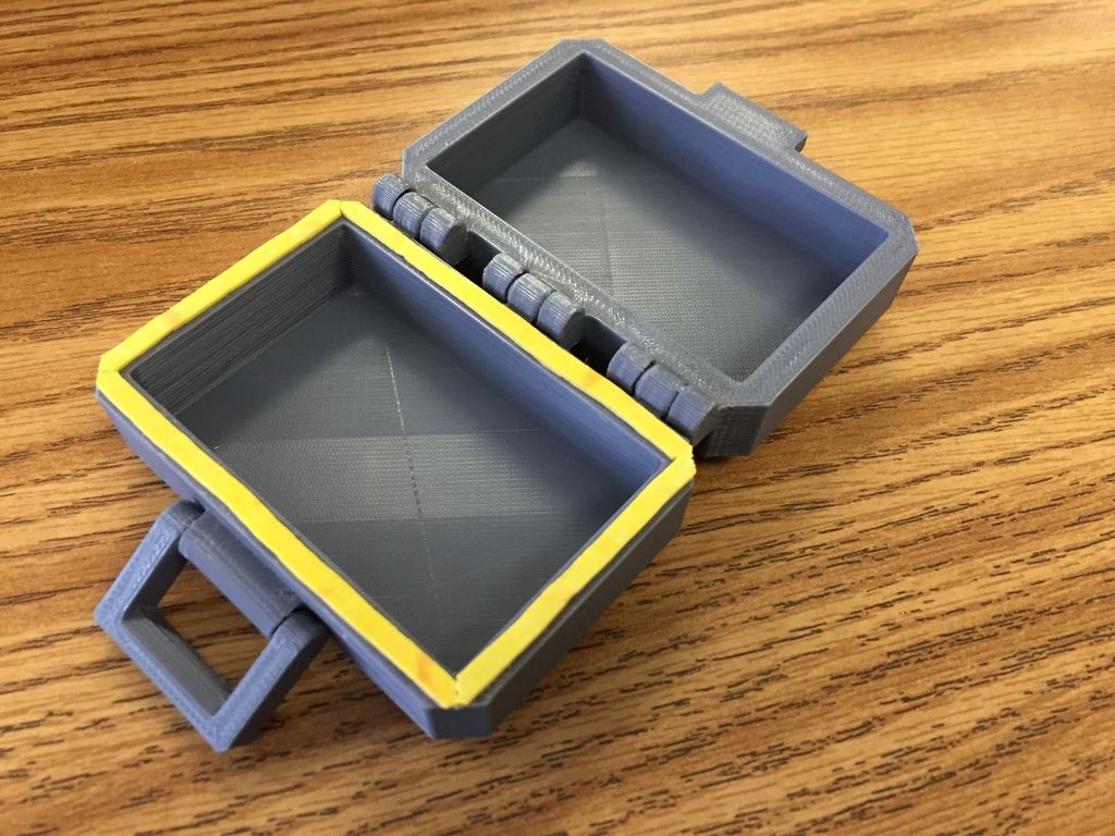 Keep in mind everything we design has to work in our print farm. The spool holders are specifically designed to require no adjustment or maintenance and just work day after day and month after month. Any changes to add skate bearings couldn't affect the practical functionality.
acrylic spool holder
- Read more
by Michael Czeiszperger
Prusa MK3 owners have it made: the rubber feet on the Prusa MK3S+ printers don't slip and they make the Prusa MK3 one of the quietest on the market...
- Read more
by Jon Powell
The grass is always greener, etc.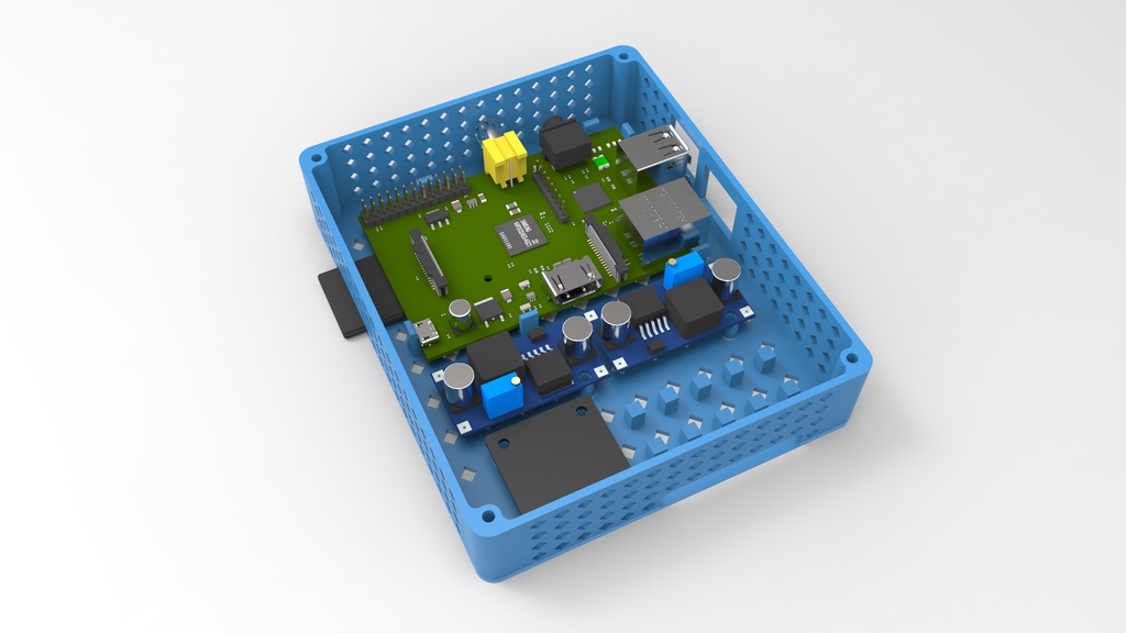 , etc. I once bought a printer with a direct drive hot end design and then read online that the smart thing to d...
- Read more
by Jon Powell
Most people don't customize their 3D printers, and thus 3D UP Fitters enclosures are designed to work with the stock configuration and as few modif...
3d printer 3D Printer Enclosure 3d printing
- Read more
by Michael Czeiszperger
If you've been active in the online 3D printing forums, it won't take long to come across a picture of someone's printer after a fire. But does th...
Sticky
- Read more
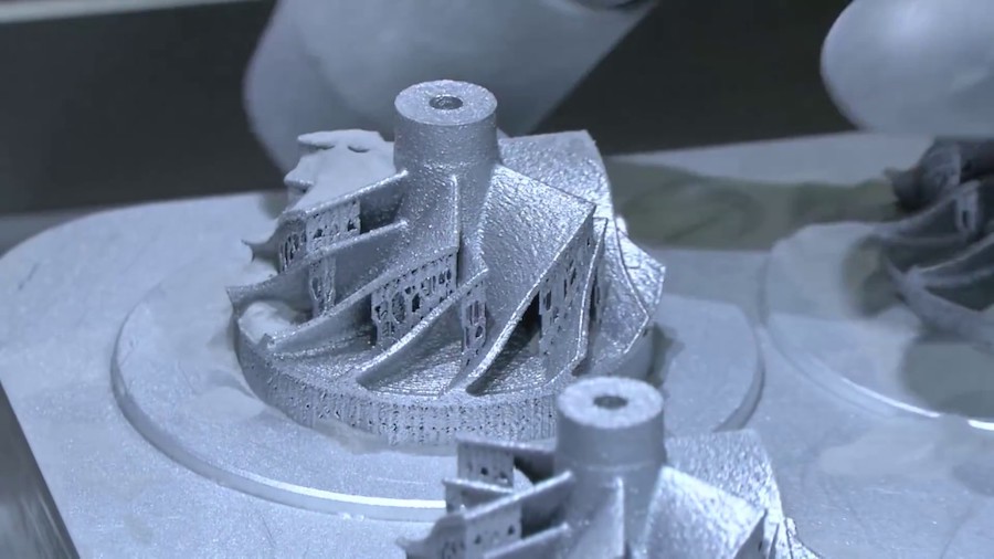
We print the simplest case for a homemade device / Sudo Null IT News
Printing a suitable case for your device is probably the most popular thought when introducing any inventor to 3D printing technology. But in practice, everything turns out to be not as simple as in an advertisement for a 3D printer, and under the cut, I will tell you in more detail what conclusions I came to in trying to compose a convenient case design.
Everything is fine with 3D printing - it's just a magic wand for the craftsman, except that most will only be able to afford models of printers in the lower price range. And after taking possession of a 3D printer, most, like me, will face the imperfection of budget 3D printing technology, namely FDM technology (layer-by-layer deposition - uses most of the available printers), regardless of whether you assembled the printer yourself or bought it in a store.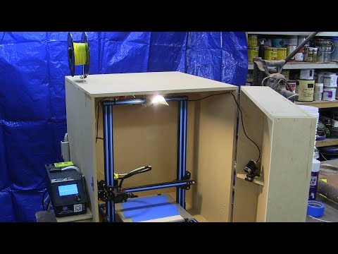 The main problems are the shrinkage of the material after cooling, which causes deformations and inaccurate linear dimensions of the printed parts. If you came up with some cool design in the likeness of mass-produced cases, then the case of your device will be generously saturated with neat bevels, holes or snaps exactly in size for ease of assembly ... even being a professional in modeling and taking into account the problems listed above when printing, you will get tired of mixing all these sizes and think in what position it is better to print each detail so that nothing bends during shrinkage, as is often the case. Shrinkage is evil, especially frustrating and time-consuming when your design has many dimensions that need to be accurately maintained for assembly and a beautiful look. But not everything is so bad and this is not a reason to retreat).
Based on my printing experience, I came up with a simple design for a prototype device box that will be easy to print on any fdm printer and suitable for many projects.
The design consists of two parts: the chassis - on which we will mount the parts, and the casing itself - which will hide all the shame that we soldered) One is easily inserted into the other and, for reliability, is fixed with a single screw at the back of the case.
The chassis is printed in a horizontal position to easily accommodate horizontal component mounting locations. Then I just glue them in the corners with droplets of hot glue, it's faster and easier to disassemble them later if necessary.
Chassis I recommend to generously pierce the bottom and sides to save material, less deformation during shrinkage and easier peeling off the table. I just extrude circles, do you remember what bubbling is?)
And I print the casing vertically. In this position, you can make thin even walls and the texture on almost the entire visible part of the body is obtained in one direction, it looks neat. If necessary, you can finish the mounting ears or legs.
Even if you can't exactly maintain the size the first time and you have to grind off the edges of the chassis a little with a file, there will be absolutely no traces of processing from the outside of the device.
The tapered feet on the bottom of the body are printed without supports, eliminating post-processing and saving material/time.
If you print on adhesive tape or glue, the surface that sticks to the table is usually uneven and needs to be processed. With this approach, it will be on the back side of the case (on the side of the interface connectors), which no one usually sees.
I printed this case from PLA plastic with a 0.3mm nozzle on a Russian-made MZ3D-256 printer with the following structure settings: wall thickness 0.6mm, infill 23%, without substrate printing.
The size of the case in my example allows you to place inside an arduino uno, a pair of relays, a stepper motor driver, a voltage converter, various communication connectors and control / indication elements.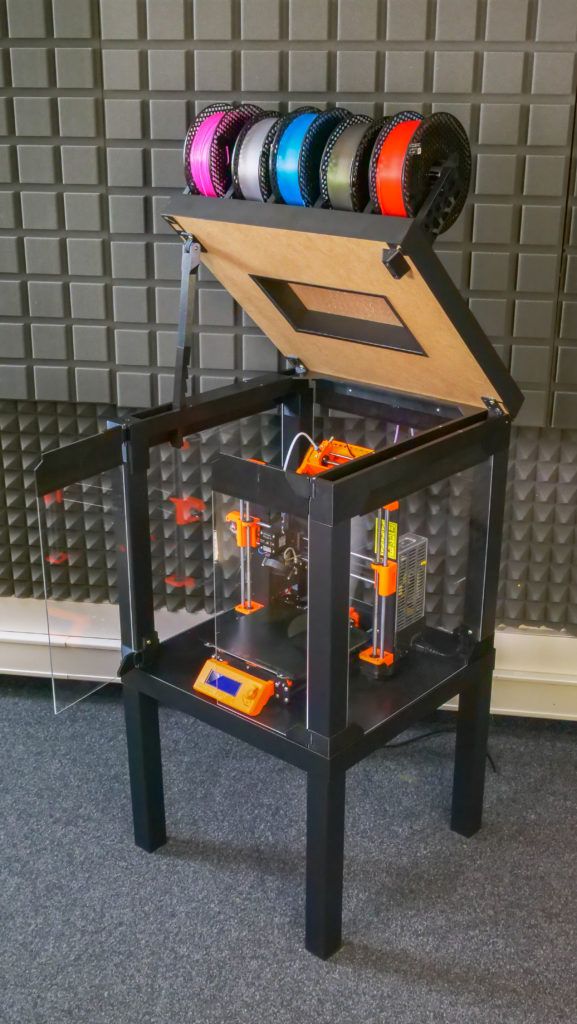
Of course, you will draw the chassis of the required size for your modules, as long as the printer's printable area is enough to print the casing in one piece. In my opinion, this design will be the most simple and convenient.
The benefit from the case is obvious) The design does not fall apart, wires do not stick out of the device, it does not look like a bomb, no one knows that it works on an arduino and it is not a shame to show it at an exhibition or give it to programmers to write firmware.
I hope this information was useful to someone, thank you for your attention.
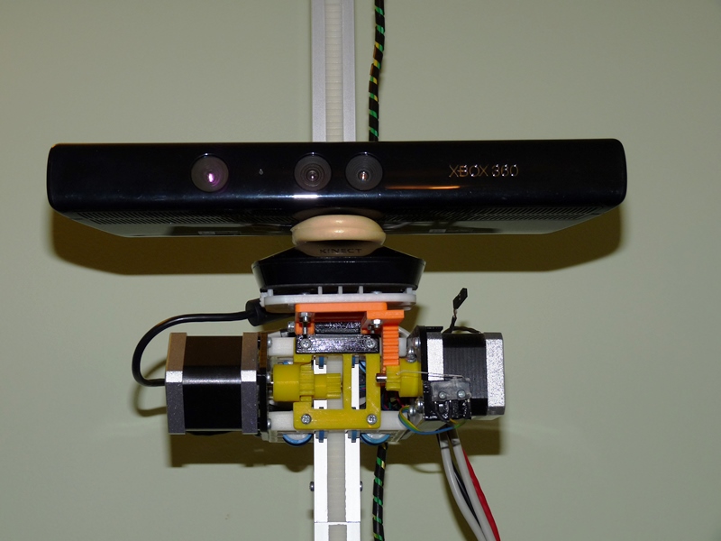
The pictures show not an audio amplifier, but an irrigation controller, just audio connectors are very convenient for connecting low-current loads.
UPD. Thanks to UFO for taking the community on board and to all the participants for the warm welcome :)
And of course the files, I save time for inventors)
How to design cases with locking joints and print them on a 3D printer
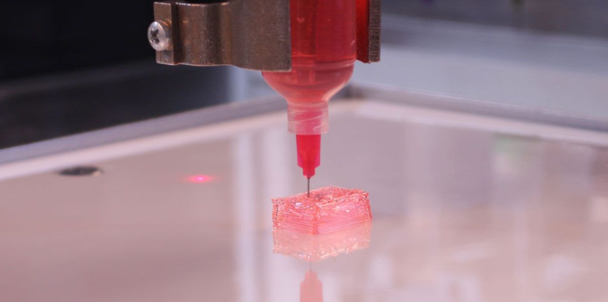
If you are a product designer or engineer, at some point you may need a case of an individual design. This could be a simple container to organize small items, or a fully working 3D printed prototype for demonstration to interested parties or testing before moving on to injection molding.
Using CAD software and desktop 3D printers, you can create an enclosure with interlocking latches in just five easy steps.
Technical report
How do I create custom-made enclosures with exact dimensions? Learn more about stereolithographic 3D printing by reading our free white paper Introducing Desktop 3D Printing with Stereolithography.
Download white paper
Measure your electronic component (left). Begin your 3D model with basic boxes (right).
Measure electronic components (left). Start building your 3D model with the standard boxes (right).
In this project, we will create a case for a Pine 64 single board computer (download the STL file from the Pinshape website to repeat the steps on your hardware). In this article, we're using SolidWorks, a popular design and development software, but you can use a similar 3D design software.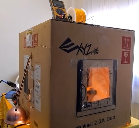
First take a digital caliper or ruler and measure the electronic components. We like to start case design by accurately reverse engineering the PCB, determining its dimensions, mounting hole locations, and any connectors or plugs that will need to be accessed through the case. You might want to just measure the maximum box dimensions, but it's important to know exactly where the main components are so they can be placed correctly. Reproduce these measurements in SolidWorks by laying out the boxes in a single model file.
In SolidWorks, an enclosure is best designed as an assembly model, designing the halves as separate parts. Create a new part that will be the base of the body. The first important decision to make is to determine how much distance is allowed between the PCB perimeter and the package. It depends on the 3D printing technology you are going to use. 3D printers based on SLA and SLS technologies are highly accurate, so you can safely set a tolerance of 0.5 mm.
Desktop 3D printer based on FDM technology can deform your structure and lift it off the platform, so you need to allow for a higher tolerance of 1.5-2 mm. This will guarantee the placement of the printed circuit board in the case, even if its walls are slightly deformed.
Check out our detailed guide comparing FDM vs. SLA 3D printers to see how they differ in terms of print quality, materials, application, workflow, speed, cost, and more.
Leave a space between the edges of the electronic component and the housing (left). Create the walls of the bottom of the hull in the 3D model (right).
Next, you need to make holes for the connectors. One common mistake is to cut a hole just large enough to access the connector, be it USB or HDMI, without considering that the many cables around the plug connector can be quite bulky and have to be inserted into the case to connect to the connector (especially if the connector is on a printed circuit board).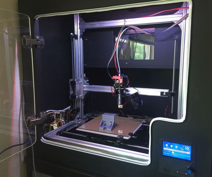 board is at a greater distance from the case). Therefore, it is better to make larger holes for connectors. You can add from 2 mm around the perimeter.
Add cutouts and holes to the bottom of the housing for the connectors.
As you can see in the image above, we've included cutouts that go all the way to the top of the part and one hole for a Micro SD card. Some of the cutouts reach the top of the part because the connectors on the PCB protrude beyond the edges of the part, otherwise the board would be very difficult to fit into the case. Some of these cutouts will be covered by the top half of the case, but you can make the bottom half larger to accommodate the entire PCB and connectors. Just keep in mind that you will have to insert the connecting cables deep into the case.
As a rule, the shape of the upper part of the case mirrors the shape of the lower half.
If you have finished designing the bottom part, you will have no problems with the top one.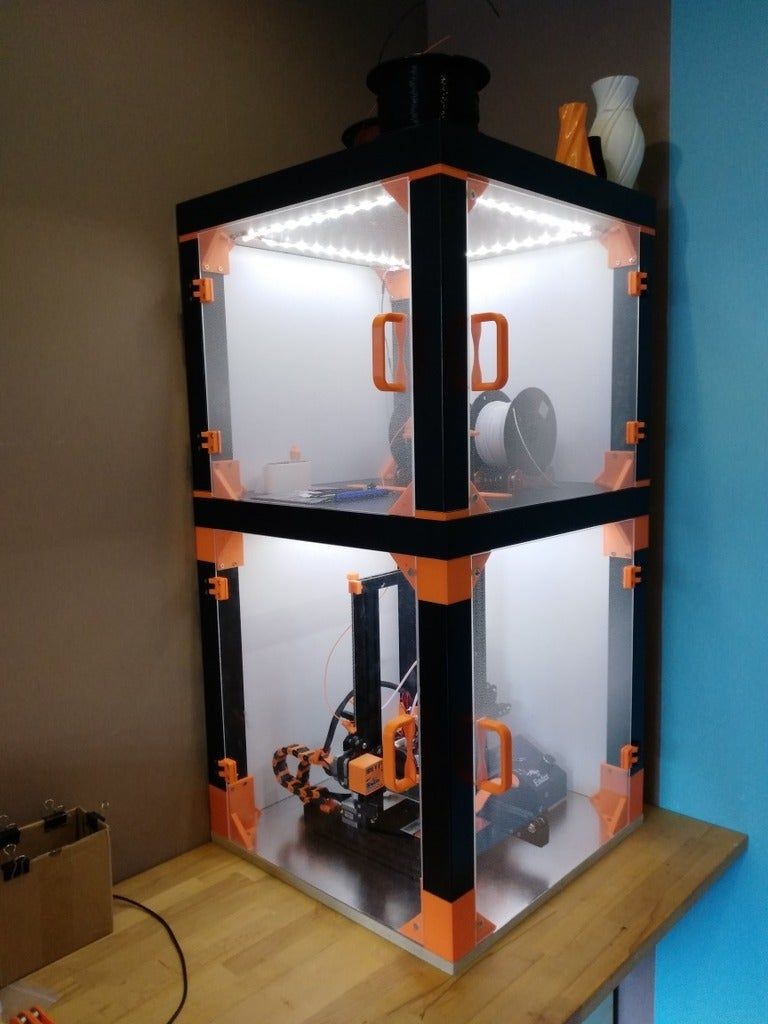 The image above shows the effect of a decoupling line running along the perimeter between the two body halves. The top of the case should have similar cutouts for tall connectors, and more material where it meets some of the cutouts in the bottom half. In addition, we have added an additional recessed part in the middle.
White Paper
Tolerance and fit design reduces post-processing time and simplifies assembly, as well as reduces material costs per iteration. Download our white paper to learn more about tolerances and fit in 3D design and production models.
Download white paper
The standard internal cantilever latch allows the lock to be extended for a stronger hold.
From a variety of snap-on component designs, we settled on a standard internal cantilever connection. The image above shows the main parts for the interlock, absolutely identical on both halves of the housing (male and female components). Depending on the working space available, the small protrusion inserted into the lock cavity can be lengthened to improve grip.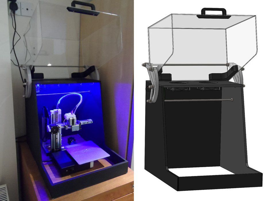 In our model, its length is only 1.2 mm, but with a length of 2 mm, the lock would be much more secure. In this particular design, the pins on the PCB take up a lot of space, so the lock is designed to simply push in while still providing enough force to secure the case. The console connection has a 20 mm protrusion, which increases its reliability.
This sectional view shows details of the lock on both sides.
The illustration above shows the components of the locking joint and the location of the pins (in black) on the PCB that limit the size of the cantilever joint. Instead of placing the snap-on elements inside the lower housing, it is also possible to place the protrusions in the through holes, which will increase their length.
The tabs are small protrusions that are inserted into the opposite side of the case, fixing both halves.
Add petals to your design to keep the halves from slipping. Petals are small protrusions that are inserted into the opposite part of the body.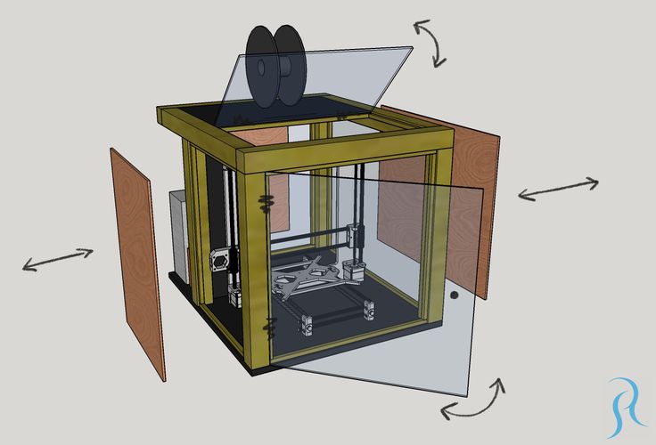 Since we have created two interlocks on opposite parts, they will only be needed on the two sides where there are no interlocks. This case is large, so we put them in every corner. The material protrudes only 3mm, but that's enough to prevent movement of the 3D printed parts that have been bonded.
This standard lockable housing can be adapted to almost any small electronic component.
While this may be enough for your project, a few extra details will help bring your 3D case to life. We added indented text to this project for the Pine 64 name and details such as the SD card slot. We added the Pine 64 logo not only for beauty, but also for ventilation, as these boards can get hot. In addition, these parts save material used for 3D printing. Finally, a pair of embossed lugs next to the latch connections help you determine where to push to open the case.
The final design of the snap-on case incorporates all of these unique features and is ready for 3D printing.
Stereolithographic 3D printing allows you to create accurate models and prototypes from a wide range of engineering polymers, reducing costs, speeding up development cycles and raising market standards.