3D printer axis orientation
How Does Part's Orientation Affect 3D Printing?
Have you ever wondered how the orientation of 3D printing influences the finish or the qualities of the part?
On some models the orientation can be very obvious, since the model designer him/herself sets it in the optimal orientation. In other cases we are not so lucky, and the model is positioned in a way that is not appropriate for its printing.
Do you want to learn how to orient your parts to get the best surface finish? Or maybe you prefer a higher resolution in certain parts of the model? Are you looking for the orientation that will maximize the model’s durability? Well, if the answer is yes, keep reading because we’re going to tell you all this and more today, at Bitfab.
📖 What do you want to read?
The importance of orientation
First of all, you may be wondering why it is important to find a proper orientation. Can’t we print a piece in any orientation? Well, technically yes, we could, but it may not be the best idea to choose an arbitrary orientation.
The orientation of the piece can have a great influence on several factors that we will explain in detail:
- The surface finish
- The “resolution” of the piece, or its level of detail
- The resistance
Depending on which section you want to focus on, you will have to choose one orientation or another. Below we will leave you with a few tips so that you can make the most appropriate decision.
Best orientation to improve the surface finish
The finish of our parts will depend mainly on two factors: the geometry of the part and the number of supports required.
We all understand that supports, although they can be adjusted to be as little intrusive as possible, will always leave some mark on our model. In turn, we can increase the unsupported overhang threshold, i.e. leave sharper overhangs without support. Depending on the layer ventilation of our printer the limit for these overhangs will be between 45 and 75 degrees.
There are parts like this one that will help you find the limit angle of your printer.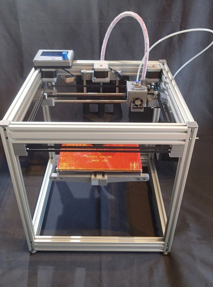 We will use this model to show you how proper orientation can improve the surface quality of a part by reducing or eliminating the need for supports or overhangs.
As you can see, by choosing the orientation on the left, we are forcing our piece to have very pronounced angles, which will probably need supports. Even if we don’t use supports, as we have done, the finish obtained in that area is very poor.
On the contrary, when we print the piece as seen on the left, there is no overhang, since the piece is lying down and all the walls are perpendicular to the bed, not needing supports or abusing the overhangs. You can see the results for yourself.
Best orientation to get a higher level of detail
To understand this point it is important to remember the “resolution” or level of detail that our printer can achieve in each axis.
In the XY plane, i.e. the horizontal, our printer is limited by the size of our nozzle. As the plastic is melted through the nozzle, the width of the extruded line will be approximately equal to the width of the nozzle itself.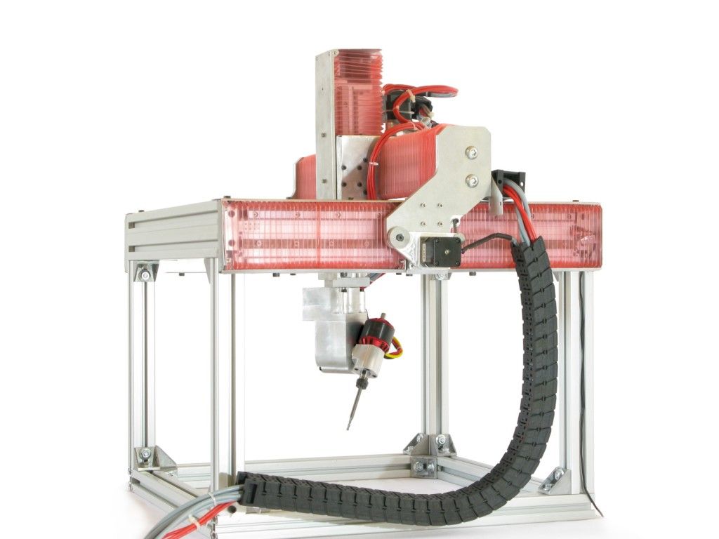 We can slightly enlarge or reduce the line width in our laminator, but it should always be close to the nozzle width.
This means that a 0.4mm nozzle will not be able to print much finer lines than 0.4mm, so the resolution in the XY plane is limited by this factor. Any part of our model that occupies less than this line width in the horizontal plane will be completely omitted by the laminator, disappearing from the final model.
If you want to know more about how the nozzle size and the extrusion width affect it, we leave you a video from Prusa where they explain it very well.
In the vertical or Z-axis, the resolution will be limited by the layer height we choose. The good news is that most domestic printers can print with layer heights as small as 0.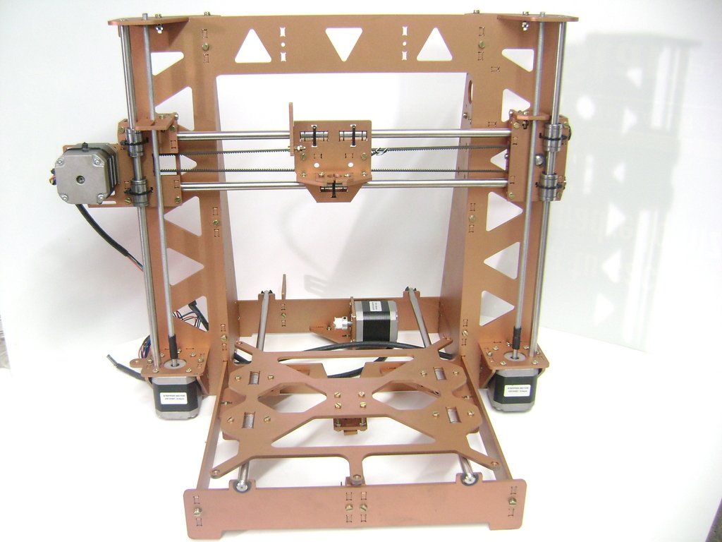 07mm, which is about 6 times more resolution than we could get in the horizontal axis with a 0.4mm nozzle.
This is why our goal is to orient the piece so that the smallest details are along the vertical axis. This may conflict with the previous point, since an orientation where details are located along the Z axis may imply a greater amount of supports so this is where we must find a compromise between both factors.
In the example we show you, we can clearly see that by orienting the model vertically, the areas with more detail such as the face or the beard retain much more detail, while they disappear completely in the horizontal model.
Better orientation to maximize resistance
3D printed parts will always be more fragile along the vertical or Z axis than in the horizontal plane. This is because the adhesion between layers is always lower than the adhesion between lines in the same layer.
If you are curious about the certainty of this fact, you can take a look at CNC Kitchen‘s Youtube channel.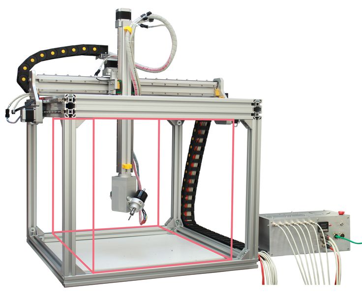 In many of their videos you can find comparisons of resistance between printed parts horizontally and vertically. The results vary depending on the material, temperature and other printing parameters, but as a rule the parts always tend to split between layers.
This is why to find the optimal position to maximize the resistance of a 3D model we must first think about what forces our part will experience. Once we have located the direction in which the force is going to be applied, we must orient our piece so that the force is applied perpendicularly to the layers, that is, the layers are arranged so that the force does not tend to delaminate the piece (to separate the layers).
We leave you a video of Maker’s Muse where a small study is made on the best orientation to print a piece so that it can better withstand stress in a given direction.
Conclusions
In this article we have explained some of the factors to take into account when orienting your models for 3D printing. As we like to make things clear, here is a short list with the most important tips:
- 3D printing requires supports to print certain regions with very pronounced overhangs. Try to position your model so that you minimize the need for supports, thus improving the surface finish of your parts.
- Parts printed in 3D with FDM printers always have lower strength in the Z axis (vertical) than in X or Y (horizontal). This is because the adhesion between layers is always lower than the adhesion between lines of the same layer. Orient your model so that the final part is resistant to stress in the direction that suits you best.
Now that you know these tips, are you ready to print? Leave us in the comments any doubt you may have or the models you have printed following our advice!
Best Orientation of Parts for 3D Printing – 3D Printerly
With every 3D print, there are several ways you can position a model on your print bed. This is also known as part orientation and there is a way to maximize your benefits by using orientation in a smart way.
This article will explore how to get the best part orientation and just what kind of benefits you can look to gain.
The best orientation of parts for 3D printing are ones which reduce Z height, minimize the presence of overhangs so less support materials are needed, and take into account where structural weakness may arise in the X, Y & Z axis. This results in faster printing times, less material used & stronger parts.
In this article, I will let you know the factors to take into account for the best direction of parts for 3D printing. These will make your 3D models accurate and robust with an excellent surface finish.
Requirements for Best Part Orientation
- First Layer/Foundation
You need to first look at what is required when deciding on your best part orientation. Even though many factors may make sense in a particular orientation, there are things to keep in mind.
First Layer Adhesion
Accounting for the height or support material aren’t the only things you should take into account. Another important consideration is your first layer adhesion. This stems from having a first layer which is large enough to have a strong foundation.
- To have a stable first layer, firstly, we look for large flat surfaces on the model.
- To print files with no distinct flat surface, you can either modify (cutting) the file creating a flat base
- Print using supports and a raft that will hold the print in place.
When the print is tall, and the first layer is fine or covers a minimal area, it is recommended to print with supports and a raft so that prints will be held in place.
Why is Orientation Important to Your 3D Model?
- Print Times
- Amount of Material Used
- Aesthetics/Looks
- Strength & Flexibility
- Part Accuracy
In this vast world of 3D printing, besides different aspects such as what material to use, what resolution to print at and even what infill pattern to use, an important element of modelling on your 3D printer is the orientation of your model.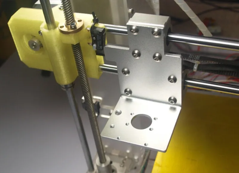
Compromises usually have to be made when deciding on the best part orientation, so decide this according to the goal of your printed parts.
This section will cover the main factors that you should look into for picking the best orientation for your model.
Effects on Speed & Print Time
3D printers extrude with higher speeds on the X and Y axes, as detailed by default printing speeds (acceleration & jerk) on slicers. The shifts that happen when your printer is moving up the Z axis need to happen slowly because these movements require more precision.
By minimizing the Z-axis or the height of your model, your 3D printer will be able to travel across the bed more efficiently resulting in your model printing much faster.
So, basically the lower your 3D print’s height is, generally the faster it is going to be printed.
The best scenarios for reducing printing times is where your printer reaches its maximum speed, taking into account acceleration and your set printing speed in the slicer.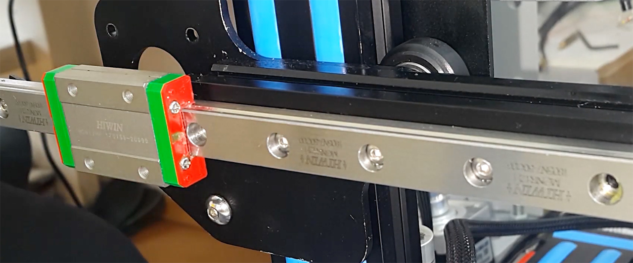
Also, when you think about just how many layers are being created for your 3D model, you quickly realize there are hundreds or even over one thousand layers being printed. If you have a layer height of 0.1mm and a model height of 180mm, that is 1,800 vertical layers that your 3D printer has to travel.
It makes a significant enough difference when we are talking about large models.
Changing the orientation for lower heights won’t work for all models with height due to other factors, but there are definitely some cases where it can be beneficial to you.
Sometimes a situation where you can decrease printing time might result in a failed print, or poor quality.
This would be an even bigger waste of time, so make sure you’re balancing the orientation of your 3D parts with the chances of success for getting to the end of a print.
Support Material Can Be Minimized
The ideal 3D print is one that doesn’t require supports because not only does it save on material used, but also on printing time.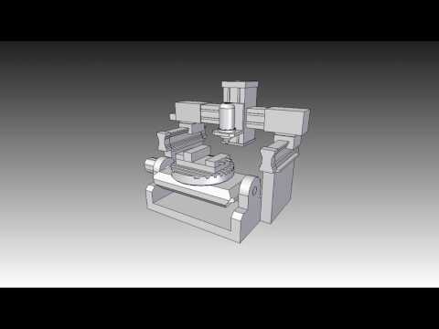
3D printing is a fairly slow method of manufacturing so our aims are usually to speed it up as much as we can, while having the optimal characteristics of an object.
Depending on the shape of your model, there may be overhangs which require vertical support towers to hold the surface up where the overhangs exists.
By using a certain orientation for your model, you can intelligently minimize support materials by changing the orientation to minimize overhangs. Doing this properly can save you plenty of support material over the years.
The angle where supports start to come in, is above that 45° mark as defaulted in the Cura slicer. In some cases with your models, you can angle your prints below 45° and have all the other sides at a good enough angle to print just fine.
This picture shows a model from Thingiverse called Orientation XYZ. It’s a nice example of using orientation to smartly reduce support material used.
These are all stood up in the same way they were printed and you can see, only one of them came out successfully.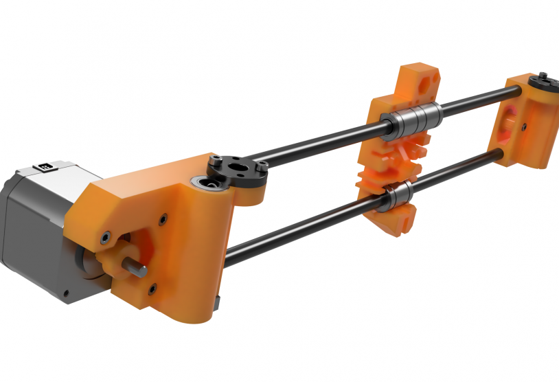 You can visualize why it worked so well and the other ones didn’t. It’s because of the way the previous layers are holding up the layers above, without any harsh angles.
Every time a vertical support tower is needed when there is an overhanging without any structure below it, build time slows down.
Build time will speed up when support materials are eliminated by changing the orientation to minimize overhangs, and you will save on support material usage.
It’s also ideal because I’ve had many 3D prints break on me while trying to remove support material so this works out even more in your favor.
If this has also affected you before, I’ve made a sweet article about How to Make 3D Printing Supports Easier to Remove, so check that out if you want.
Surface Quality Improvement
3D printers tend to print most accurately on the X and Y axis. By positioning your path in a certain way, the surfaces go down the X and Y axes and it will create a smoother surface and the best-looking part.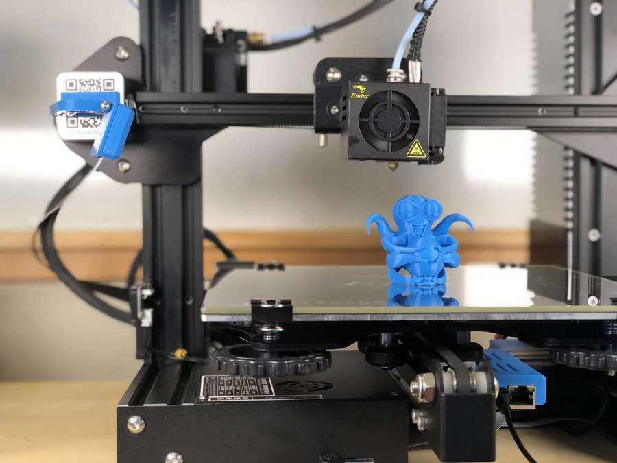
The less layer lines you have, the less ‘gaps’ you have in your model.
This means we can use orientation to make specific surfaces smoother.
You may not have noticed it but depending on which way your model is in relation to the base corner of your print bed, certain surfaces are better quality than others. This is where the best part orientation can make a difference.
The smoothest surface is usually the one that is directly on the print bed, especially on a glass bed.
Using this to your advantage, the side you want to be smooth can be placed in such a way that it’s face down, but only if it’s possible and makes sense.
The top of the print also usually has a pretty smooth print surface due to the tip of the extrusion being smoothed over. You want to try to avoid supports when surface quality is a priority because they tend to leave support marks and require post-processing.
Describing Best Orientation Using A Cylinder
The usual example when talking about surface quality improvements is when talking about a cylinder shape because the example is so clear.
When 3D printing a cylinder, the two main choices are vertically or horizontally. The better orientation would be one that makes the curved side of the cylinder the smoothest.
How do we make this happen?
Printed with a 0.4mm nozzle & 0.2mm layer height.Above, are three different orientations for a cylinder in corresponding order (left, middle, right):
A) The flat side opposite the curve faced down on the bed
B) The side curve faced down on the bed
C) The main curve side faced down
The picture on the right shows the final print. We can see that ‘B’ has the smoothest curved surface which is when the orientation was vertically placed. This is a situation where each previous layer is perfectly supported.
Each layer is creating the circular shape and shifts up one layer on the Z-axis, to create another layer of this shape.
A & C are not as smooth as A, with C being the worst of the three because it had the curved side being build upon a flat bed surface.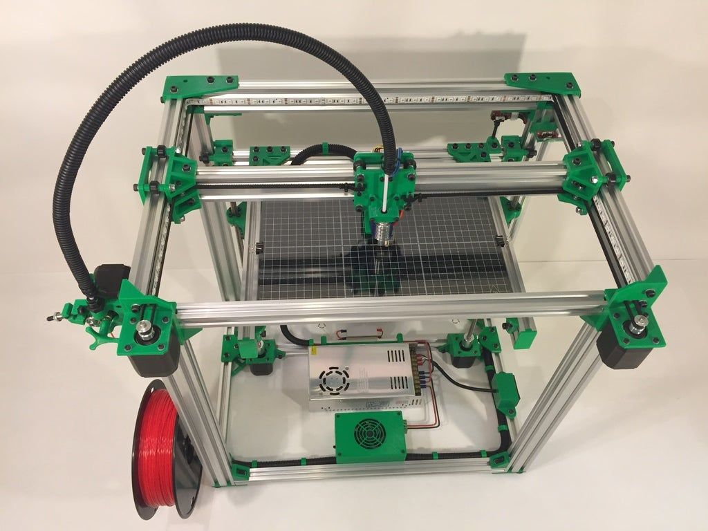
The horizontally-laid cylinder started off laying a thin rectangular strip of plastic for the first layer, then built upon that (C).
Then it will slowly be laying plastic slightly wider than the previous layer to create the outer circle shape, but be doing so in rectangles the length of the cylinder. This doesn’t give us the results we desire.
A foundation like this doesn’t allow the cylinder to build smooth, curved surfaces, or be properly supported to make smooth layers.
Depending on the use of your cylinder, B might not always be the preferred option. If this was designed to be some type of sliding mechanism , you wouldn’t want the layer lines to negate smooth movements along the curved surface.
If this was the case, either orientation A or C would be ideal because the layer lines follow the length of the cylinder which makes a smooth guided movement along.
To get better part quality, you would have to use a much lower layer height to smoothen out the micro-steps that give the bad surface finish.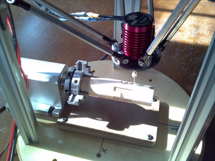
3D Print Orientation Strength
One of the main factors that 3D printing focuses on is the strength of printed parts. If 3D printed parts were weak and didn’t have strength to bear heavy loads, it wouldn’t be as popular as it was today.
This section will look at how you can intelligently have a part orientation which focuses on strength, rather than time, material or surface finish. Your 3D print orientation strength changes depending on how you set things up.
SparxEng found that by orienting parts in a certain manner, parts were substantially stronger regardless of the level of infill that was used. The part orientation that displayed this strength was an object that was printed flat, at a 45° angle front the X-axis.
It was because this angle gave the part multi-directional strength rather than just one directional layers going up and down or side to side across the part.
As we know, 3D prints are built up layer by layer, but we have to account for which way the layers are being built.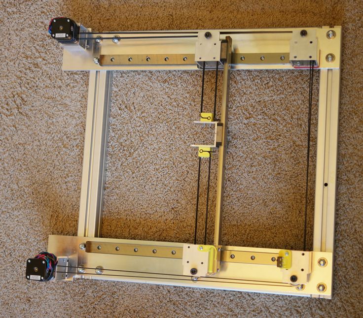
When you have a mostly vertical object, you don’t want your directional infill to also be going vertical because it means the part won’t have much horizontal resistance and will be easy to break.
Parts aren’t strong when their layer liens parallel the edges.
Even worse is having a long block and orienting the part vertically. This makes each layer built in the main direction of the Z axis which means your infill is going to be printed with a thinner surface area.
This is called having fewer flex points.
The Z layers can become separation points for a model when building in a layering process. The orientation of the part should be, so the flex happens along the X and Y axes if you are producing parts that require flexural strength.
3D printed objects tend to be strong in the X & Y axis direction, but weak in the Z axis direction.
When you orient a long block horizontally, there is a wider surface area being built upon.
Thinking about how 3D printed objects are layered down, the X and Y axis are extruded in long, continuous strips depending on the model.
On the other hand, when the print head needs to go higher, there is a layer change or shift upwards which means there is a gap between each layer.
It’s similar to having a long, thin stick and trying to break it. You wouldn’t try to break it vertically by pushing it down on itself because that’s where the strength lies. You would rather break it by bending the stick horizontally in the middle.
Part Accuracy
If you are printing a cylinder, vase or circular shape object your orientation has a big impact on just how accurately that part will be 3D printed.
This is all because of the way your printer builds up objects. It’s done layer by layer, which uses the foundation underneath as a supporting structure to carry on. If you have a circular object laid on its side, it will be built up diagonally rather than the required circle.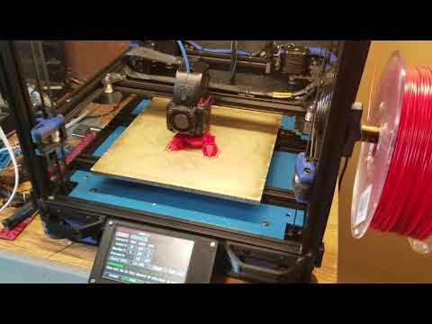 It will just be a series of angled rectangles to build up the sides.
Laying a cylinder or vase at an angle where the Z axis or height is used as the center, your printer will extrude each layer circle after circle, not having trouble with support or directional changes.
The best thing we can do for part orientation is make sure there is some kind of consistency in direction, for better print quality.
When we consider proper part orientation, we need to keep part accuracy into account and whether your part will be adequately supported to have proper precision.
Orientation also impacts on print time. By using the previous example, the build time of horizontal orientation will be less than the time to build the vertical orientation.
The total number of layers is significantly reduced at a 100-micrometer layer height. The horizontal cylinder will be printed with 100 total layers and the vertical with 300 layers.
How to Determine the Best Part Orientation
Now that we have identified what to consider, let’s look through how to put this information together to give us the best part orientation for your prints.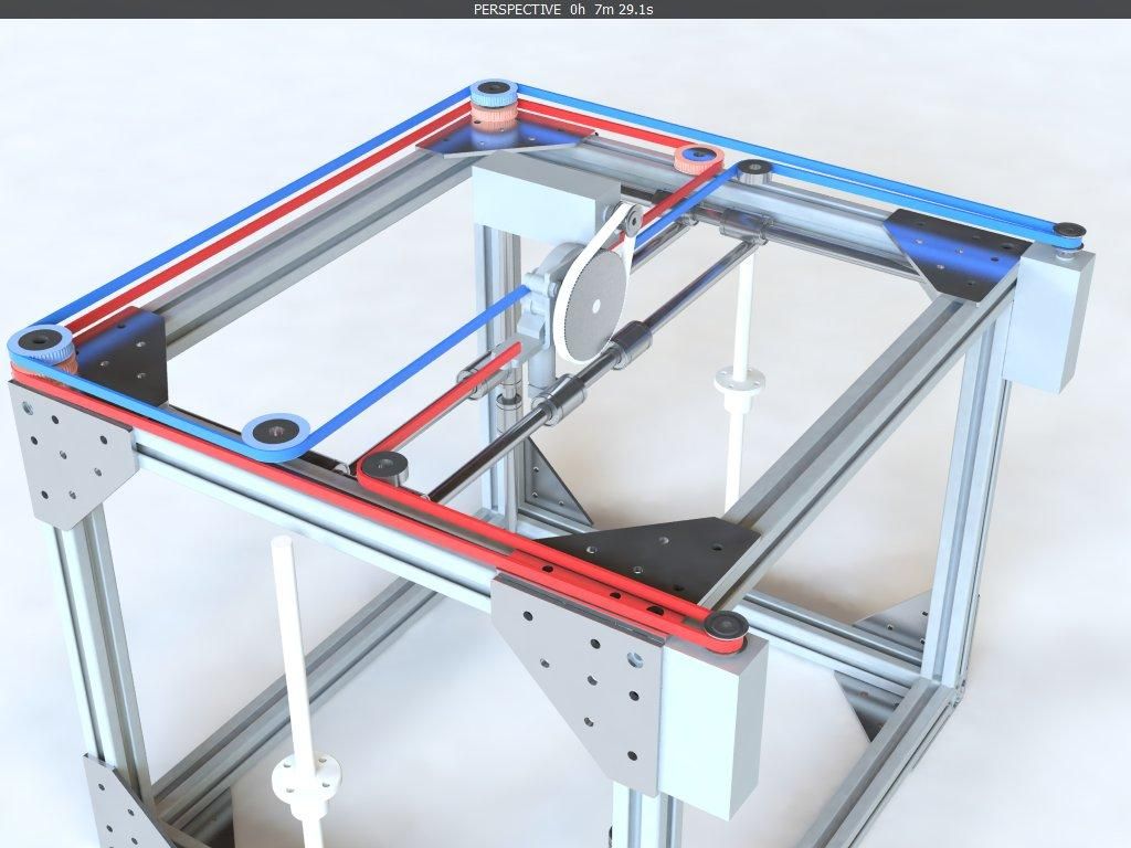
Manually Visualizing the Best Part Orientation
This video on how to orient a 3D print is a great one to watch by Maker’s Muse.
It takes some practice and critical thinking, but just by looking at a part you can pretty quickly decide which orientation is best.
Things can get complex, however, when we are looking at intricate designs so the main thing you’ll want to consider is the first layers and height of the model. Those are pretty good starting points before taking into account the other factors.
You have access to a ‘Preview’ module of your print and its layer lines so make sure to closely examine your layers to see if they are correctly oriented.
Try to prevent overhang by orienting the part in a way that makes it self-supporting and doesn’t extend past the main body.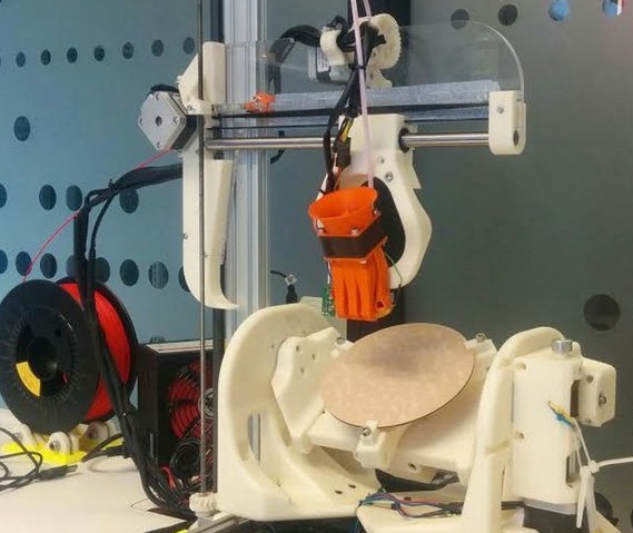
Software Modules to Help Determine Part Orientation
There are actually software tools that help people determine the best part orientation, but these are usually reserved for very high-end metal 3D printing machines.
According to Digital Engineering 24/7, one such software of the kind is called Sunata, which works with Direct Metal Laser Sintering (DMLS). It automatically decides the best part orientation as well as optimal support structure.
It works by separating the CAD model into segments, then running through around 100 possible part orientations and support structures, before picking the ideal one.
Orientation software are usually designed for metal 3D printing to make a number of critical changes. Warping is prevented by limiting the surface area of each layer so more control can be put onto the build-up of heat.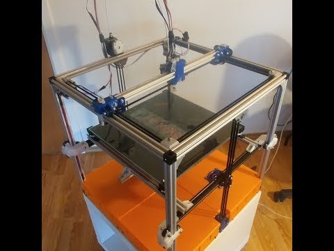
When you get significant temperature changes between two layers, it can ruin the build quality so these automated tools help prevent such things from happening.
Other Factors That Help Part Orientation
Minimizing Layer Lines for Orientation
The reason to look at layer lines when discussing part orientation is the ability of them to create a smooth looking part. Although a finer layer height does a great job at reducing the visibility of layer lines, there is a better way to do it without adding as much printing time to your model.
What you want to do here is use a part orientation that gives you the most level planes, rather than arching shapes such as cylinders and mounds. The reason this works is that a level plane builds directly on top of each other.
When there are different angles in a part, layer lines are separated which leads to that bumpy look you see in printed models.
An intelligently oriented model can minimize the presence of visible layer lines since they mainly show up in the Z-axis. If the part you want to print would look better with layer lines going in a certain direction, you can easily orient your model to do this.
It’s quite similar to the reduction of support materials section where you want an angle less than 45° but by using a lower layer height. You should think of layer lines as a flight of stairs, the smaller the stairs, the more number of steps you have to take.
But, rather than having stairs which have different levels, the stairs are just stacked on top of each other to create that smoother feel and look you are after.
Splitting Models into Easily Printed Parts
When it comes to large 3D printed models, splitting them is a necessary step since they can’t all fit on the bed in one go.
Rather than just blindly splitting models up, we can plan out and recognize the best way to split them by taking part orientation into account.
There should be a level of consistency in the part orientation so this will take some thinking, but with time you may be able to figure out a great strategy.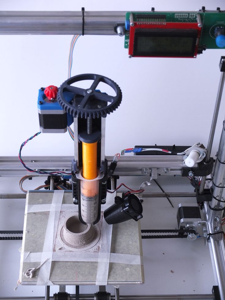
Summary
Many a time, there will be one or more orientations which are all appropriate however there will be cases where the most accurate orientation may not fit within your 3D printer’s defined build volume or match your needs.
In some of these cases, we may compromise certain aspects of the print, or perhaps we redesign or edit the file to better suit the printing process. By understanding each constraint and using these tips and tricks, we can prioritize, through taking advantage of orientation, the most critical aspect of our print.
We go down - we grow up, or the Z axis for cheap / Sudo Null IT News
Good day to you, dear geeks and sympathizers! This publication is a continuation of the description of the design of my homemade 3D printer. The Z axis is one of the most controversial printer nodes. What to choose - the ultimate accuracy or good scaling? Move the x-axis or the printer's desktop? Two approaches, two solutions.
I couldn’t look at the first 3D printers without shuddering: the designs were immature, many components were used in violation of specifications, because of the general fluctuation, constant adjustments, minor repairs were required, the size of the working field was small.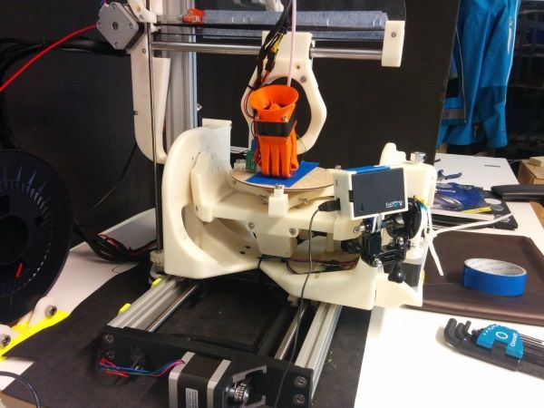 I decide to solve the problem of internal contradictions by simply crossing
 hedgehog with a snake portal milling machine and 3D printer designs.
The skeleton of a 3D monster was designed and twisted together:
It consists of forty-millimeter aluminum structural profiles connected by thick 45x45 corners and M8 bolts. This design has dimensions of 60x40x40 cm and is absolutely unshakable during normal operation of the printer. The size of the working platform was 45x22 cm, with a maximum height of 28 cm. The carriages are driven by precision trapezoidal screws mounted on angular contact bearings. Each screw is driven by a stepper motor via a 3:1 belt drive. The upper ends of the screws are turned and inserted into needle bushings so that the axial displacement of the screw in the bushing prevents it from wedging during thermal expansion. I used a polymer nut for the screws: there are no high speeds / loads, and the polymer nut is not so demanding on lubrication and is much easier to install.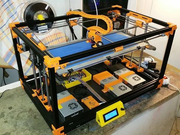 In this design, the height of the model is provided by raising the X-axis above the table, and the Z-axis is used as a movable support for the X-axis.
Operation video:
This axle worked without any problems until this printer was taken apart for parts.
Disadvantages of this solution:
1. Price. Precision components are expensive.
2. Design complexity
3. Poor scalability.
When I began to build the second printer, experience and stinginess were involved in the creation of the design along with an innate desire to go my own way, not expecting favors from nature. nine0007
Accordingly, the new printer had to become not only simpler, faster, more versatile, reliable and maintainable, but also much cheaper.
Instead of a screw drive, the Z-axis of the new printer was chosen, but a cable structure similar to a crane winch. It consists of the actual drive mechanism with a belt reduction gear and two blocks on which the entire mass lies along the Z axis.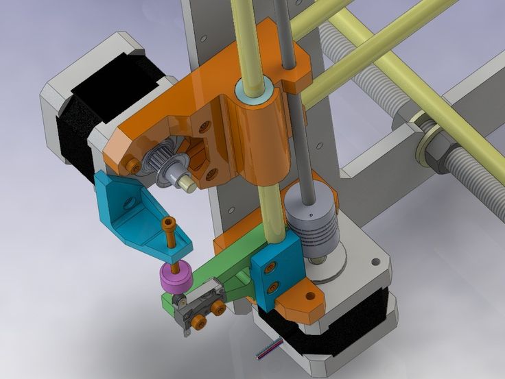
Here is a photo of the printer as a whole: paired plain bearings made of sintered bronze. nine0003 In the next two videos you can see the design of the winch, there is nothing complicated:
Z-axis skeleton: simple and lightweight design.
Power calculations: The drive drum has a radius of 10 mm. Accordingly, a torque of 0.3 Nm (normal Nema 17 motor) on a 10 mm lever will be 30 N. A belt gearbox with a gear ratio of 2: 1 doubles this number.
As a result, the maximum force that this winch can develop is about 60 Newtons, respectively, the maximum mass of the Z axis, together with the masses of the table and the object, should not exceed 6 kg at rest. nine0007
Now let's determine the losses for acceleration and deceleration of the Z axis: to accelerate 1kg of mass with an acceleration of 1m/s², it is necessary to apply a force of 1 Newton. In fact, an acceleration of 1 m / s² for the Z axis is quite enough, and each accelerated kilogram will cost us 1 N of applied force.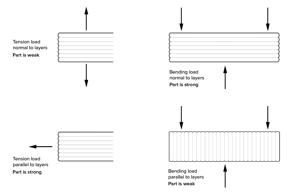
The heaviest element in the design is the heated table, it is a duralumin plate 350x350x3 mm, weighing 980 grams with glued heating elements with a total weight of 150 grams.
The rest of the structure, including Basotect thermal insulation, weighs approx.00 grams.
The total weight of the structure is about 2030 grams, which, when rounded up, will require 21 N for holding and another 2.1 N for acceleration. Total, once again rounding up, 24 N.
If we add a kilogram model to the mass of the Z axis, then 34 N will be needed, which is
slightly more than half of the rated winch power. It would seem that the design is redundant in terms of power. But the devil, as always, is in the details. The fact is that in order to achieve maximum torque, maximum currents must flow through the motor windings, which will inevitably cause it to overheat and prematurely fail. nine0007
For this reason, I designed the structure with a large power margin, and experimentally set the motor current a little more than the minimum required. At the same time, the motor heated up to 50-60 ° C, which is quite acceptable according to specifications.
In this video, the winch easily juggles the Z axis without a working table, but with two filament spools weighing 1300 grams:
So, the power issue is resolved. Now let's talk about accuracy. Given the parameters of the winch and motor components, with 1/16 microstepping, it is possible to move the Z axis in 0.02 mm increments. Now consider the problem of accuracy in a winch with a single-layer winding of the cable. The radius of the drive drum in my design is 10 mm, respectively, the circumference when winding will be 62.8 mm. It takes about seven turns to raise the Z-axis by 44 cm. When using a cable with a thickness of 1 mm, the axial displacement of the winding will be 7 mm. In this case, there is a change in the distance from the point of contact of the cable with the drum to the lower support block. nine0007
Let's calculate how bad everything is: the drive drum is in the center of one of the diagonals of the square formed by the bottom of the printer body. Accordingly, the drum is removed from each of the lower support blocks by 320 mm. By simple calculations, it turns out that when the table is moved by 440 mm, the drive geometry will change by 0.077 mm.
Quality trapezoidal threaded screws provide 0.07 to 0.4 mm accuracy at these distances. Simply put, they do not provide any meaningful gain in accuracy. If for some reason you need to print models with a height greater than 44 cm, you just need to proportionally increase the diameter of the drive drum (to keep the number of revolutions required to move the axis) and the gear ratio (to maintain the nominal load on the motor). At the same time, the cost of the mechanism increases slightly, in contrast to the design with a screw drive. nine0007
One of the test objects:
In conclusion, I can say that although experience is a derivative of the difficulties overcome and mistakes made, sometimes the process of acquiring it is more enjoyable than the results achieved.
There will be no 3D models because I can't find them on disk.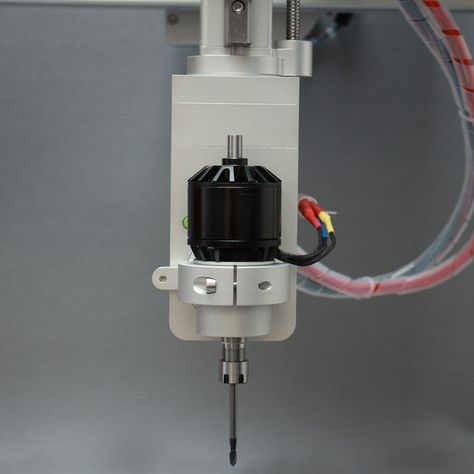
Published under the WTFPL license.
And traditional: Have fun!
FDM 3D printer
- 1 Description
- 2 General process
- 3 Structural elements
- 3.1 Housing
- 3.2 Extruder
- 3.3 Working platform
- 4 Preparing digital model
- 5 Seal
- 6 Application
Description
Fused Deposition Printing (FDM) technology has become widespread among individuals and small businesses due to its wide range of features, relative simplicity and good affordability. The popularity of this method deserves a more detailed description of the process and the printers used. In this section, we will look at the nuances of the design of printers and the application of technology in practice. nine0007
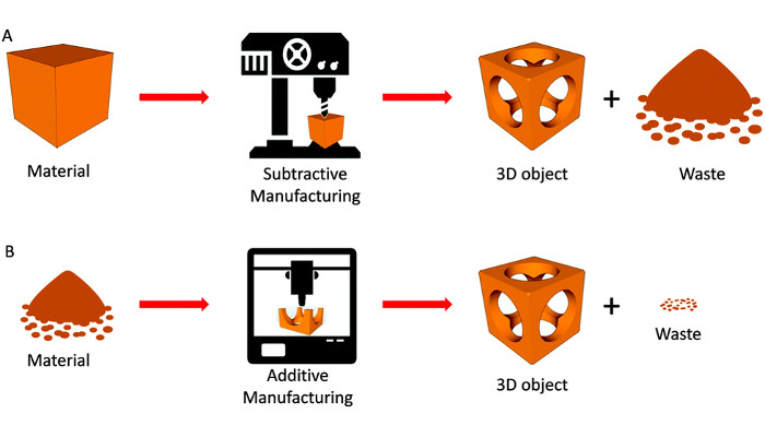
General process
Like all 3D printing methods, FDM belongs to additive manufacturing technologies. The term "additive" is an Anglicism from the word "additive", meaning "addition" or "by addition". The term is intended to separate technologies for the production of complex three-dimensional products that differ from the usual "subtractive" ("subtractive" - "due to separation") methods - milling, drilling, grinding, etc.
FDM can be considered one of the most technologically simple 3D printing methods. The process is based on the successive layering of a thin thread of molten plastic up to the creation of a solid three-dimensional object. A plastic thread wound on a spool is used as a consumable. Occasionally, individual bars of plastic are used. The standard thread diameter is 1.75mm or 3mm. nine0007
The printing process consists of a number of steps:
- Create or import a digital 3D model
- Processing of a digital model for printing with the addition of supporting structures
- Location and orientation of the digital model on the desktop
- Slicing - cutting a digital model into separate layers with data conversion into instructions for the printer, called G-code
- Directly print
- If necessary, physical or chemical treatment of the finished model
Structural elements
Enclosure
Ultimaker 3D Printer with exposed wooden case
Many elements are important in the design of an FDM 3D printer that are not always obvious to the inexperienced person.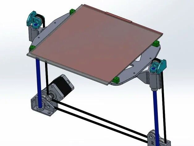 So, the material of the case matters in the event that it carries the load. Many FDM printers are available with wooden cases - this solution seems cheap and unsightly, but in fact it helps to absorb vibrations during printing, which has a positive effect on the quality of the manufactured models. On the other hand, a steel or aluminum frame ensures the durability and impact resistance of the device. nine0007
The open or closed design of the printer also matters. A well-ventilated working chamber is useful when printing with polylactide (aka PLA plastic), as this material vitrifies for a long time. If the printed layers do not have time to solidify and seize, they may spread, or deformation of the underlying layers under the pressure of the upper ones.
On the other hand, many popular materials (such as ABS and nylon) have a high degree of shrinkage. By "shrinkage" is meant the reduction in volume of the material as it cools. In the case of the same ABS plastic, excessively fast and uneven cooling of the applied layers can lead to their twisting, or deformation and cracking of the model as a whole.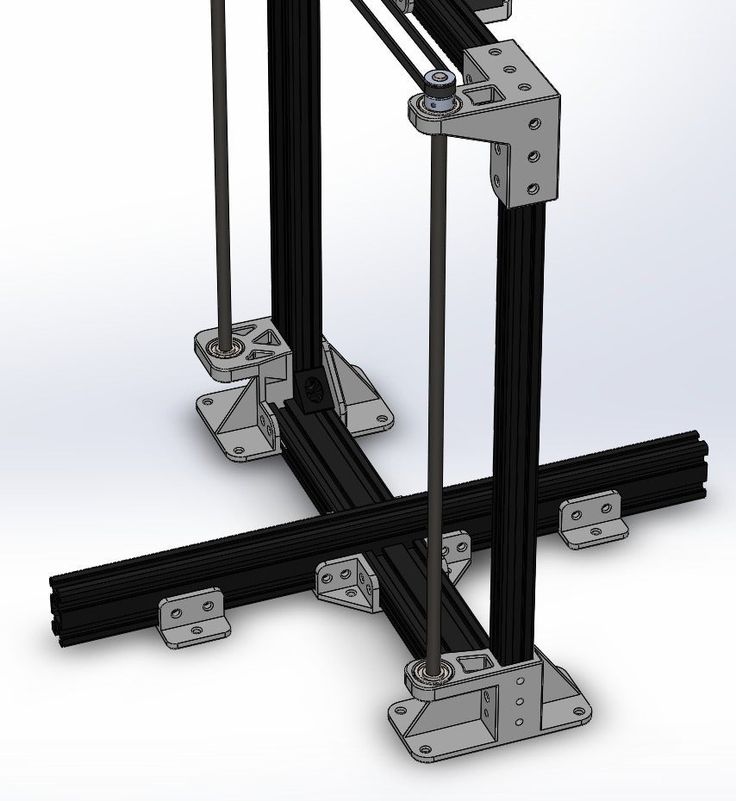 nine0007
PICASO Designer 3D printer with closed plastic case
In this case, the case with closed cladding comes in handy, allowing slow, uniform cooling of the material.
Finally, the shape of the FDM printer can also be linked to the coordinate system used.
Thus, the most popular option is the Cartesian or, more accurately in most cases, rectangular coordinate system.
Recently delta coordinate systems are gaining popularity - such devices are called "delta robots" and offer certain benefits in terms of printing accuracy and ease of expanding the vertical size of the construction area. nine0007
Structural elements and rails are usually made of aluminum or steel. The extruder and platform are driven by belts or screws.
3DPrintBox printer extruder, partially disassembled. You can clearly see the pink plastic thread and the pulling mechanism - two gears with grooves in the teeth
Extruder
The next important element is the extruder, that is, the printer's print head.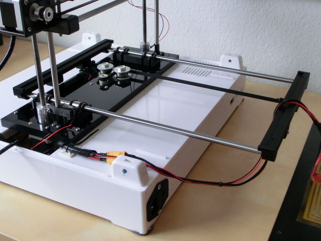 These devices may vary in design, but generally contain the same basic components: nine0007
- Feeder for feeding the thread into the nozzle
- Nozzle for melting filament and extruding molten material
- Heating element for heated nozzle
- Fan
As a rule, the pulling mechanism consists of gears or screws driven by an electric motor.
Obviously, the electric motor drives the gears to feed the filament into the nozzle. In the nozzle, the thread is melted, followed by extrusion of a viscous material. nine0007
An extremely important point is the sharp temperature gradient between the bottom and top of the nozzle - for this purpose the fan is installed.
At the transition of the glass transition temperature, the plastic becomes soft, but not yet viscous, expanding in volume.
3DPrintBox printer extruder in assembled condition.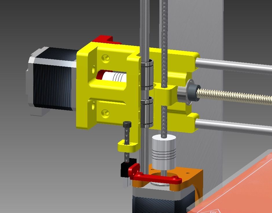 The electric motor of the traction mechanism is visible (top), double fan (middle) and nozzle with attached electric heating element (bottom)
In this state, the friction of the material with the inner walls of the nozzle increases.
If the length (and, as a result, the area) of this section is too large, then the total coefficient of friction may become unbearable for the pulling mechanism.
Thus, the length of the nozzle section with unmelted filament and the length of the section with molten material do not really matter, but the length of the plastic section at the glass transition temperature should be as short as possible. nine0007
The most effective solution to this problem is the use of heatsinks and fans to cool the filament and the top of the nozzle.
In fairness, the residence time of the plastic in the molten state should also be minimized, since many thermoplastics lose their ductility after prolonged exposure to high temperatures, and the resulting solid particles can clog the nozzle.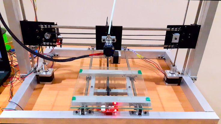
Diagram showing the transition of a plastic filament from solid to viscous. The length of the middle section should be as short as possible to prevent problems with material push through
Typically, this kind of problem does not occur in normal, stable extrusion because the nozzle length is too short.
Clogging of the nozzle can occur due to internal irregularities or errors in the manufacture of the thread: the resulting stagnation leads to the gradual formation of grains, which are then carried away by the flow of molten plastic and clog the outlet.
The most common nozzle materials are aluminum and brass. nine0007
Hole diameter may vary, but the average is 0.3mm.
Smaller bores allow for higher resolution, while larger bores increase build speed and reduce the risk of nozzle clogging.
Work Platform
The 3D Systems Cube 3D Printer Platform moves in the X and Z axes and the extruder in the Y axis
The work platform serves as a surface for building models.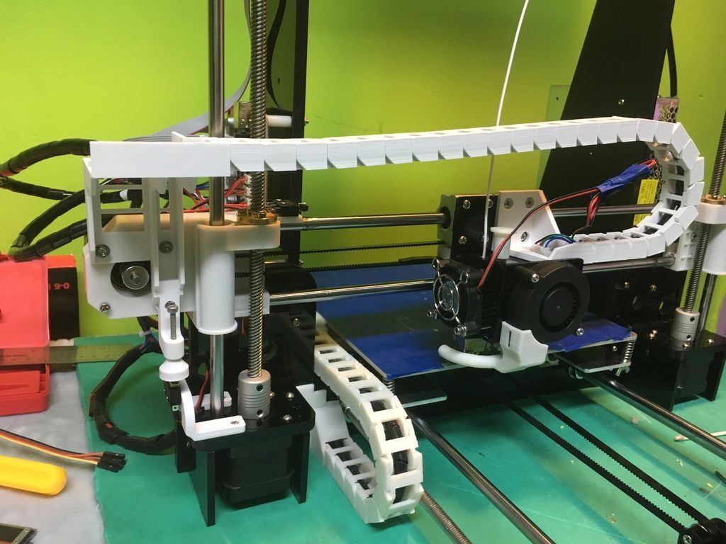 nine0007
Depending on the coordinate system used, the platform can be movable or static.
As a rule, in printers using the Cartesian coordinate system, the movement of the platform in the vertical plane is responsible for the vertical positioning of the extruder relative to the platform itself.
Some models also add movement of the platform along one of the axes in the horizontal plane, which allows you to slightly reduce the dimensions of the device, provided that the case is open. nine0007
An example of such printers is the popular 3D Systems Cube.
The delta robot work platform remains in place. Positioning of the extruder in three planes is carried out solely by the movement of three manipulators
Delta printers ("delta robots") use static platforms.
The positioning of the print head in all three dimensions is carried out exclusively by the movement of the extruder itself. nine0007
As a rule, the extruder is suspended on three manipulators, whose coordinated movement along vertical guides moves the die.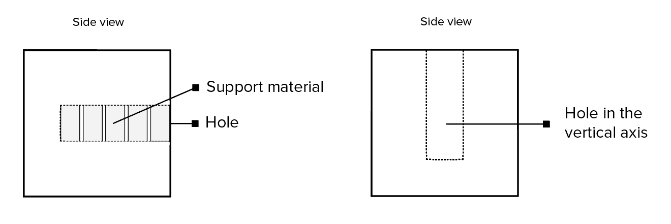
Asymmetrical movement controls the positioning of the extruder horizontally by changing the angle of the manipulators, and symmetrical movement - vertically.
Alternatively, a movable platform and a stationary extruder may be used, but these designs have not yet been widely adopted.
Experimental Quantum Delta Printer uses "inverted" design with moving bed and stationary extruder
A distinctive feature of all Delta printers is the cylindrical shape of the build area. One of the advantages of such designs is the ease of building up the working area. So, to increase the height of the building, you only need to install guides and cables of increased length.
However, even static platforms cannot be called completely immobile. Before starting printing, platform calibration is required, that is, the elimination of a possible tilt. Calibration mechanisms can be either manual or automatic, depending on the printer model. nine0007
In the case of manual calibration, the user will be required to sequentially position the nozzle at different points on the platform.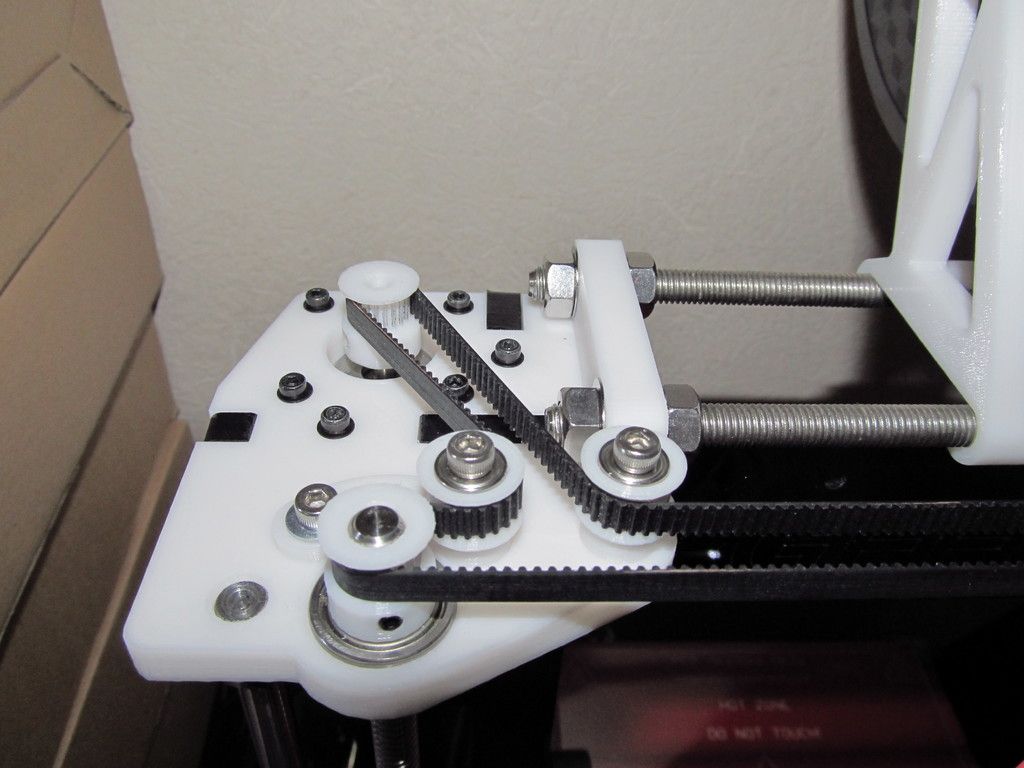
To measure the distance, special templates are used, and in the cases of the simplest or home-made designs, simply sheets of office paper, whose thickness corresponds approximately to 100 microns.
More advanced devices like the MakerBot Replicator use special sensors to accurately measure distance. Tilt adjustment is made by rotating the spring-loaded screws on which the platform rests. nine0007
Calibration of the platform is often done with the help of adjustment screws, although most printers help in this task by moving the extruder in succession to different points of the platform.
If the nozzle height is too low, extrusion will simply not occur.
If too large, the filament will not adhere to the surface and the printer will print "through the air", creating intricate filament filaments that have nothing to do with the given model. nine0007
A combination of these two effects can result from platform tilt. No matter how perfect the design of the printer, users are encouraged to trace the construction of the first few layers of the model.
Perforated printer worktable Up! Plus 2 provides good adhesion of plastic to the surface, but requires careful maintenance, as the holes are easily clogged
Depending on the design, the working platform can be equipped with a removable table. nine0007
This solution is often used in printers with closed housings that make it difficult to remove models from the platform or clean the surface.
In the case of perforated tables, this solution is simply necessary, since the surface is cleaned by soaking in solvents.
The disadvantage of removable tables is the possibility of backlash if the fasteners or clamps are sufficiently weak.
Heated aluminum platform with removable glass worktable for PICASO Designer 9 printer0141
When printing on certain materials such as ABS or nylon, the bed is equipped with a heating element. The purpose of the heating is to slow down the cooling of the lower layers in order to prevent their twisting caused by the shrinkage of the thermoplastic.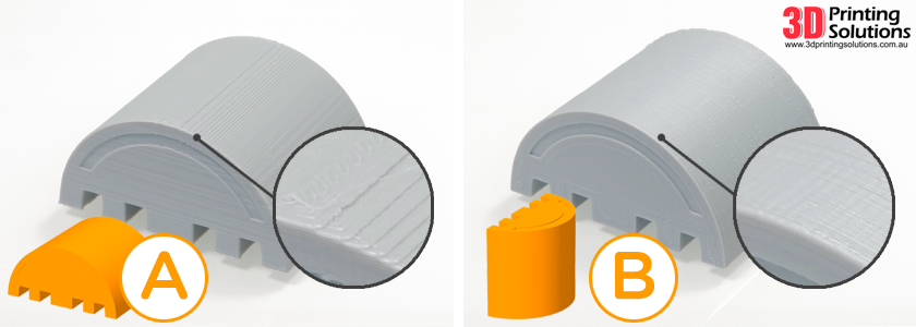 You can read more about this phenomenon and methods of struggle in the section "How to avoid deformation of models during 3D printing".
The materials used to make work tables are very diverse. Among them, aluminum, steel, acrylic can be mentioned - the presence of heating, of course, narrows the choice of materials. Glass has recently become a popular choice due to its high resistance to deformation and the ease of achieving a perfectly flat surface during production. Some manufacturers even use volcanic glass because of the low thermal conductivity, which slows down the cooling of the initial layers of the model. nine0007
Preparing a digital model
ReplicatorG, a popular open source slicer
Creating digital 3D models is not part of the 3D printing process. To create models, conventional computer-aided design systems (“CAD” or “CAD” in English terminology) are used, including 3D editors such as SolidWorks, AutoCad and LightWave, among many.
The process of preparing a model for printing begins with importing a 3D model in .STL format into a special program called a slicer. Such programs perform the functions of graphical editors, allowing you to add reference elements necessary to support model attachments. Many slicers allow you to add support structures automatically without requiring any effort on the part of the user. In addition, slicers allow you to place models on the desktop and change their spatial orientation. nine0007
Advanced programs also allow you to change the fine print settings - the thickness of the applied layer, nozzle temperature, take into account the consumable used.
The capabilities of slicers are closely related to the capabilities of the printers themselves. Some models have a "closed code" that requires the use of branded slicers. Some of the more popular open source slicers include Repetier-Host, ReplicatorG, and Skeinforge.
Building model support structures in Repetier-Host 9 slicer0141
After the digital model is placed on the virtual desktop, the necessary supports are created and the settings are made, slicing is performed directly - cutting the three-dimensional model into virtual layers with a thickness corresponding to the thickness of the applied plastic layers. Each such section will serve as a template for building a specific layer of the physical model. The end result is provided in the form of a G-code, a set of commands for a 3D printer that determines the movement of the extruder and platform during the printing process. G-code can be transferred directly from a computer using a direct connection, or written to a memory card or USB stick for offline printing, provided that the printer is equipped with the necessary interface and control module. nine0007
Printing
Some 3D printing enthusiasts make their own scrapers to remove finished models from the desktop
Printing can take quite a long time, often in hours. The duration depends on the speed of printing and the size of the models being produced. Print speed, in turn, depends on the complexity of the model, the perfection of positioning algorithms, layer thickness and nozzle diameter. Interrupting the printing process may result in the loss of the model.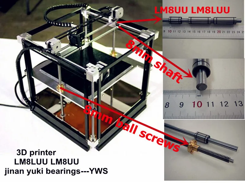 Although some printers allow you to temporarily stop the process to replace the consumable, a long pause will cause the upper layers to cool. When printing is resumed, subsequent layers may not "grab" with those already printed. nine0007
Fine scrapers are used to remove finished models from the table. At the same time, it is recommended to wait for at least partial cooling of the model in order to avoid damage to still soft layers or burns when touching still hot plastic. In addition, if you have enough patience, you can wait for complete cooling and shrinkage, which in most cases automatically leads to the separation of the model from the table.
Demonstration of support structures as part of the finished model
Depending on the working plastic, mechanical or chemical processing may be possible. Thus, models made of ABS plastic can be processed with acetone vapor, which leads to smoothing of roughness and printed artifacts, but can also lead to the loss of the most delicate features of the model.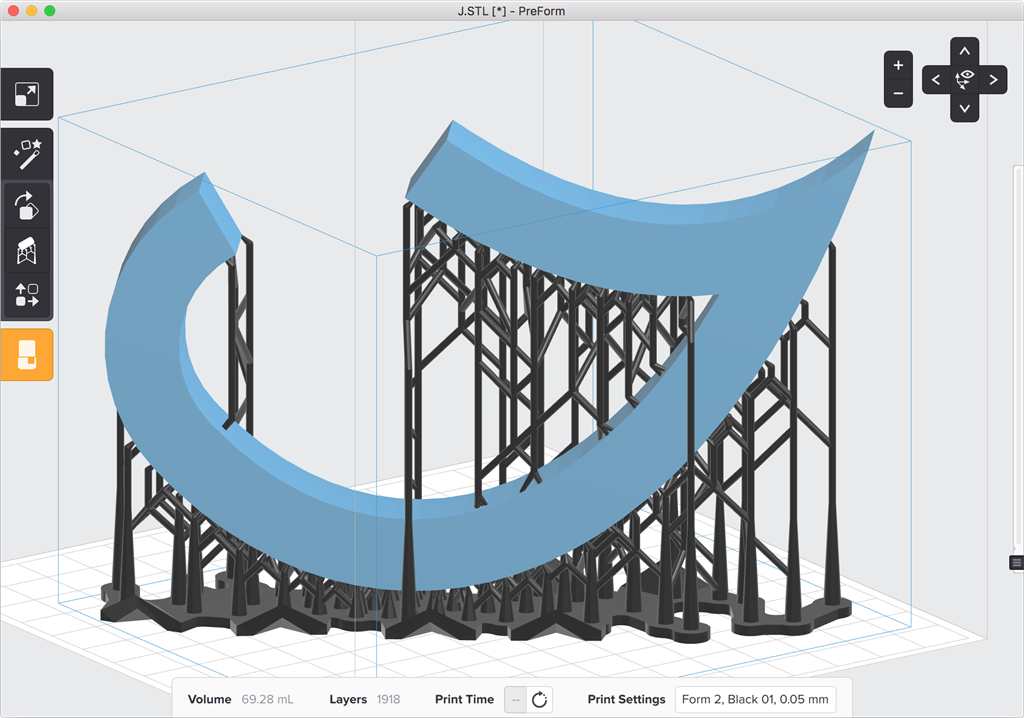 Basically, processing is reduced to the removal of supporting structures of hinged elements of the model. When printing on printers with a single extruder, the supports are made of the same material as the model itself, complicating the process somewhat. When using printers with two or more print heads, it is possible to build supports using water-soluble polyvinyl alcohol (PVA plastic). For more information on the plastics used in FDM 3D printing, see the FDM Consumables section. nine0007
Applications
3D printed controller prototypes for the Xbox One game console
The relative cheapness of FDM printers and consumables makes this technology widely popular. First of all, such devices are used for rapid prototyping. Various plastics allow you to create functional models of various products. Thus, ABS plastic, which is popular in FDM printing, is widely used in the mass production of various household products, automotive parts, tools, toys, souvenirs, etc.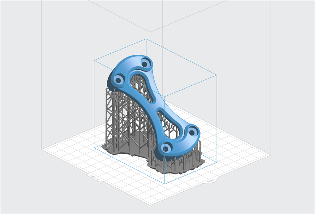 The sufficiently high accuracy of 3D printing makes it possible to obtain functional prototypes that practically do not differ in workmanship from traditional cast products. nine0007
The MakerBot Mini 3D Printer was designed for home and educational use
This application of technology allows significant savings in the development of new designs. Microsoft used 3D printing to create about 200 prototypes of the Xbox One controller, while Dell placed an order for 5,000 M200 FDM printers from Poland's Zortrax for use in affiliates around the world. nine0007
Although the productivity of FDM 3D printing is quite low, the relative cheapness allows the use of FDM printers for the production of small batches of finished products - souvenirs, toys, etc.
Improvement in technology and a significant reduction in the cost of devices allows FDM printers to gradually take root in everyday life. The benefits of 3D printing at home are clear—even fairly simple devices are capable of producing household appliances or broken plastic parts as needed.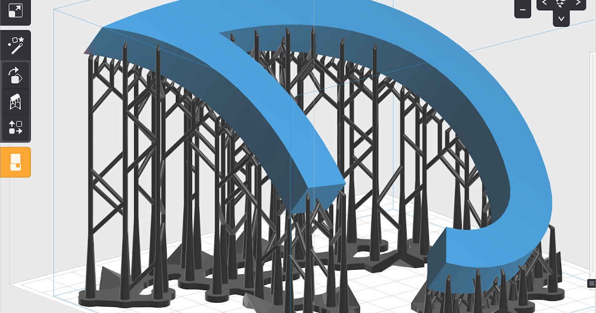 The cost of home production already makes such an application profitable in comparison with the purchase of finished products. The only significant obstacle to the widespread adoption of 3D printers in everyday life can be considered the reluctance of most people to go into the details of three-dimensional digital design. This barrier is gradually being eroded with popular services such as Thingiverse, Shapeways and Cubify offering a variety of print-ready 3D designs. Many of the available digital models are provided free of charge. nine0007
The 3D printed Liberator pistol called into question the ability of government agencies to regulate firearms
The Liberator pistol made a lot of noise. The design of this weapon includes one single metal element - the striker, which can be used as an ordinary nail. All other design elements can be printed. The design of the pistol has been released to the public.
Finally, the development of FDM 3D printing allows the development of an entire industry of 3D design and print-on-demand.