3D printed save button
Why is this floppy disk joke still haunting the internet?
Skip to main content
The VergeThe Verge logo.The Verge homepage
The VergeThe Verge logo.- TL;DR/
- Culture/
- Web
/
The ‘3D-printed save icon’ gag continues unabated — and celebrated
By Megan Farokhmanesh / @Megan_Nicolett
|
Share this story
There’s a joke that circulates online every few years. It’s a picture of a floppy disk, accompanied by the claim that a kid thought it was a real-life version of the “save” icon. Every time it pops up, people laugh, hit “like,” and marvel both at their own age and the cluelessness of kids today.
Over the last week, this gag has been making the rounds on Twitter yet again, thanks to a user under the name Bill Gross. His tweet went viral, with more than 174K retweets to date. The catch? There is no smart-mouthed kid in this equation. Gross was just repeating a laugh he’d once enjoyed.
Gross, the founder of a tech incubator, was watching a talk by Michael Wolf at the WSJ D.Live Conference, when he started pondering the progression of technology. While he was live-tweeting the event, the disk image drifted through his timeline. “I looked at it, and it brought back memories for me of my first floppies, multimedia PCs, and it made me feel a bit old,” he tells The Verge. He grabbed a new picture of a floppy disk, added his own spin, and hit Tweet.
Gross considered his message as more of a meme than a literal report of something that happened to him, though he admits he has no idea how this goof got started. Old iterations of the floppy disk meme are not hard to find. The oldest instance I’ve been able to dig up, circa a forum post in January 2014, comes from an unidentified web comic.
Since then, brands on Twitter have co-opted it in their usual attempt to be trendy. Tech bros have gleefully shared it with #humor hashtags. It’s even made its way into PowerPoint presentations, which of course have then been recycled for Twitter content. It’s appeared online in spaces like Reddit or Imgur. It even got a shoutout in a textbook.
The world is not full of clueless children repeating the same awed observation, though. It’s more likely that adults are just regurgitating an old joke. Floppy disks are dead technology; that’s hardly a new revelation. “I’m not sure why this meme resonates so much,” Gross says, “but I think it’s maybe because people have nostalgia about this time, and also it’s funny how the icon on the desktop survived so long after the floppy died.”
There’s a well-established fascination with antiquated tech and other bygones of people’s youth. From media outlets to daytime TV shows, people love to examine the passé things these darn kids today “don’t understand”: broken records, typewriters, landlines and telephone booths, the dial-up sound on the first modems, and so forth. YouTuber channels like FBE (formerly The Fine Bros) have built entire followings off this curiosity with their “Kids React” series.
There’s comfort in laughing at what kids today don’t know, because it suggests that those of us old enough to remember such marvels are not obsolete after all. There’s little reason for a kid to recognize a floppy disk for what it actually is, but we can pass our aging awareness off as intellectual superiority and rich life experience. Gross may be the latest, most popular example of the joke, but it’s doubtful he’ll be the last. The floppy disk lives on as technical shorthand instead of a physical object — that is, until everyone rightfully adopts the “ctrl/command + S” shortcut.
Most Popular
Bring back the Surface Book
The Witcher 3’s next-gen update makes a beautiful game much smoother
Westworld is leaving HBO Max
Elon Musk booed at Dave Chappelle show, claims it was only like ‘10 percent boos’
AMD Radeon RX 7900 XT / XTX review: 4K performance for less
UK turns to tweets and livestreams to manage 5-mile queue for The Queen
No one can stop you from spending $3,500 on a Samsung Odyssey Ark
Apple’s Lightning-only charging case for the third-gen AirPods doesn’t make sense
Google’s making it easier to add emoji in Docs
3d Printed Button - Etsy.
 de
deEtsy is no longer supporting older versions of your web browser in order to ensure that user data remains secure. Please update to the latest version.
Take full advantage of our site features by enabling JavaScript.
Find something memorable, join a community doing good.
(346 relevant results)
short tips for the transition from a CAD model to a printed object / Sudo Null IT News
was withdrawn from publication due to a technical error.Please be understanding. Thank you!
Whether it's just a hobby or a source of income, 3D printing is always based on product design. Those accustomed to traditional technologies will have to rethink the entire approach to product design and manufacture.
When the project is ready, a number of additional operations are performed: setting the orientation of the model and other parameters that ensure the proper printing process. In addition, it is necessary to take into account the fact that most 3D printers allow you to choose the degree of filling the model with cellular structures. The correct choice of this parameter provides protection of the object from deformation and destruction during the printing process, as well as significant savings in material and reduction in production time.
Finally, the last factor influencing the success or failure of the 3D printing process is the strength of the connection between the model and the table. If the workpiece is separated from the table during printing, then all the work will go down the drain.
Here, we'll walk you through the 3D printing process and give you some simple tips on how to use additive manufacturing in the design phase. In addition, we will dwell on the methods of preparing a finished project for printing, and also consider ways to securely fasten the workpiece to the table.
These guidelines apply primarily to Fused Deposition Printers (FDM) printers, but may apply to other types of printers as well. The process of obtaining a finished part by 3D printing is basically the same regardless of the method used.
Designing an object
Any 3D printing starts with construction. If you are developing a product yourself, then you need to build a 3D model of it in a computer-aided design (CAD) system to turn the designer's idea into reality. In this case, the object can be both very simple and very complex. However, too thin and too small models should be avoided.
3D-CAD from Siemens from this article for 49900r (90% discount), the promotion is valid until March 20, 2020. Read more>>
Saving the file in a special format for printing
To print an object, its model must be saved in a special file format - for example, STL, which has become the de facto standard in the world of 3D printing. In this format, model surfaces are represented as a grid of triangles. Simple surfaces are broken down into a small number of triangles. The more complex the surface, the more triangles you will need. Today, other formats are used in 3D printing, in particular, the 3MF format developed by Microsoft. But the most common is still STL.
CAD systems make it very easy to save the model in the desired format: just click the Save As command. To improve print quality, it is desirable to set a number of settings for saving to the STL format - for example, the tolerance during transformation and the angle of the plane. The lower the conversion factor and the better the angle, the smoother the printed part will be.
Opening the file in the slicer program
Most, if not all, 3D printers come with their own slicer software. The slicer loads the STL file created in the CAD system and cuts it into layers, and then creates a control program for the printer.
Place the model correctly in the print space
After entering the print settings, the model (or several models) needs to be placed on the printer table. You can print many objects on one table at once. At the same time, compared to printing a single object, the time slightly increases, but in general it still turns out to be less. Here are some tips for choosing the right model orientation.
Set parameters
In the slicer program, the user sets parameters such as print speed, material consumption, nozzle and desktop temperatures. Most slicers have simple settings for beginners. In this case, most often there are also advanced settings so that experienced professionals can achieve optimal results. Advanced settings include percentage infill, amount of backing material, and type of backing or raft (this is a small, thin base that keeps the printed part stable. The backing is removed when it's finished). The number of options is truly endless. Specific settings vary depending on the brand of printer. It's easy enough to set them up.
Sending the control program to the printer
After setting the print settings, the placement of future objects on the table, their orientation and quality, it's time to finally start the printer. It is enough to press the Print button and find something to do while the production is in progress. Depending on the complexity of the design, the process takes from several minutes to several hours.
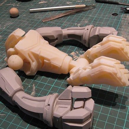
Finishing
Finishing includes removing the printed part from the table, as well as removing the support material by melting, mechanical separation or dissolution (depending on the design of the printer). The part may require some light sanding or polishing, but overall a properly printed object looks good from the start. Other types of finishing are placing plastic parts in a container with acetone to smooth out surface roughness, gluing (if the dimensions of the structure exceed the dimensions of the 3D printer or individual elements of the object must have different orientations), drilling holes and painting.
3D printing process
3D printer design considerations
Eliminate sharp corners
If the direction of the surfaces changes abruptly (for example, a vertical wall intersects with a horizontal overlap), then such a model is difficult to print. The printer will build excessive inner surfaces, wasting too much material. There are two easy ways to prevent this: add chamfers to smooth out where the surfaces meet, or round the corners so the printer gradually builds a vertical surface.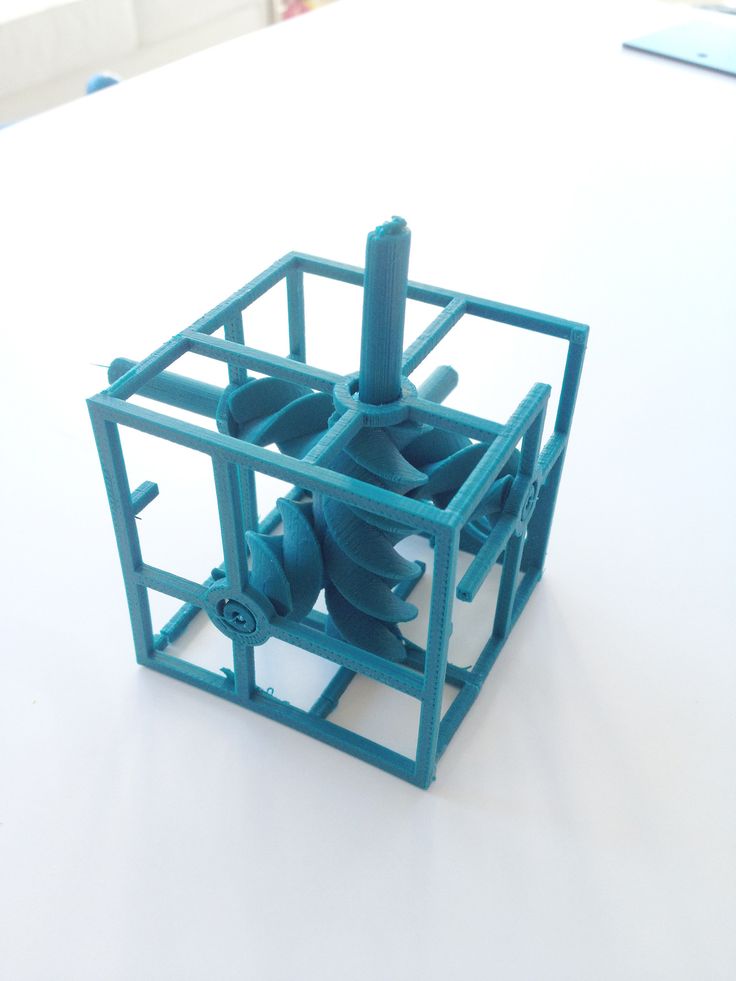 In addition, rounding will increase strength, since destruction most often occurs at sharp corners.
Elimination of thin walls and small geometries
Layer by layer fusing technology consists in supplying hot plastic through a nozzle with the formation of a printed object layer by layer. The thickness of the extruded plastic layer cannot be made smaller than a certain limit, depending on the diameter of the nozzle and the speed of the print head. Excessively thin-walled details are difficult to print - often the result is a chaotic weave of fibers. If the part can be printed, it is very fragile and breaks easily.
Too thick walls - also bad
On the other hand, if the walls are too thick, they become brittle and crack easily. This is especially important when printing from materials other than resins, as excess thickness during the manufacturing process leads to internal stresses in the part. Even when printing from plastics, material is wasted on walls that are too thick and time is wasted.
Removing large overhangs
3D printers allow you to create amazing shapes and surfaces, but they are not capable of printing directly in the air. If there is a void in the part with material above it, additional support material must be used. Most slicers add material automatically, but require you to specify the orientation and volume of the support structure. Printers with a single nozzle create an array of thin columns, which then have to be broken off. The result is an uneven surface. Therefore, it is recommended to avoid large overhanging elements whenever possible in order to reduce the need for support material.
If such an element is unavoidable, you can try to flip the object. Most printers are capable of printing overhanging elements with an angle of about 45 degrees. At a certain height, the edge of such an element may sag somewhat.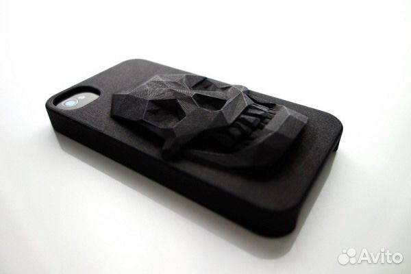 The actual capabilities of a particular printer are determined by trial and error.
Holes shrink
Remember that the part is made of heated plastic. As it cools, it inevitably shrinks. Therefore, holes and other critical structural elements have to be made larger so that after shrinkage their size is as close as possible to the required one.
However, if you need to make a tight tolerance hole, it is better to print it with a smaller diameter and then ream it with a suitable tool. This is especially true for holes whose axis is parallel to the printer table.
Increasing the footprint
If the area of contact between the object and the base is small, the part may separate from the table during printing. To prevent this from happening, wide bases are added to the model legs, which are installed on the printer table. In general, the closer to the table, the more material must be added to the support.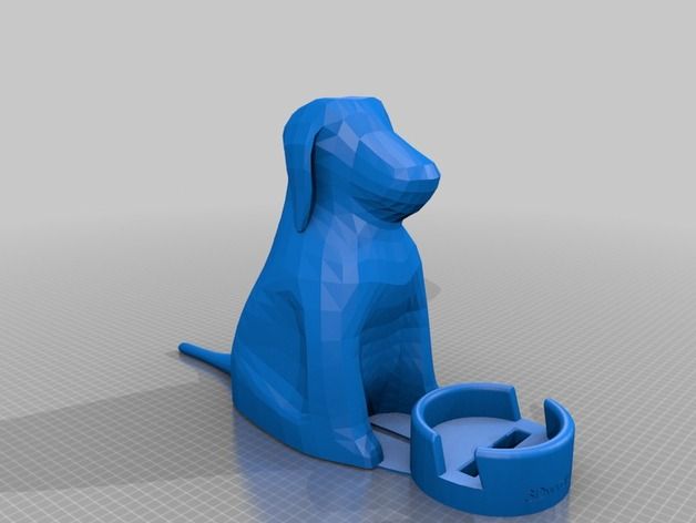 There are other ways to securely fasten the part to the table, which we will discuss a little later.
Special moves
The right approach to design makes printing easier. In addition, there are special post-processing techniques that are important to be aware of.
Place round surfaces vertically
The model should be oriented so that the minimum amount of support material is used. Ideally, it should rest on the table with a large flat edge. In addition, circular geometry must be placed so that the circular faces are vertical. If we look at the printer table from above, we should see a round silhouette of the object. In this case, the part comes out as symmetrical as possible with the formation of a solid round structure.
Place voids and holes vertically
If there are voids in the model (for example, it is a rectangular pipe), it is desirable to place such voids vertically in order to reduce the volume of the support material.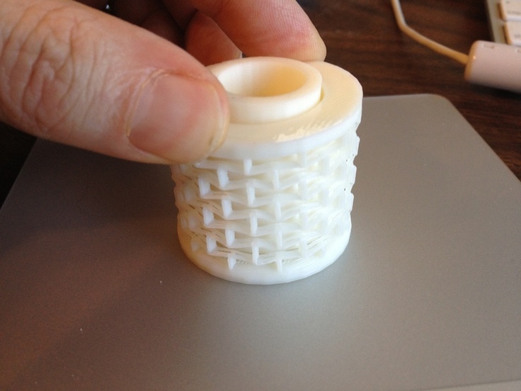 If you print the pipe in a horizontal position, you will have to provide support for the entire interior. If you put the pipe on the end, then no support is required at all.
The same is true for holes: to get a hole with a straight axis, it is best to print it vertically - in the form of a stack of rings, which avoids warping or deforming a round hole into an oval one.
Set print quality settings
Proper selection of print parameters, such as STL conversion tolerance and slicer software settings, allows parts to be produced with a surface quality that matches that of cutting. However, this entails an increase in print time. When choosing quality parameters, one should proceed from the purpose of the object: is it a finished product or a prototype? Will the part be visible or hidden?
The quality parameters also affect the shape of the holes in the part. In CAD files, holes are represented as a set of straight lines at an angle to each other.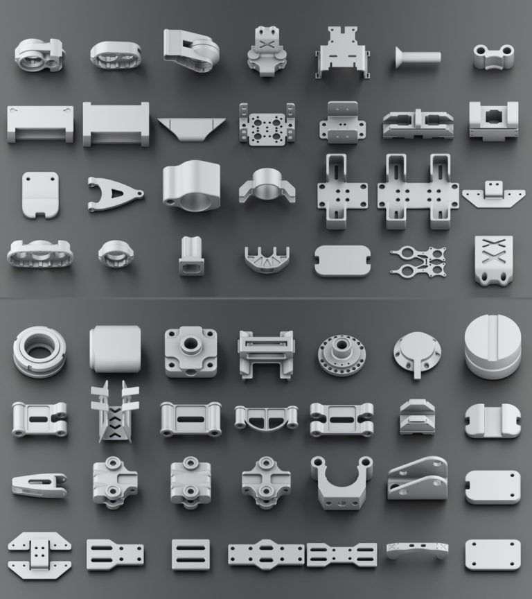 The higher the quality of the model in the saved STL file, the less the circle looks like a polygon.
Reducing the layer thickness
To obtain the best quality, especially when using layer-by-layer deposition technology, it is necessary to reduce the thickness of the layers. It does increase the print time, but the end result is worth it!
Optimizing the filling with honeycomb structures
In terms of strength, objects do not have to be solid. Similar to a honeycomb, printers can create a honeycomb infill that balances strength and saves expensive polymer material. However, if the printed part serves as a prototype for strength testing, and the serial product will be manufactured by traditional methods, and also if the part is subjected to certain types of mechanical stresses and pressures, a solid design will be preferable.
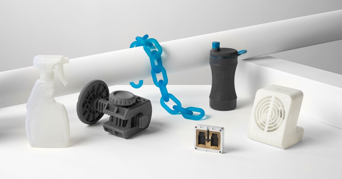
Choosing a material
The success of printing largely depends on the correct choice of material. Materials have different properties. For example, the melting point of thermoplastic polyurethane (TPU) and polylactic acid (PLA) is lower than that of acrylonitrile butadiene styrene (ABS). In addition, the material is taken into account when choosing the type of support structures. For an object made of polylactic acid, supporting elements can be made from the same polylactic acid, since it will be quite easy to separate them from the finished part. If the part is printed from ABS plastic, then the support elements must be made from a different material, and it is better not to use such elements at all in thermoplastic polyurethane parts.
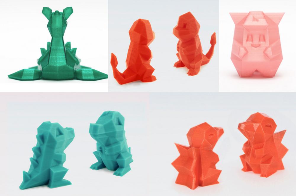
Cellular filling
A solid body is not always the best choice for 3D printing. Printing solid parts has its advantages, but the internal honeycomb structure saves both expensive material and time.
Creating objects with a specified degree of filling with honeycomb structures is a unique opportunity for 3D printing. Moreover, it is not required to design such a structure: this is done by the slicer program. As a rule, it is enough to set only the percentage of filling (the closer it is to 100, the more solid the object will turn out) and select the type of cells, if the printer has such an opportunity.
In addition to saving time and material, the internal honeycomb structure has many other advantages.
Cellular filling prevents warpage
Printing large objects as a single piece introduces a danger of warpage. By reducing the infill percentage, the air during printing passes through the part, providing more uniform cooling and eliminating warpage.
Cellular filling does not lead to loss of strength
Printing cells instead of solid material does not reduce the strength of the part. In many cases, a honeycomb part is strong enough for the chosen application, but lighter and less material intensive.
The function determines the choice of cell geometry
Most slicers support a wide variety of cell geometries. The optimal option is determined by the functional purpose of the object. Standard box padding simplifies printing, while hexagonal and triangular boxes add strength. Wave fill allows the object to bend or twist.
How to choose the right filling percentage?
In general, the strength of an object increases as the percentage of infill increases. Most printers have a default infill percentage of 20, which is optimal in some cases but too high or too low in others. Consider mechanical stresses in the printed object and increase the percentage of infill in areas where greater strength is required. If high strength is not required, choose the lowest possible filling. This saves material and speeds up printing. Most often, the selection of the optimal percentage of filling is done by trial and error.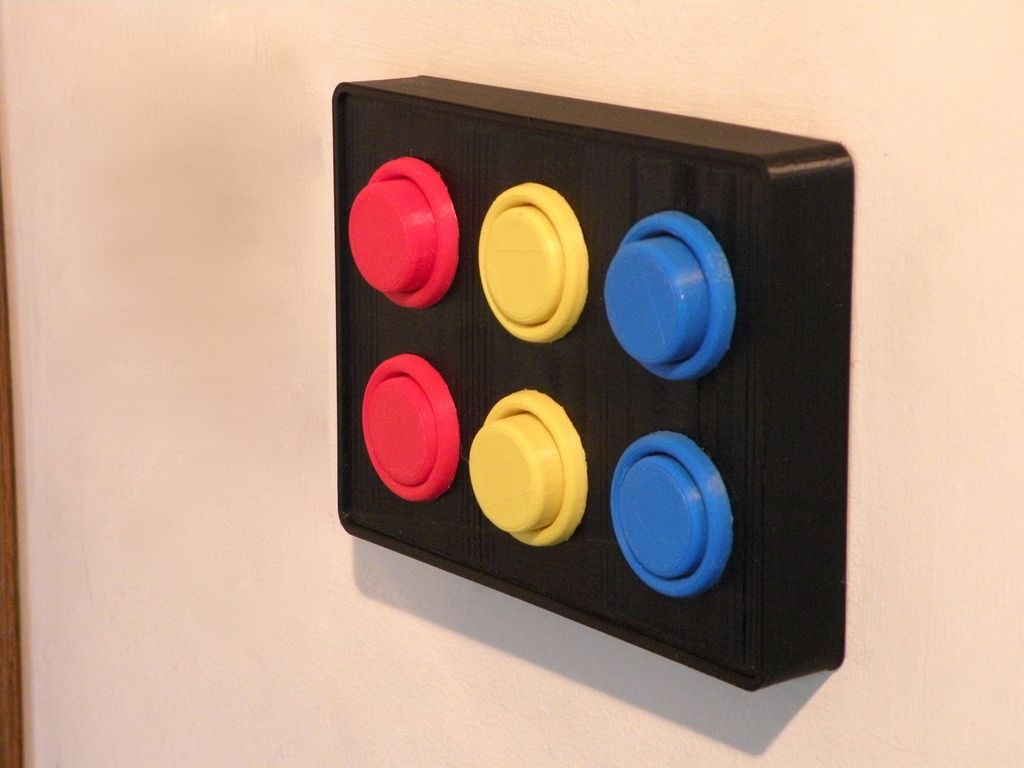
Ways of fastening the workpiece to the table
“Rafts”, “brims”, “skirts” – these terms sound funny, but they just refer to the three main ways of attaching a 3D printed part to a printer table. Let's take a look at each of these methods and their areas of application.
Skirt
The skirt involves creating a few rings around the object at the beginning of the print to make sure the plastic is extruded normally. The skirt is not in contact with the object at all. It surrounds the printable area and helps start the fusing process. When creating a skirt, a large volume of hot thermoplastic polymer passes through the nozzle. This prepares the printer for printing the part itself. This guarantees good adhesion to the table and obtaining smooth surfaces of the object.
Brim
The brim is a wide, flat area connected to the main object as a support base (think of a brim of a hat). It is very similar to a skirt, but connected to the model. In addition to all the advantages of a skirt, the brim keeps the edges of the object being made on the table.
When printing, the outside of an object often cools faster than the middle, causing the edges to curl. Brim prevents this phenomenon by holding the edges.
Raft
A raft is a detachable base, made in the form of a thin mesh platform, located under the entire object (which lies on the raft). To create a raft, the printer first prints a flat plate in two or three layers, and then begins to manufacture the object.
The rafts provide excellent adhesion to the table surface and also provide a strong print base. This is especially useful when making small and oddly shaped parts that do not fit well on the table, as well as thin-walled objects.
After printing is completed, in most cases the raft will separate easily from the part.
If the printer does not have a heated desktop function
Rafts are used if the printer does not have desktop heating. In this case, excessive adhesion becomes a problem.
An alternative method is to apply adhesive paper tape to the printer bed, with the edges down if possible (this also protects the bed). You can also use packing tape, but it is usually more expensive.
If buckling does occur or the object separates from the table, apply a dissolvable glue stick to the adhesive tape. This will enhance adhesion.
Find out the features of a specific 3D printer and take them into account when preparing a model
3D printing is not only a science, but also an art. Effective design for subsequent 3D printing requires an understanding of the technological process, taking into account its features and the purpose of the future object. This will greatly improve print performance.
Using Solid Edge in 3D printing
Not all CAD systems are suitable for 3D printing
The capabilities of the applied system should not limit the designers. Our Solid Edge system is designed with the latest 3D printing technologies in mind. Various 3D printers and 3D printing services are supported.
Take it to the next level with specific techniques for designing 3D printed parts
Generative modeling in Solid Edge opens up new possibilities: the designer selects a specific material, sets the design space, allowable loads, restrictions and target mass of the part, and the system automatically calculates the desired geometry. As a result, 3D printing methods can produce the most complex shapes.
In addition, when building models, the use of the results of three-dimensional scanning is provided. Solid Edge successfully combines the traditional boundary representation of solid models (B-Rep) and the representation of surfaces in the form of a grid of triangles, which avoids time-consuming transformations that are fraught with errors.
If you've already downloaded an STL file for printing, our unique synchronous technology makes it quick and easy to edit your imported models in Solid Edge in preparation for the process.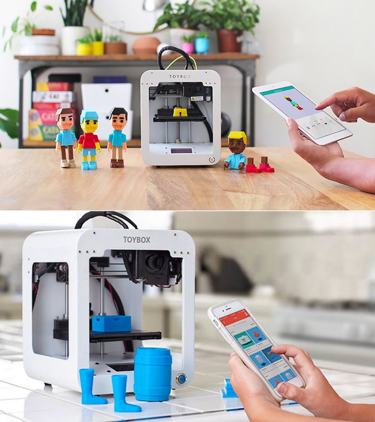
Printing with your own printer or submitting an order to a 3D printing service provider
Printing in Solid Edge on a local 3D printer is done using the 3D print command. Models can be saved in STL and 3MF formats, or sent directly to Microsoft 3D Builder. If you don't have your own 3D printer or need to try out different materials and surface finishes, Solid Edge allows you to directly submit your models to cloud-based 3D printing services (such as 3YOURMIND). You immediately receive quotes for the production of parts from various materials with its subsequent delivery directly to your door.
3D-CAD from Siemens from this article for 49900r (90% discount), the promotion is valid until March 20, 2020. Read more>>
Instructions for setting up all the mechanics of a 3D printer: from belts to speeds
The quality of the printed models directly depends on the mechanics of the printer, namely on its correct settings. Any elements of the printer wear out over time, so the printer must be set up at least once every 5-6 kg of printed filament. With the help of the short instructions described in this guide, you can quickly and easily set up the mechanics of your printer: belt tension, motor current, motor steps, acceleration, jerk and speed.
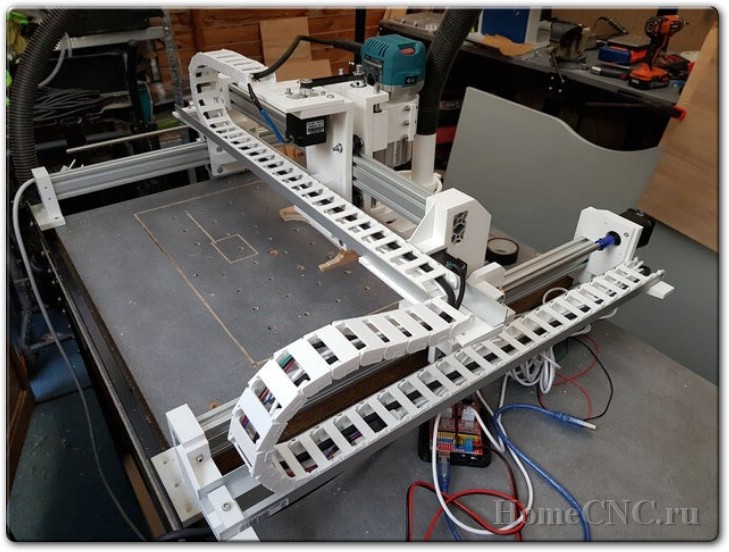
Mechanics includes
3D printers of any design always contain the same things: Axes and rails along which the elements of the printer move and motors with belts that set these elements in motion. In a classic printer design, there are at least 3 motors (one for each axis), 3 rails (one for each axis) and an electronics board that controls the motors. The latter can hardly be called part of the mechanics, but since it controls the engines, it also indirectly affects the quality of the model.
Printing defects due to mechanical problems
Before changing anything in the printer, you need to decide what exactly needs to be configured. Often defects are visible visually. Our blog has an article about most printing defects, which details the reasons for their occurrence. The following is a list of defects and what element of mechanics they are associated with:
-
Layer shifting - Belts, Motor current, Guides
-
Ringing - Guides, Speed
-
Incorrect model geometry - Guides, Motor steps, belts
As you can see, all the above problems do not interfere with the printing process itself, but the result leaves much to be desired. Sometimes mechanical errors can completely stop the printer from working. Therefore, it is better not to take the situation to extremes and, if any problems arise, immediately start checking and configuring the 3D printer.
How to save settings
To fix some defects, you need to change the printer software settings. Therefore, before adjusting the mechanics, it is necessary to understand how to properly store the settings inside the printer. There are 3 ways to do this:
All settings are located in the corresponding menu of the printer
Depending on your firmware, this manual will indicate code sections for MARLIN firmware in the configuration.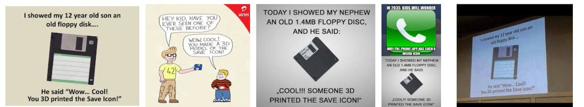 h file
We first enter the parameters into the printer and then store them in EEPROM - the internal memory of the microcontroller. Or paste all the necessary settings at the beginning of GCODE. To learn how to do this, read our article on working with GCODE and creating macros.
To save to EEPROM, you need to send the printer a command to change some value (which can also be inserted into the initial GCODE), and then send the M500 command (save the current settings to permanent memory). The EEPROM function must be enabled in the firmware, for this you need to remove two slashes in the line:
//#define EEPROM_SETTINGS
Whichever option you choose, you should be careful when using any commands. You will not be able to harm the printer in any way when changing the settings, but if you make a mistake, you will have to look for the cause of possible further problems for a long time.
Setup instructions
Now you can start setting up the printer itself. If you decide to set several parameters at once, then it is better to use the order of adjustments as in the article, since some of the settings are related to each other and if you use the wrong order, adjusting one element of the mechanics will override the settings of another element. For example, you should not adjust the motor steps before tightening the belts, as changing the length of the belts will change the "true" steps per millimeter of the motors. Also, before setting up, you must make sure that there are no backlashes in the printer frame, tighten all belts.
Belts
The first thing to start setting up the printer is the belts. They directly affect the geometry of the model and, when pulled too much, they cause a lot of problems: displacement of layers, changes in geometry, ripples. First you need to make sure the belt is intact. To do this, look at the entire belt, especially the areas where the belts bend. If the belt has outlived its usefulness, then you can see a section of the belt where the distance between the teeth has greatly increased and a metal wire (cord) is visible between them. This means that it's time to completely change the belt.
Broken belt with broken cords
If the belt is intact or you have already replaced it, then you can proceed to the next step. Depending on the design of your printer, you need to move the roller through which the belt passes. The tension should be such that the carriage or table moves effortlessly, but at the same time, when moving quickly, the belt should not slip the teeth on the motor gear. Adjust the tension of the belts on each axis of the printer using this method.
Tip: if your printer came with a belt tensioner in the form of a spring attached to the belt itself, remove it. Due to the flexibility of this tensioner, printing defects will occur, such as protruding corners on the model. It is better to adjust the belt without using this tensioner.
Belt tensioner
Motor current
As we know from the school physics course, the power of the engine depends on the voltage and current strength.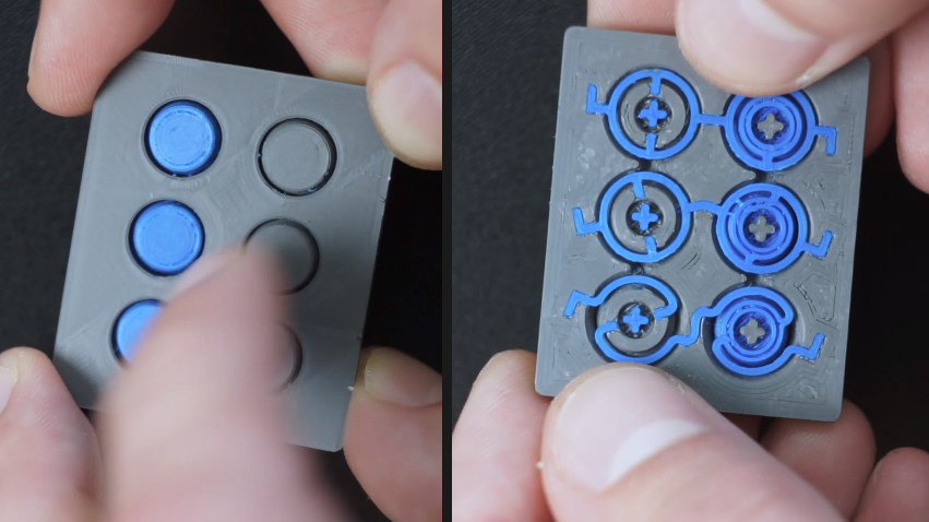 Since the voltage on all printer electronics is the same everywhere, the only thing that can be changed is the current on the motor. More precisely, it should be said the maximum current that the driver will supply to the motors. To change this limit, you need to climb inside the case and find the printer board. On it you will see the printer driver. We are interested in a small potentiometer on the driver itself (in the picture below it is indicated as a tuning resistor).
Example of potentiometer location on driver
For adjustment, you will need a voltmeter and a small Phillips or flathead screwdriver. Before proceeding further, it is necessary to calculate the maximum current supplied to the motors. Different formulas are used for different drivers, the most popular ones will be listed in the table below:
| Driver name | Formula | Explanations |
| A4988 | Vref = Imax * 1. | To understand which formula to use, you need to find a resistor with the signature R100 or R050 on the driver. They are located next to the driver chip. |
| DRV8825 | Vref = Imax / 2 | |
| LV8729 | Vref = Imax / 2 | |
| TMC2208 TMC2100 TMC2130 | Vref = Imax * 1.41 | One formula for all drivers |
 25 for R100
 The value of the maximum current (Imax) depends on the motor controlled by the driver. This can be found in the engine specification or on the sticker on it. The following are the currents for the most popular motor models:
17HS4401 - current 1.7 A
17HS8401 - current 1.8 A
17HS4402 - current 1.3 A
Substituting the value into the formula, we get the Vref value for the maximum current supplied to the motor.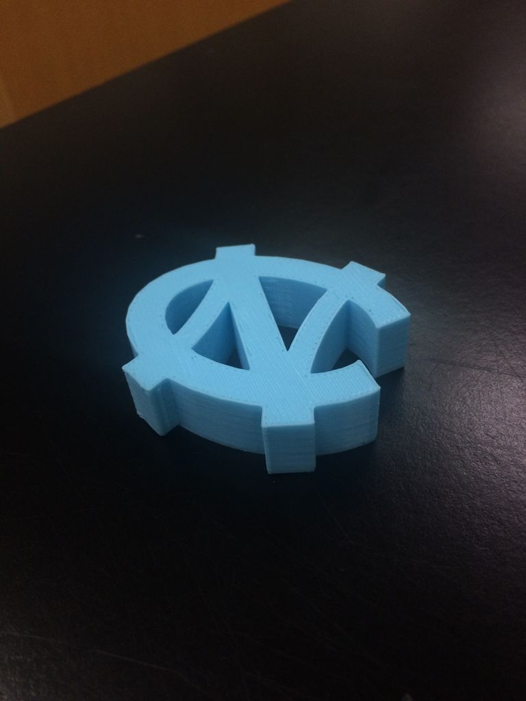 But at this value, the engine will get very hot, so the resulting Vref value must be multiplied by 0.7. For example, for a motor with a maximum current of 1.5 A and a TMC 2208 driver:
Vref=1.5*1.41*0.7=1.48V
Now the resulting value can be used when configuring on the printer itself. To do this, disconnect the wires going to the motors, turn on the printer and place one voltmeter probe in the center of the trimmer, and the second probe to the negative terminal on the power supply (you can also use the negative terminal on the printer board and the contact on the driver, labeled as GND). You will see some value on the voltmeter screen. Turn the trimmer clockwise to decrease the Vref value and counterclockwise to increase it.
Attention: you should not specify a Vref value higher than the maximum calculated for your engine! Otherwise, the engine will soon break down!
Once you have adjusted the value on the drivers, you can turn off the power to the printer, connect the motor wires, and put the case back together. This completes the driver setup.
Motor steps
When setting up motor steps, you will need a ruler. For convenience, you can use the program Repetier-Host. The adjustment for each of the three axes occurs according to the same algorithm:
-
Set the caret to zero coordinates (Autohome or G28)
-
Move the carriage some distance
-
We measure how far the carriage has traveled
-
We calculate the correct number of steps per millimeter using the formula:
True steps per millimeter = current steps per millimeter * reported distance / distance traveled
For example, if the printer was set to 100 steps/mm, we tell the printer to move 80mm and the printer travels 87.5mm. Then the correct steps per millimeter would be 100 * 80 / 87.5 = 91.42 steps/mm. For the convenience of measurements, you can fix a ruler on the table, and a thin object, such as a needle or pin, on the carriage. Then it will be possible to accurately measure the distance traveled. The extruder uses a partially different algorithm to measure distance:
-
Inserting plastic into the extruder
-
Cut it right at the outlet
-
We give the printer a command to stretch the plastic a certain distance (at least 100 millimeters)
-
Cutting plastic again
-
We measure the length of the resulting piece of plastic
-
We use the formula from the previous algorithm
Next, the settings data must be inserted into the firmware in the line:
#define DEFAULT_AXIS_STEPS_PER_UNIT {X,Y,Z,E0}
X,Y,Z and E0 should be replaced by the steps per millimeter for each of the axes, respectively. Otherwise, you need to insert this line into the initial GCODE:
M92 Ennn Xnnn Ynnn Znnn
Instead of nnn in each of the parameters, you must substitute the steps per millimeter for each axis.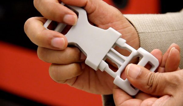 If you want to adjust the steps only for not all axes, then you can remove unnecessary parameters.
Acceleration
This parameter is responsible for the rate of change of speed. That is, how fast the printer will change its speed. This affects the nature of the movement of the hot end relative to the table. If the acceleration is too small, then the printer will print slowly, if it is too large, then the outer surface of the model will have visual defects: fading waves will be visible near each of the corners, as in the picture below.
To set up acceleration, you need to follow simple steps:
-
Cut a model of a standard test cube with a wall thickness equal to one nozzle diameter, without filling and top layers, bottom 2-3 layers;
-
Open GCODE file in notepad;
-
Find the G28 command at the very beginning and insert the line data after it:
M201 X5000 Y5000
M204 P500 T500
-
Save the changes, print the model according to the received GCODE and note at what parameters P and T it was printed;
-
Open the same GCODE file and change the P and T values on the second line, adding 500 to each;
-
Repeat steps 4-5 at least 3 times;
As a result, you will get several test cubes, some of which will show waves at the corners. Choose the cube that is printed with the highest P and T parameters, but that no waves can be seen on it. The number in parameter P will be the desired acceleration value. To save this value, you need to find 2 lines in the firmware:
#define DEFAULT_MAX_ACCELERATION {X,Y,Z,E0}
#define DEFAULT_ACCELERATION {nnn}
Instead of X and Y, you should put an acceleration twice as high as found earlier. And instead of nnn, you need to put the acceleration value found earlier. Otherwise, you need to insert a line in the initial GCODE:
M204 Pnnn Tnnn
In the parameters P and T, you need to put the value of the found acceleration. After that, the acceleration setting can be considered complete.
Jerk
A jerk indicates the speed with which to start accelerating. It affects the model in a similar way as acceleration: it creates ripples around the corners of the model. But it also increases the protrusion of the corners if the jerk is too small.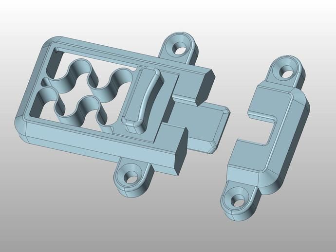 The jerk setting is also similar to the acceleration setting:
-
Cut a model of a standard test cube with a wall thickness equal to one nozzle diameter, without filling and top layers, bottom 2-3 layers.
-
Open GCODE file in notepad
-
Find the G28 command at the very beginning and insert the line data after it:
M205 X5 Y5
-
Save the changes, print the model according to the received GCODE and note at what X and Y parameters it was printed
-
Open the same GCODE file and change the X and Y values on the second line, adding 2 to each
-
Repeat steps 4-5 at least 3 times
As a result, you will get several cubes. Find a non-rippled cube printed at the highest X and Y settings. This will be the jerk value for your printer. To save them, you need to find the line in the firmware:
#define DEFAULT_XJERKnnn
#define DEFAULT_YJERKnnn
It is necessary to substitute the jerk values for the X and Y axes, respectively. Otherwise, you need to substitute the command in the starting GCODE:
M205
Instead of nnn, you need to substitute the jerk value found earlier. This completes the jerk setting.
Speed
In fact, there are many different speed parameters, the values \u200b\u200bof which vary greatly. Let's take a look at the main ones:
This parameter is responsible for moving the nozzle without extruding plastic. The value is in the range from 80 to 120 mm/s. Limited only by the maximum speed at which the motors can rotate. Does not affect the model
This speed is important because it indirectly affects the adhesion of the model to the table. Usually lies between 15 and 30 mm/s
-Print speed of inner walls
Usually set to about 60 mm/s, it only affects the strength of the model. Depends on the maximum amount of plastic that the extruder can push through the nozzle
-Speed of printing outer walls
Usually about half the printing speed of the inner walls (30 mm / s).