3D printed onahole
▷ 3d print onahole 【 STLFinder 】
Kitty Onahole/Fleshlight
thingiverse
... and resistance. The T-Shell is best printed in TPU or other flexible filaments. ( I just think it feels better.) Here are Links for some molds for fitting silicone sleeves: https://cults3d.com/de/modell-3d/naughties/onahole-sleeve-collection
setsuna onahole/sleevetoy/Fleshlight
thingiverse
... all parts for the print plate. Here are Links for some molds for fitting silicone sleeves: https://cults3d.com/de/modell-3d/naughties/onahole-sleeve-collection https://www.thingiverse.com/thing:5168136 I mirrored the design on my Cults3d uploads.
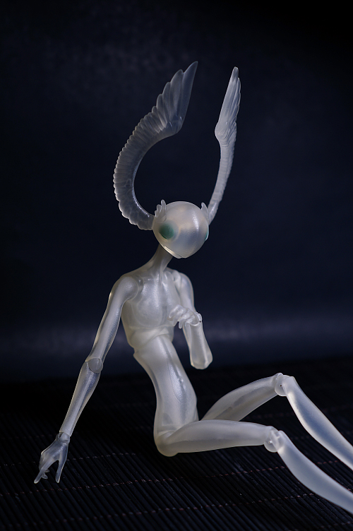
Projekt Melody onahole
thingiverse
... based on Projekt Melody (https://twitter.com/projektmelody) . Print the three bodys. The core you can print with a fexible fillament for easy removeal. Smoth them and bring use some rubberband to mound them. ... Use 00 Silicon to fill the hole.
Tifa onahole Tenga shell
thingiverse
... the sides to give it a Paizuri Feeling. And a Pantie cap is also included. Here are Links for some molds for fitting silicone sleeves: https://cults3d.com/de/modell-3d/naughties/onahole-sleeve-collection https://www.thingiverse.com/thing:5168136
T-Shell Basic onahole
thingiverse
. .. who wants something nutal. ...Instead of a single air hole this time there are 4 small holes to adjust the suction.
Here are Links to some molds for fitting silicone sleeves: https://cults3d.com/de/modell-3d/naughties/onahole-sleeve-collection
.. who wants something nutal. ...Instead of a single air hole this time there are 4 small holes to adjust the suction.
Here are Links to some molds for fitting silicone sleeves: https://cults3d.com/de/modell-3d/naughties/onahole-sleeve-collection
T-Shell FL onahole
thingiverse
... who wants something neutral. ...I add three ending caps, which I didn't test jet. This design works with my sleeve. Here are Links to some molds for fitting silicone sleeves: https://cults3d.com/de/modell-3d/naughties/onahole-sleeve-collection
Space Hunter Onahole Shell
thingiverse
... Looks like a space Bounty hunter. The shell is tighter than the original.
Here are Links for some molds for fitting silicone sleeves: https://cults3d.com/de/modell-3d/naughties/onahole-sleeve-collection https://www.thingiverse.com/thing:5168136
The shell is tighter than the original.
Here are Links for some molds for fitting silicone sleeves: https://cults3d.com/de/modell-3d/naughties/onahole-sleeve-collection https://www.thingiverse.com/thing:5168136
Meidri onahole Tenga Shell
thingiverse
... reviewers. The cap I added has a design that should resemble tights. Here are Links for some molds for fitting silicone sleeves: https://cults3d.com/de/modell-3d/naughties/onahole-sleeve-collection https://www.thingiverse.com/thing:5168136
Onahole Mold "Slime Can"
thingiverse
This is a Mold For an Onahole\Mastubator. ...The Desing of the Core was inpierd by a Slime Monstergirl. Smooth and wet.
Print the Shell twice and the core once. Smoth them and bring use some rubberband to mound them. ...Use 00 Silicon to fill the hole.
Smooth and wet.
Print the Shell twice and the core once. Smoth them and bring use some rubberband to mound them. ...Use 00 Silicon to fill the hole.
onahole sleeve collection
thingiverse
you need to print one 2 shells and the core you like. I will recommend the T-shell for every core if I designed a matching one. Classic shell ... like my slime can without the picture or text shell1... is for use with T-shell's 1. 3-way...
RUBY ROSE ONAHOLE
thingiverse
You need to print both shells and the core, fit them together and seal the mold. I use hot glue, but there are better ways like sealing clay or silicone. Fill the mold with low tensile Silicone like Ecoflex. If you freeze the filled mold, the...
NAMI ONAHOLE / MALE MASTURBATOR
thingiverse
You need to print both shells and the core, fit them together and seal the mold. I use hot glue, but there are better ways like sealing clay or silicone. Fill the mold with low tensile Silicone like Ecoflex. If you freeze the filled mold, the...
Aspholo T-shell Onahole/Fleshlight
thingiverse
... printed in TPU or other flexible filaments. ( I just think it feels better.) Here are Links for some molds for fitting silicone sleeves: https://cults3d. com/de/modell-3d/naughties/onahole-sleeve-collection https://www.thingiverse.com/thing:5168136
Aloe Onahole / Fleshlight Ishuzoku Reviewers
thingiverse
You need to print both shells and the core, fit them together and seal the mold. I use hot glue, but there are better ways like sealing clay or silicone. Fill the mold with low tensile Silicone like Ecoflex. If you freeze the filled mold, the...
3d print
grabcad
projects deigned for 3d printing
3d print
thingiverse
3d
3d print
thingiverse
Print 3d
grabcad
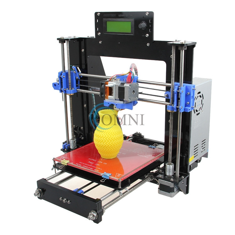
New to 3D printing? . ..Already have a printer and want to build another one?I SHARE MY OWN MODEL WITH YOU
3d print
thingiverse
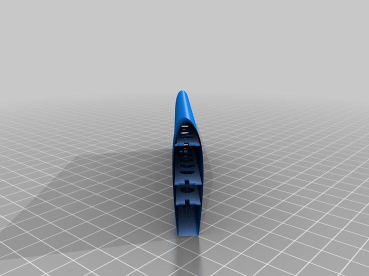
I created a design to be printed with a 3d printer on google sketch up. It did not come out as well as i would've liked but the design was well made. Instructions I first used the rectangle tool to...
3D Print
grabcad
Prototype 2 Design to be printed
Ring 3D print model 3D print model 3D print model 3D print 3D print model
cgtrader
Ring 3D print model 3D print model 3D print model 3D print model
Ring 3D print model 3D print model 3D print model 3D print model 3D print model
cgtrader
Ring 3D print model 3D print model 3D print model 3D print model
Woman Ring 3D print model 3D print model 3D print model 3D print 3D print model
cgtrader
Woman Ring 3D print model 3D print model 3D print model 3D print model
RAINBOW PRINT 3D print model
cgtrader
RAinbow is print able 3d model. ...File format is OBJ, STL
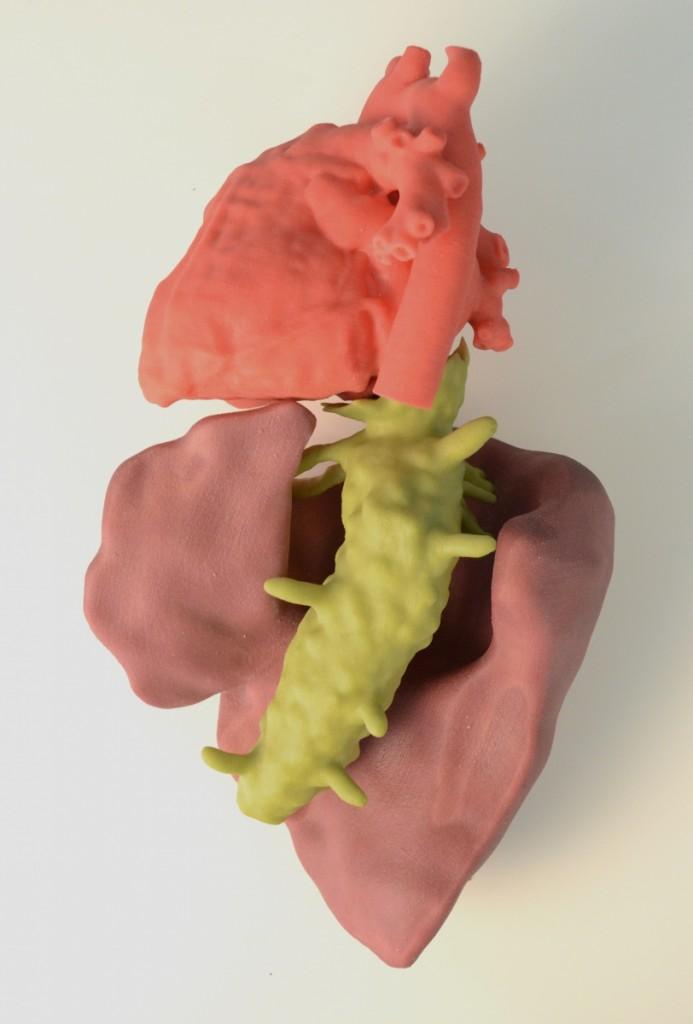
Heart Print 3D print model
cgtrader
Realistic Heart 3D model exported in multiple formats (obj, fbx, abc, stl, wrml, lwo) file format ready for print in 250 mm scale. The model is sculpted in 360° the Wrml file format keep the polypaint, for a beautiful colored print. You can find...
Print Free 3D print model
cgtrader
Print Create - Blender
Print object02 3D print model
cgtrader
This model is designed especially for testing the capabilities of 3d printers and comparing each other!Information ========== Length:120 mm Width:118.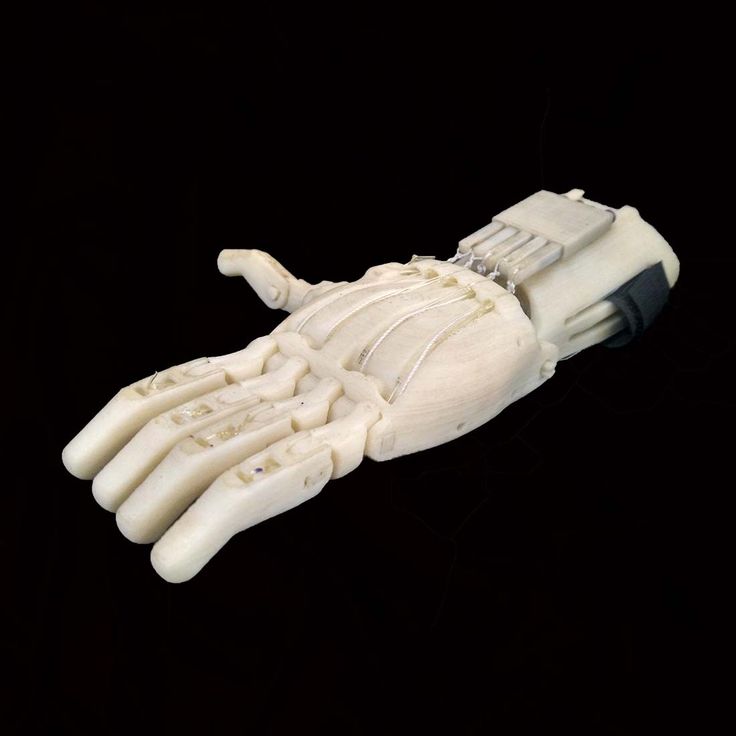 2 Triangles:1749518
Hunter 3d print 3D 3D print model
cgtrader
Model for 3D printing Contains formats OBG and STL The model contains 500к tris Link low poly game model https://www.cgtrader.com/3d-models/character/fantasy/creature-hunter
begemot 3d print 3D print model
cgtrader
Begemot, 3d print, 3d scan
3D Print Pot - 003 3D print model
cgtrader
3D Print Pot - 003
3d Printed Sex Toy - Etsy.
 de
deEtsy is no longer supporting older versions of your web browser in order to ensure that user data remains secure. Please update to the latest version.
Take full advantage of our site features by enabling JavaScript.
Find something memorable, join a community doing good.
(247 relevant results)
What is the actual size of the product after 3D printing?
05/10/2018 in 3D Modeling, Expert Blog, Instructions
In this article, we will consider the most common reasons for changing the final dimensions of manufactured products printed on a 3D printer. This article will be helpful for designers and inventors to understand how to design 3D models for 3D printing.
First, let's introduce some terminology. All deviations that occur in the technological process of 3D printing and related technologies, we will call “error”. Consider what types of errors are and delve into each of them.
- Extrusion width error.
- Approximation of radii depending on layer height.
- 3D printer extruder positioning accuracy.
- Inertial beats.
- Uncontrolled material shrinkage.
- First layer error.
- Porosity.
- Matching accuracy after printing details, splitting into components.
- Locations where support material is torn off.
- Thin wall roughness.
Extrusion width error.
Preparing a 3D model for 3D printing comes down to creating a so-called G-code. G-code is a computer code that sets the movement for all the electric motors of a 3D printer.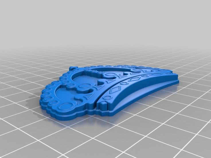 These motors include those responsible for moving the extruder (the 3D printer's 3D printed head). The movements and movements of the extruder are given by the trajectory, which is determined by the line. In preparation for 3D printing, the model is split along the Z axis into layers, determined by the selected layer height. The trajectory of the extruder is built based on the dimensions of these layers, and in the case of the layer perimeter, it describes the outer surface of the model, averaged along the Z axis. In turn, the extruder repeats the trajectory laid down in the G-code, namely the center of the nozzle. Ultimately, when designing models, it is necessary to take into account the fact that the nozzle itself has a hole diameter through which plastic is extruded. In simple terms, the nozzle radius is added to the size of the 3D model. When choosing a 3D printer, in terms of extrusion width error, the accuracy of the part will be higher on the one with a smaller diameter nozzle.
 And when designing three-dimensional models for 3D printing, it is necessary to lay a margin for model widening. I want to note that in other 3D printing technologies that use a laser or an illumination device, the width of the outer perimeter line depends on the focus, that is, on the thickness of the beam. As a rule, these parameters can be clarified with the manufacturer of the 3D printer or with Studia3D specialists.
Let's see how it works on the example of a 3D model that has a hole.
The figure shows the 3D model, rendering of the prepared G-code and the trajectory of the center of the extruder nozzle for the 7th layer of 3D printing. Select the perimeters of the holes and overlay the actual extrusion width on the trajectory (Highlighted in light green).
As you can see, the hole diameter is smaller. How much? On the nozzle radius on one side + the nozzle radius on the other. That is, when designing a hole, I need to lay a gap equal to the width of the nozzle.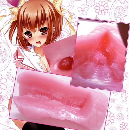 The same goes for all other cars. The smaller the nozzle size, the closer to the nominal dimensions the part will be. At the same time, printing with a nozzle of a smaller diameter will cost more. This is due to performance. Through a larger nozzle, more plastic comes out per unit time, which affects the speed of printing. The operating time of the printer, as well as the amount of material, affects the cost of obtaining the product.
Approximation of radii depending on layer height.
The specified layer height directly affects the accuracy of 3D printing. This is clearly expressed on the radii in the sections of the model along the vertical. Consider the part from the previous paragraph, positioning it on the edge in the 3D printer chamber.
As you can see in the figure, the quality of the hole depends on the selected layer height. The lower the layer height, the better the detail. In this case, it is worth considering the time of 3D printing. As the layer height increases, the print time decreases by reducing the total length of the trajectory described by the extruder. Accordingly, the price of the part is reduced, because. The operating time of a 3D printer directly affects the cost of 3D printing.
3D printer extruder positioning accuracy.
This parameter determines the accuracy of repetition by the center of the extruder nozzle of the trajectory specified in the G-code. In other words, this parameter characterizes the maximum possible deviation of the center of the extruder nozzle from the trajectory during printing. This parameter is specified by the 3D printer manufacturer for a specific printer model. But it should be noted that this parameter corresponds to the manufacturer's recommended 3D printing speed. In turn, Studia3D specialists, when preparing the G-code, reduce the influence of this parameter to a minimum, but do not exclude it at all. In addition to speed, this parameter is affected by the rigidity of the 3D printer and the extruder drive system.
Inertial beats.
As a special case of positioning accuracy, we single out inertial beats that occur during 3D printing as a separate point. This parameter is affected by the same positions that were described in the previous paragraph, however, this error is reduced in a different way. This can be understood by studying the moment at which the influence of this error on the print quality arises - a sharp change in the direction of the extruder's motion vector. When the electric motors, together with the drive system, abruptly change the direction of the trajectory, the print head, which has some characteristic weight, continues to move in the previous direction by inertia. As a result, dynamic damped oscillations occur, which negatively reflects the surface. The influence of this error is reduced in two ways. Decreasing the speed of printing the outer perimeter, which we use when printing all models without exception and is laid at the stage of preparing the G-code. The second method is laid down when designing the model: if possible, it is necessary to add mates to acute-angled faces in the model, which, when the part is positioned on the 3D printer platform, in sections parallel to the XY plane, will give sharp corners in the perimeters.
 As practice shows, a pairing of 2 mm is considered sufficient. We show with an example.
As you can see in the figure, by rounding the corner (by entering a fillet on the face), we minimized the influence of this error.
Uncontrolled material shrinkage.
This parameter has its effect, as a rule, in the case of 3D printing of large objects. Large - this means more than 30% of the maximum size of the 3D printer camera along any of the coordinate axes. Most often, this error manifests itself in interlayer adhesion and a decrease in dimensions in planes parallel to XY.
Our observations have shown an approximate shrinkage for some of the most common materials in relation to cross-sectional dimensions parallel to the coordinate axes.
ABS: XY ≈ 5%; Z ≈ 1%
PLA: XY ≈ 2%; Z ≈ 0.5%
Polypropylene: XY ≈ 7%; by Z ≈ 10%
First layer error.
The G-code preparation program considers the 3D printer platform to be absolutely parallel to the XY plane, however, in practice, platform calibration also has its own error.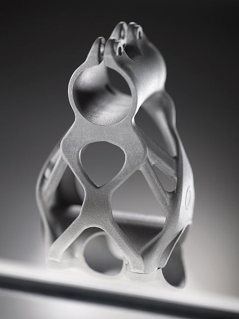 In Studia3D, the norm for the difference in thickness of the first layer is:
Δ=0.1 mm from a layer height of 0.2 mm
Δ=0.05 mm from a layer height of up to 0.2 mm
Porosity.
Porosity in the case of 3D printing is usually discussed only in the case of the percentage of filling of internal floors up to 100%. However, when printing with 100% infill, the porosity does not go anywhere.
This can be clearly seen by examining the gap in the workpiece through a microscope to determine the strength characteristics.
If the model is not included in the printable area of the 3D printer, it is split into components. In the best case, grooves are provided for the most accurate assembly. You need to understand that the assembly of the model from the components also affects the accuracy of the overall design. This accuracy is very difficult to assess. We accept deviations from the given model of the order of + - 2%. To fix the joint, we almost never use glue, but use a special chemical solution. Ultimately, the parts are not glued, but soldered, only not by thermal melting of the material, but by chemical. As for the adhesion strength: it is higher than the adhesion between layers. In simple terms, if you throw such a part against a wall, it will break, but first of all not at the joints.
Locations where support material has been torn off.
This item applies to mechanically removed supports. Since the material of the support and the material of the main part consist of the same material, they are simply soldered together under the influence of temperature. When such supports are torn off, traces, threads, chips, etc. remain.
To minimize this error, it is necessary to order 3D printing with soluble supports. Due to the expensive soluble support material, the cost of 3D printing also increases significantly. Accuracy, like beauty, requires sacrifice.
Thin wall roughness.
When preparing a G-code in standard form, the program strives to make your part as strong as possible. This is bad only in one case, when the product has thin-walled elements. When constructing a trajectory, we set the minimum wall thickness inside which the infill will be built. As a rule, this thickness is equal to the 3rd nozzle diameter. But in cases where there are places where the thickness is less than the thickness of the outer wall, when constructing the trajectory, the program will draw one perimeter on each side, and fill the void between them. Due to the fact that filling will occur at a distance of 1 to 2 nozzle diameters, the extruder will begin to vibrate, inertial beat will begin (see point inertial runout ). The more this distance is reduced to 1 nozzle diameter, the faster the near-resonant frequency occurs. All this negatively affects the appearance of this wall, since the vibration is transmitted to the adjacent material. Let's look clearly.
To minimize this error, it is necessary to design the part in such a way that the wall thickness is a multiple of the nozzle diameter.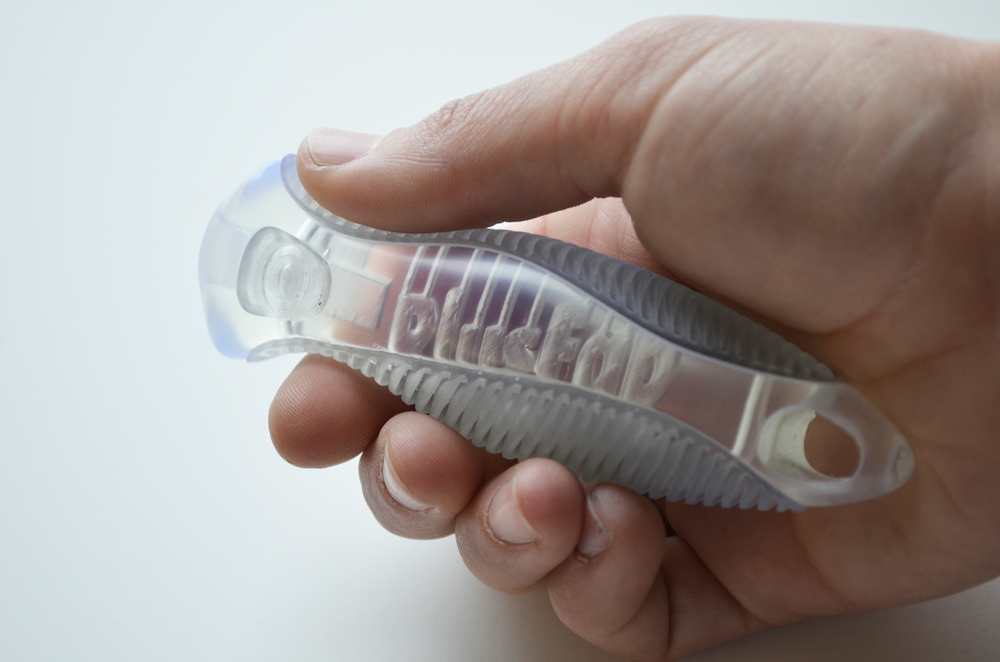 Face difference!
Output.
In conclusion, I want to note that when designing three-dimensional models for 3D printing, it is necessary to take into account the totality of all factors affecting the accuracy of products, and not consider any particular one. The Studia3D team works every day to ensure that the 3D printing process is completely predictable and controllable, however, like any kind of production, 3D printing has its own precision. There are no ideal sizes. Therefore, we are very pleased if, in addition to three-dimensional models, a working drawing of the product is provided, where all fits, tolerances, roughness, etc. are indicated. Only in this case we can choose the technology, properly prepare the G-code and guarantee the quality laid down by the designer. In other cases, before starting a batch, it is necessary to make “sighting” seals, having examined and selected the necessary parameters.
Prototyping workshop - 3D printing, milling, scanning, electronics development
Rounded corners problem during printing
It is clear that due to the round shape of the nozzle of a 3D printer, when printing parts, it is impossible to make their corners perfectly sharp. In addition, when printing square corners, depending on the speed, additional plastic build-up may occur due to the print head slowing down when passing the corner of the part. For example, when the head slows down, the pressure of the nozzle increases, as a result of which a layer of plastic is squeezed out a little thicker than if a normal straight surface was being printed.
This effect is noticeable in the photo below - although the corner of the part was perfectly square in CAD, the printer could not print such a corner. Even worse in the photo looks a slight influx of plastic from above.
It seems that in most cases a rounded and slightly enlarged corner will not be a problem, but what if you are trying to print a square part that should fit into a square hole, such as a lid?
If you want to avoid this problem, then it is enough to make the corners a little rounded in advance, at the model development stage.
Printing of finished assemblies
Models are built layer by layer on a 3D printer.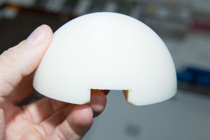 Perhaps this fact can be used for some trick. So, for example, in some cases, a 3D printer can print a product consisting of different parts, immediately assembled, and not print each part separately, in order to then assemble the product itself from them.
When developing models of this type, it is necessary to make sure that the various parts of this model cannot stick to each other, as well as move relative to each other. This situation can happen when you have one part printed directly on top of another part, and this can be a big problem when printing because the filament extruded directly in the air will bend unpredictably, which will lead to sagging of the top of the product, due to which it can stick to the bottom. To avoid this type of problem, it is very important to leave a sufficient gap between the parts of the printed product, and the width of this gap for each case will be individual.
For example, if the overhang of the part is very small, say 10mm in diameter, then you can set the gap height to 0. 5mm. Well, if the overhanging part is long, or has a complex geometric shape, then, accordingly, its sagging will be much greater and, therefore, it is necessary to proportionally increase the height of the gap. The easiest way to figure out how much clearance to set is to try and see how the problematic part of the model will print. By creating small test models, you can spend much less plastic time than if you printed the entire product every time you try to eliminate errors.
The illustrations below show an example of a composite product printed as a single piece. This is a folding dust filter.
Top image - complete filter model
The lower image is a section of the hinge (loop) of the filter
As you can see, the hinge (hinge) has a protrusion of about 45 degrees, which allows the 3D printer to easily print the part, as well as avoid the sagging problem that would lead to the parts of the hinge (hinge) sticking together.
When you work in 2D space, with the X-Y coordinate plane, you can create parts of models with fairly tight tolerances. So, for our part, the minimum gap is only 0.2 mm. But there is another problem that you may encounter - this is the so-called stretching of plastic threads between adjacent parts, which again can lead to gluing parts of the product.
You can get more information about this problem and how to fix it here.
Of course, you can print not only connected parts of one product. So, as one very common example, you can bring a whistle that has a ball inside, and this ball is printed from the very beginning along with the whistle itself. At the end of the press, the ball is pulled out of the whistle, but in such a way that it remains inside, due to this it can sound freely.
The cost of printing does not depend on the complexity of the form
By this heading, we mean that the printer doesn't care whether it prints a cube or an intricate set of shapes. There is no doubt that printing a simple cube does not require a large number of nozzle movements, so the print time will be lower compared to complex models. But if you omit this fact, printing complex forms is definitely beneficial, because the cost of printing does not actually depend on the complexity of the form.
A classic example of this idea is commercial aircraft parts such as the bracket in the picture below. We can optimize its shape by not cutting it out of a solid piece of metal, but printing it out of plastic on a 3D printer.
Image taken from Airbus.com
We believe that with traditional manufacturing tools, we will never be able to create perfect voids in the model, unless we can make something similar to such voids using drilling / milling. But, when using 3D printing, we have the possibility of placing a cavity under a thin layer of plastic, which will further increase the strength of the model and reduce the mass of parts and consumables.
Connection of large parts
Even with 3D printers such as the Ultimaker and Ultimaker2, which have fairly large printable areas, there may be a situation where you need to print a part larger than the printer's printable area. To get out of the situation - we will divide the model into several parts, print the parts separately, and then connect them together. The easiest way to connect is to glue the parts together. Obviously, this way we will achieve the desired result, but do not forget that we are using a 3D printer, so why not get creative?
But let's go back to gluing for a second. For convenience and smooth gluing of parts, as well as to facilitate this process, you can add holes and round pegs to them on the corresponding sides of the models. As a rule, this is enough to be sure that the parts are connected correctly and, while the glue dries, not only places will not move, but also relative to each other.
If you need to glue a rather narrow part to a wide one, then in this case you can print special guides that will fix the glued part in relation to other parts of the part. Make a couple of mounting holes in the parts to be joined, then fasten the guides, leaving a small gap so that when gluing the parts, the location of the parts remains correct.
If you don't like the way parts are glued together, you can peep a few ways from carpenters. For example, the dovetail joint is used by woodworkers and there is no reason not to use it in 3D printing.
This complexity of design does not complicate the manufacture of parts, you can also leave the connection temporary or fix the parts together with glue.
Assemble to print all parts in one go
It is always tempting to print a large part at once, but as often happens, fixing its first layer on the platform and then printing the whole part evenly is quite problematic. Therefore, do not be afraid to print several details at once. Here are a couple of reasons why it's best to print some parts piecemeal: first, you can get rid of supports, which, let's face it, take a very long time to remove; secondly, thanks to this method, the strength of the part can be significantly increased.
Let's look at the first reason. Surely you have encountered the difficulty of printing protruding elements of parts. Of course, the best option when printing overhangs is to eliminate them at the stage of product modeling. But, if this is not possible, then you can divide the model into several parts and arrange them in such a way that the protrusions are no longer a problem.
The figure shows an example of a part that is difficult to print at one time, regardless of its printing position. For printing, you will have to use a large number of supports, which will lead to high material consumption. But, if you break the model into two parts, then printing will be much simpler, and instead of removing the supports, it will be enough for you to connect them with glue. Pay attention to the added chamfers at the hole and the peg - this is done to simplify the connection of parts of the part.
Strength is another reason for splitting a part into several parts. If you need to print a narrow cylinder perpendicular to the substrate, then it makes sense to print it separately, lying on the table, this will give it strength, since the printing direction will be along the longitudinal axis of the cylinder.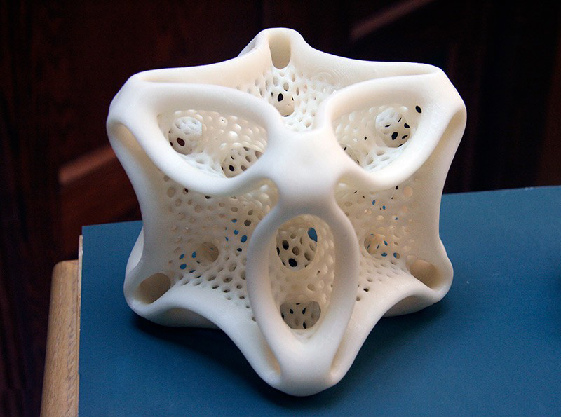
How to make the fixing of perpendicular parts of the part stronger
Suppose you want to print a vertical cylinder on a cuboid. At the junction of the figures there will be too sharp a transition, due to which the part may break if you press on the cylinder. You can strengthen the part by adding a ring of the appropriate height to the model at the junction of the figures (see the figure below).
Addition of metal elements to increase the strength of plastic parts
Currently, the vast majority of 3D printers print with various types of plastic, but compared to plastic, metal has much more durable characteristics. Why not try to combine the best of these technologies? We can use the print pause function to add iron parts to parts and then resume printing. A great example is to insert metal nuts into the right places on one part, then to screw it with screws to another part.
Make sure you have enough material around the nut, otherwise the nut will play when you tighten the screw. Strengthening the area around the nut can either be done by printing a few extra lines around the perimeter or by tricking the slicer into 100% infill where needed.
How to print horizontal holes
When printing horizontal holes, the top edge overhangs and creates an arc. This means that the horizontal holes will be slightly flattened at the top and will shrink in size. There are several ways in which you can align the holes.
The first approach is to reshape the hole during the modeling phase, making the hole look more like a water drop. This makes the printing process easier as there is a slight gap for the plastic to sag during printing.
You may not like the look of the resulting hole. In this case, there is another way that you can use. It consists in creating a thin support membrane that supports the edge of the hole in one of the places.
If you don't care about the appearance of the hole and are going to use it for practical purposes, you can also experiment with different hole shapes.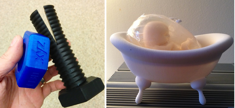 How about a triangle or square with one of the corners pointing up? Basically this idea is useful for small holes. Remember to leave clearance around the hole if a screw will be inserted into it.
Increased strength due to 100% filling
3D printer uses different software. And some programs do not allow you to set multiple plastic fill options during printing. In such a case, to increase the strength of the part, you can increase the amount of plastic fed or the number of perimeter walks for the entire part.
But you can use one trick to overcome this shortcoming and create a model that prints more plastic in the areas where you need it. The method consists in adding a group of cylinders in the place where more strength is needed. This will force the program to print many cylinder print lines, which will fill the area more densely.
The illustration below shows an example of this trick. It shows a product in the form of a box with a little excessive filling. In this case, cylinders with a diameter of 0.5 mm were used at a distance of 1 mm from each other. For each specific situation, you will have to experiment with the dimensions of the cylinders and the distances between them in order to find the optimal values. Cylinders must necessarily cross the upper and lower planes, otherwise unpleasant situations may arise during printing. Play with the settings (for example, in Cura's "Fix horrible" slicer) so that the slicer doesn't throw cylinders out of its calculation. In any case, in the program, before printing, it is necessary to check the appearance of the layers.
Below is another example where we added many small holes around one large mounting hole. It turned out not one hundred percent filling, but, nevertheless, unlike the hole of the same size on the right, it is much stronger.
Round corners to reduce distortion
Curvature occurs more frequently at sharp corners, which are areas of increased stress and material stress during printing.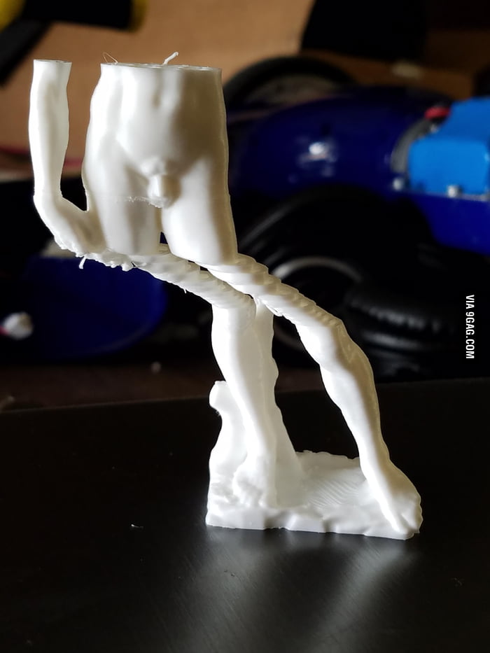 By rounding the corners, you will slightly reduce this effect.
Strength-oriented optimization
To get an idea of how durable your printed parts are, try imagining they are made of wood. If you've ever chopped wood, then imagine that it's much easier to cut along the fibers than across.
Think about your printed parts in this way. Position and design them to be as solid as possible. If you have a complex part with sticking out parts, then you can break it into several parts, and then assemble it after printing. By doing this, you can not only save time, but also get rid of supports.
Pay attention to plastic shrinkage after cooling
We have already noted that parts after printing tend to decrease in volume when cooled. This is especially problematic for small holes. To avoid this, you need to scale the holes to compensate for shrinkage. Over time, you will gain experience, and you will automatically understand how much to scale an element to compensate for compression.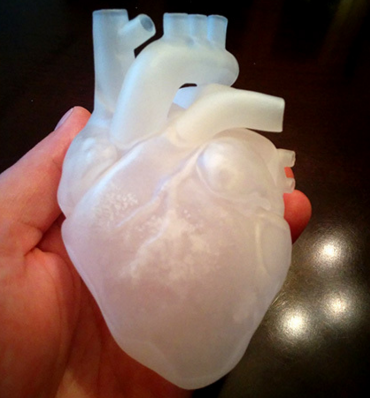
It is worth noting that if your model has few polygons, then this will also lead to a decrease in holes. Since the hole is a series of straight lines, the low number of polygons means that the lines will run over the diameter of the hole. As a rule, this situation will not lead to a strong decrease in size, but it is still worth remembering.
For a better understanding of the downsizing problem, you can print a model with different hole diameters and compare which size is in the computer model and which one is printed. This will help you better scale the holes while modeling.
Model closure, what is it and why is it important?
A model that is not "closed" cannot exist in the real world. This means that the model has edges or vertices floating in space, areas of zero thickness. This also applies to "permeable" models, which, for example, have holes in the form of a grid.
It is important to correct these errors as they can confuse your slicer and lead to unpredictable print paths. There is a free online service for fixing such problems, you can find it here.
It may also be worth trying to change the export settings in your CAD to avoid errors. A setting such as the resolution of the exported model may solve the problem.
Wall thickness
If your model contains thin walls, it might be a good idea to make them multiples of your nozzle width (0.4mm for UltiMaker2). If you make the wall thinner than the nozzle width, it's possible that your program will remove it entirely from the model if it realizes it can't properly print such a thin wall.
45 degree rule
When designing the model, you should try to keep the angles of the protrusions to a maximum of 45 degrees. The printer is capable of printing angles greater than this angle, but if you are aiming for good surface quality, then reduce the angle as much as you can. The steeper the angle, the worse the print quality.
The illustration shows how models could be designed for the best possible 3D printing experience. The first image shows that the top of the model has an obvious overhang that must be maintained if the goal is to print correctly. Of course, it is possible to print the part using supports, a little more about this will be written below.
The image in the middle shows a 45 degree overhang angle change for easy printing. But, of course, this is not always possible. Alternatively, this part should be used as a belt roller, which should be in the middle and have stops.
In the third version, we split the model into two parts, and added a pin and a hole so that the parts can be glued together after printing. This approach keeps the edges straight.
Create your own supports instead of automatically generated ones
Whenever you have a part of a model hanging in the air, you need print supports. They allow you to print parts that are usually impossible to print just like that. The bad thing is that after removal, they leave scratches on the surface.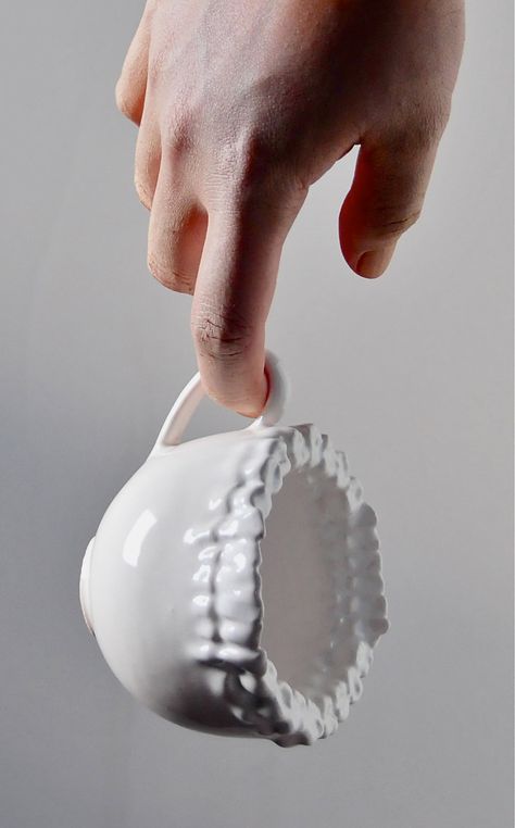
Lifts can be generated automatically or you can make them yourself. Most printing software makes supports automatically and they do the job, but these supports are difficult to remove and leave scratches on the surface. An alternative would be to use a separate program, such as Meshmixer (link). While the built-in generators create a "block" of support structures under the overhanging part of the model, Meshmixer instead tries to use small columns of material for support. An excellent guide to using this program can be found here.
But the best way is to create supports manually when developing the model. Humans are still smarter than computers in this area and can be a little more resourceful about how best to build support. So you can save printing time and plastic. You can also prevent and hide any scratches. The picture below shows the overhang and two supports in red.
This image shows automatically generated supports. Note that the default settings have been applied. But you can tweak some settings to improve the result a bit. In our example, ironically, the automatically generated support itself requires support.
In the image above, the homemade support (highlighted in red) nicely supports the protrusion and we can take advantage of the 3-D printer's properties to apply material at small intervals. The printer will start printing on the perimeters that are fully supported by the custom supports. These perimeter lines will form the base for the plastic that will be applied to the rest of the gaps.
When creating the support, it is important that you leave a small air gap between the support and the actual model so that the support does not blend into the rest. What the gap should be depends on the height of the layer and how the model looks. As a rule, a gap of 0.15 mm is used.
Create lintels instead of a steep canopy if possible
As mentioned above, supports leave scratches on the surface. They also waste a lot of time and plastic. Therefore, you should try not to use them.
The printer cannot print what is in the air, but it can print small bridges in the air. We call this effect the "bridge" effect, as it essentially stretches a strand of plastic between two bases, similar to the cables on suspension bridges. On this page there are a large number of different models printed on different types of printers that use jumpers.
Using the bridge effect is very useful when printing models, such as a model of a house with open windows. A short span over an open window can be easily bridged, saving both time and plastic.
This does not mean that the bridge effect is miraculous, of course, it has its own problems. For example, you can't bridge long gaps with bridges and still expect the bottom surface to look perfect, as sagging plastic threads are inevitable in this case. Short spans, however, may not be a problem. To reduce slack, it's best to slow down the print speed and make sure the extruded filament cooler is working so well that it becomes stiff as quickly as possible.
This image shows a typical case where a "bridge" might be a much better choice if the design allows it. A gently sloping overhang is likely to have very poor surface quality on the underside. By making a straight bridge, you can improve the print quality. If you want a flat overhang, you can of course use a support to print it, but again, the surface will be rough.
The illustrations below are printed models illustrating the quality of the surfaces.
Slopes and stepped slopes
Since the printer creates an object by superimposing one layer on another with some offset, the "ladder" will be visible after printing, and not a smooth curve. If you are a gamer, then this “aliasing” effect is most likely familiar to you, it looks similar.
You won't notice this effect on a vertical surface as the layers will be on top of each other. As the angle increases, the effect will become more and more pronounced. You can soften it by lowering the layer height. The illustration below shows this.
As you can see, thinner layers can render the true shape much better. Also notice how much worse the top of the object looks compared to the bottom layers. As the angle increases, the rings become more visible.
Currently, some printing software (including cura) does not allow you to select (or automatically detect) areas that need thinner layers to reproduce the detail in the best possible way. So if you find that you need extra resolution then print the entire object with a lower layer height. Of course, this will increase the print time a lot.
We suggest you use the Slic3r program. This slicer will allow you to select different layer heights for different print areas to get the best quality and print speed.
But, of course, there are other alternatives, such as trying to design your models in such a way that their slopes are not very smooth and streamlined.
Plastic shrinkage
Unfortunately, this is only a small part of all the problems that you will encounter if you are trying to create parts with very precise dimensions. The degree of shrinkage depends on many different parameters, such as: type of plastic, shape of the part, cooling, heating / no heating of the base, etc.
In short, there are many nuances. This problem is not unique to FDM printers, it also affects injection molding, for example. The molding also needs to compensate for how the plastic will shrink in angles and dimensions.
So how do we deal with this? We are experimenting. Consider an example - usually vertical holes are smaller than expected. The problem is exacerbated if these holes are small. So if you want the hole to fit an M3 screw when printed, you have to make the hole in the CAD bigger than it needs to be. If you want the screw to sit quietly, you can try, for example, a diameter of about 3.4 mm. You can print part of the part, measure the result, and then modify the CAD model with the desired hole dimensions. This is not an exact algorithm of actions, but with experience you will automatically determine how to compensate for shrinkage in order to achieve a good result.
You must be surprised that vertical holes are especially troublesome to print? The answer is simple - when you print a hole, the plastic sags down into the void below it (obviously), since the plastic behaves almost like rubber (when heated), which shrinks.
In addition to shrinkage, as you can see, the first layer is usually printed flattened, resulting in an even smaller hole. The use of a chamfer will help to cope with this problem.
Use chamfer to print a quality bottom edge
The first layer is usually pressed against the platform more strongly than subsequent layers. This is to ensure that the first layer adheres better to the platform, and as a result, the lower surface is smooth, like a mirror. The downside is that the dimensions of the first layer are larger (or smaller depending on how you look at it). You can negate this effect by adding a fillet to the bottom of your model. Depending on the height of the first layer and the height of the layer for the rest of the print, rounding can be from 0.4mm to 1mm. The gap will give the plastic some room to expand.
It is important that you can use a chamfer instead of a fillet. Rounding will create a serious overhang that will look ugly. The chamfer, as a rule, is done at 45 degrees, the printer will be able to print it very beautifully.
If you still want a fillet on the bottom of the part, you can make a chamfer and make a fillet on the top. By doing so, the overhang will fail. The picture above shows the difference. Note that the red highlight is the overhang, which will be difficult to print compared to the slight 45 degree angle from the chamfer + fillet.
Trick to create a beautiful top
In addition to the information listed here, there is a very neat trick that was first introduced by Dreamworker on the Ultimaker forums.