3D printed molecular models
Molecular models for biochemistry, biotechnology to biomedical science
Based in part on Wrapp et al Science 2020. The University of Texas at Austin
Molecular model showing structure of the 2019-nCoV Spike Glycoprotein with ACE2
Based in part on Wrapp et al Science 2020. The University of Texas at Austin
Molecular model showing structure of the 2019-nCoV Spike Glycoprotein with ACE2
Based in part on Wrapp et al Science 2020. The University of Texas at Austin
Molecular model showing structure of the 2019-nCoV Spike Glycoprotein with ACE2
Molecular Models in collaboration with Lee 3D, have been working with life-science researchers and scientists across the UK and beyond to bring molecular structures to life using colour 3D printing. We printed the SARS-Cov-2 spike trimer for Prof. Jason McLellan (University of Texas at Austin).
Copies of the model have been gifted to the vaccine development teams at Oxford University and Imperial College London. These models are hugely beneficial as communication aids in public outreach.
The SARS-CoV-2 spike protein is a key target for a vaccine against Covid-19. It is termed a ‘spike’ protein since dozens of copies of this molecule sit on the outside of each tiny corona virus; these give each virus a distinct spiky appearance – like a crown (or corona).
The spike protein is made of three protein chains (shown in red, green and blue on the model) that wind together to form a trimer. When a Covid-19 virus infects a human, the tip of each spike can interact with a human protein that is naturally present in the cell membrane of our respiratory epithelia – angiotensin-converting enzyme (ACE2).
The ACE2 molecule is shown in yellow and the magnets show how it can specifically attach to the spike trimer. When the spike binds to ACE2, this can lead to the virus binding and then infecting the human cell. The trimer is also covered in small sugar molecules called glycans and the biological function of these and their role in infection is still being studied.
The structure we have printed comes from cryo-EM data published by the group of Prof. Jason McLellan, University of Texas at Austin, in the journal Science in February 2020:
Wrapp et al, (2020), Cryo-EM structure of the 2019-nCoV spike in the prefusion conformation, Science, 367, 1260–1263
Jiang et al, (2016), Structures of a CRISPR-Cas9 R-loop complex primed for DNA cleavage, Science, 351, 867–871
Molecular Model showing structure of the CRISPR-Cas9 complex
Jiang et al, (2016), Structures of a CRISPR-Cas9 R-loop complex primed for DNA cleavage, Science, 351, 867–871
Molecular Model showing structure of the CRISPR-Cas9 complex
Jiang et al, (2016), Structures of a CRISPR-Cas9 R-loop complex primed for DNA cleavage, Science, 351, 867–871
Molecular Model showing structure of the CRISPR-Cas9 complex
This model, solved by Prof. Jennifer Doudna’s team at the University of California, Berkeley, shows the crystal structure of catalytically-active Streptococcus pyogenes CRISPR-Cas9 in complex with a single-guide RNA and a double-stranded viral DNA target.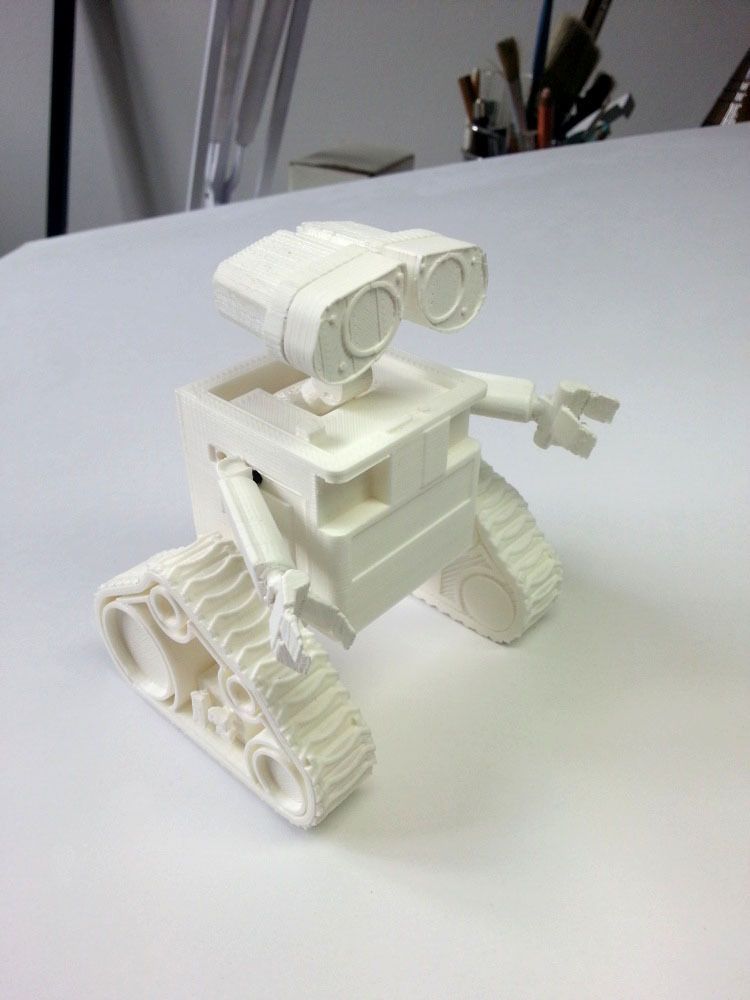 The complex is primed for DNA cleavage and shows how bacteria use a CRISPR-Cas nuclease to recognise and then degrade invading viral DNA – a form of bacterial immune system. This recognition is achieved with extraordinary specificity using a guide-RNA strand that directs the Cas9 enzyme to a specific DNA sequence. This property of being able to target, cut or change any DNA sequence with exquisite precision has led to the exciting and rapidly-expanding field of CRISPR-Cas gene-editing technologies.
The colourful hands-on model we have made is ideal for use in undergraduate and postgraduate lectures and practicals, allowing students to explore, measure and appreciate the close link between molecular structure and function. The model works well in any life science degree where gene-editing is taught: from genetics to biochemistry, biotechnology to biomedical science. The model is equally useful to researchers as a visual reference and hands-on demo in science communication and school/college outreach events.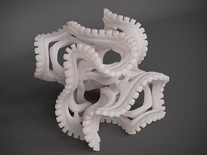
The 25 cm-long model sits on a mounting stand, from which it can be easily removed. We have used ten different colours to identify ten key features/domains of the complex. This visual key is to aid learning: the guide-RNA is in red, the DNA strands are in light and dark blue and the Cas9 enzyme domains are in seven further colours. We provide a list of each feature – and what it does – with the model. We have added optional labels (that are attached to the structure) to help students visually identify the various parts of the structure.
As the photos above show, there are three magnetically-detachable sections that help reveal where the separated DNA strands and guide-RNA are; how the nuclease active sites are positioned next to the DNA, and how Cas9 encircles the nucleic acids.
The structure we have printed comes from X-ray crystallography data (PDB code 5F9R) published by the group of Prof. Jennifer Doudna, UC-Berkeley, in the journal Science in February 2016:
Jiang et al, (2016), Structures of a CRISPR-Cas9 R-loop complex primed for DNA cleavage, Science, 351, 867–871
This molecular model was a collaboration with Prof. Thomas Meier at Imperial College London. It shows all twenty-six subunits that comprise a fully functioning plant ATP synthase. ATP synthases – found across all three kingdoms of life – act like molecular turbines and generate large numbers of high-energy ATP molecules for cell use. The machine operates by directing protons (H+ ions) from one side of a membrane (here, the chloroplast thylakoid membrane) to the other.
The model is coloured by subunit to aid understanding of how the motor works. It comprises two major complexes, a water soluble F1 complex and the membrane-embedded (Fo) complex. Functionally, the ATP synthase can be divided in a stationary part (called the stator) and rotary part (called the rotor). Protons enter the Fo motor by the stator a-subunit (pale blue+red), which directs them onto the c-ring rotor (wheat). On each of the 14 c-ring subunits is a glutamate residue (red spot) that conducts the protons round almost 360° to an exit point on the a-subunit. The continuous movement of this proton stream (shown in red) is converted into rotary motion. The c-ring is directly attached to a rotor shaft that comprises the epsilon (magenta), and gamma subunits (blue+yellow). So as the c-ring rotates, the attached shaft spins at the same rate.
The key feature of the model is that the Fo motor is free to rotate, providing a clear visual demonstration of how the top of the gamma subunit rotates deep within the stationary F1 head. The hexameric head is made from alternating alpha and beta subunits (dark and light green) and is held in place by the peripheral stalk, a scaffold of subunits made from the b-subunit (purple), b’-subunit (pink) and delta-subunit (orange). The ATP synthase rotation mechanism is fully reversible and can operate either in ATP synthesis mode (making ATP, using the proton-motive force), or in ATPase (hydrolysis) mode, to pump protons across the membranes and maintain the proton-motive force, depending on cell physiological conditions. The movie shows the ATP synthase operating in clockwise direction (when viewed from to of F1), which is in ATPase proton pumping direction.
The 20 cm-high model sits on a removable transparent frame, which fits into a base section. Using glossy colours to identify each of the 26 subunits and how they are positioned in relation to each other was a key part of the project brief. Also visible inside the alpha and beta headgroup are the ATP and ADP molecules, where ATP synthesis is occurring by the classic 3-stage binding-change mechanism.
The structure we have printed comes from cryo-EM data (PDB code 6FKF) and was published in the journal Science by the team of Alexander Hahn, Janet Vonck, Deryck Mills, Thomas Meier and Werner Kühlbrandt:
Hahn et al, (2018), Structure, mechanism and regulation of the chloroplast ATP synthase, Science, 360, eaat4318.
Structure of the F1Fo ATP Synthase
Structure of the F1Fo ATP Synthase
Structure of the F1Fo ATP Synthase
Structure of the F1Fo ATP Synthase
Structure of the F1Fo ATP Synthase
Structure of the F1Fo ATP Synthase
Oxyhaemoglobin
Breathe in! Human oxyhaemoglobin. This glossy model shows the four subunits of haemoglobin.
Oxyhaemoglobin
Four subunits of haemoglobin. The two alpha subunits are in white and black; the two beta subunits are in light and medium grey.
Oxyhaemoglobin
The haem group in each monomer subunit is in red and shows where an O2 molecule binds – four dioxygens per haemoglobin tetramer.
Oxyhaemoglobin
Cut-away model through the middle of haemoglobin to reveal the complex polypeptide chain folding inside the molecule.
COX-2 with aspirin molecules
How aspirin works: structure of the enzyme cyclooxygenase 2 (COX-2). COX-2, is a homodimer and in this model the subunits are coloured white and blue; the haem group in each subunit required for prostaglandin synthesis is shown in red.
COX-2 with aspirin molecules
COX-2, also known as prostaglandin h3 synthase, is inhibited by the anti-inflammatory drug aspirin. Aspirin molecules are shown to scale alongside. Model made for the Biochemical Society outreach team.
C.Csp231I
This 2 part magnetic model shows how the complex assembles.
C.Csp231I
Structure of the Restriction-Modification controller protein C.Csp231I.
C.Csp231I
This protein consists of two dimers (orange/yellow and light/dark blue) that interact to hold the DNA in a loop.
Nucleosome Fibre
Six models of the 50 nm nucleosome fibre. Each model represents a different theoretical inter-nucleosomal spacing; nucleosomes are shown as yellow and orange spheres.
Nucleosome Fibre
These images shows how useful physical models can be for inspecting and evaluating molecular structures.
Nucleosome Fibre
These images shows how useful physical models can be for inspecting and evaluating molecular structures.
3D Printing and Molecular Models
Our laboratory is interested in 3 dimensional printing technologies for various laboratory applications and to produce models of enzyme cofactors and protein structures. We have been working in this area for several years now, and are starting to take on more complex (and larger) protein structures.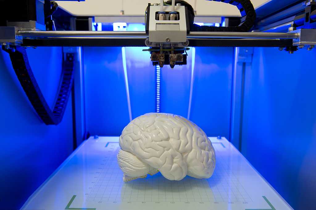 Our latest project involved constructing a larger model of the enzyme Photosystem II. We have made smaller models of this protein as well, but our attempt here is to build a larger structure for use in teaching applications and as a centerpiece model to illustrate what can be constructed with a simple entry-level 3D printer. Below are some pictures of earlier stages of the model. As can be seen, the painting and detailing for this model took quite some time. Check back for updates on this and other current models.
Our initial efforts in this area utilized a MakerBot Replicator 2, which was purchased through the support of the BioTechnology Institute at the University of Minnesota, and is housed in the Cargill Building on the St. Paul campus. Further worked utilized a MakerBot Fifth Generation which was supported as part of our broader impacts related to our funding through the National Science Foundation. For most of our models, we download pdb files from the Protein Data Bank, and using a range of software tools, we import a completed file into the MakerWare Software, which then prepares a file that is used to print a scaled 3 dimensional model of the protein or cofactor
In support of this technology and to further promote what I
feel is a potentially valuable educational tool, I have been building a number of these models and posting them to Thingiverse. Anyone can go to Thingiverse and download the files for printing on a MakerBot or comparable model printer. I have already constructed a model of the FeMo-cofactor, which is the complex metallocenter found in the enzyme nitrogenase, an enzyme I have studied for many years. I’ve also printed two models of the simple proteins Cytochrome C and Plastocyanin. I’ve also broken out the model paints and given them some color. You can find my work under MoleculeMaker on Thingiverse.
To construct our models, the coordinate files are downloaded from the Protein Data Bank as PDB files. We usually clean these up and remove any water molecules. These are then transferred to the program VMD, which is capable of producing an STL file, needed for import by the Makerware program. I usually select something specific from the protein to highlight. For example, I represent the heme molecule in cytochrome C as a CPK model, and then show the protein backbone. At this point, things get complicated, as VMD likes to layer the different representations on top of one another, which causes problems when trying to print. We use the online software Tinkercad to import the files, and then render a smaller file that removes all of the internal scaffolds, resulting in a much nicer print. Tinkercad was recently purchased by Autodesk. I have also tried using SketchUp, but this software has a much steeper learning curve. We are also interested in hearing from others that are using this 3 dimensional printing technology in similar applications, as there may be additional software tools that we are missing.
Several of my protein models have been constructed as they have relevance to the projects we work on in the laboratory. This model of the wax ester synthase enzyme is based on a theoretical structure we utilize in the laboratory for this wax ester synthase enzyme. Since there is currently no published crystal structure for this enzyme, we have to use structures from related enzymes as a “best guess” for what the structure of our enzyme might look like. Using this model, we have predicted where specific residues might reside in our model, and have selected these for site specific mutagenesis studies. These experiments have produced several interesting results which we recently published in the journal Applied and Environmental Microbiology (2013). We also published a paper in 2012 that characterized the differences between five homologs of this enzyme in the same journal. This enzyme is a key focus of study in our laboratory, as it produces an ester product from a fatty acid and a fatty alcohol. If the alcohol is small enough, then the product would be similar to biodiesel. When the enzyme produces the product of the fatty acid and an alcohol such as ethanol, then the product has been termed “microdiesel” by another research group, as it is derived from a microorganism. This enzyme may someday be utilized to produce biodiesel from simple feedstocks such as sugars, or from complex biomass such as cellulose. Most ideally, we would like to produce it in a functioning phototroph, such as a cyanobacterium. The use of the models is thus another tool to be used in our research efforts.
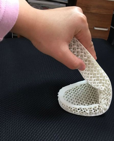
One drawback to our previous 3D prints is the excessive effort that is required to remove the scaffolding to support the molecule during the printing process.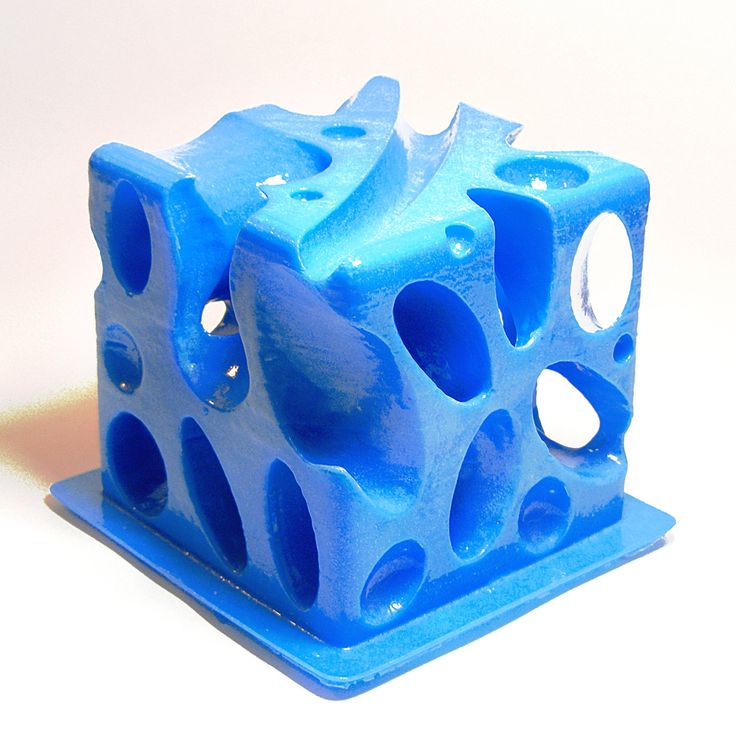 Based on some of the original support systems provided as defaults for software like Makerware, the process of removing the supports could take several hours and results in very sore hands and potential damage to the model. Thus, I have been working recently to improve certain models by incorporating our own structural supports. This results in less plastic utilized to print the model, and also drops down the time to remove the structure from several hours to a few minutes. It does require the use of a modeling knife to trim off the supports, but results in a much nicer looking final product.
To the left is the 3D model for the acyl carrier protein as is looks following printing, while the image to the right shows the model 30 minutes later following removal of the supports and some cleanup with a modeling knife to soften the edges. This model is very strong and retains shape better than some of my previous models. I am currently constructing a model of the enzyme quercetinase as well as a model of the substrate. This is a nice enzyme to do modeling with, as the substrate is large and the structure was solved with a substrate bound. My hope is to build a model that students can use to insert the substrate component into the active site, which will assist in their understanding of how enzymes orient substrates to improve catalysis. We also utilize the quercetinase enzyme as part of a teach laboratory experiment in our BBE3013 course at UMN.
The Complete Guide to Stereolithographic (SLA) 3D Printing
Stereolithographic (SLA) 3D printing is gaining immense popularity due to its ability to produce highly accurate, isotropic and waterproof prototypes and models with fine details and smooth surfaces from various modern materials.
This comprehensive guide explains how SLA printing technologies work, why thousands of professionals use them today, and how this 3D printing technology can be useful in your work.
White Paper
Download our white paper to find out how SLA printing works, why thousands of people use it today, and how this 3D printing technology can help your work.
Download white paper
The development of 3D printing technology continues to influence how companies approach prototyping and manufacturing. This technology is becoming more accessible, and equipment and materials are developing in accordance with the possibilities and requirements of the market. That's why today designers, engineers and others are integrating 3D printing into workflows at all stages of development.
3D printing is helping professionals across industries reduce recruitment costs, accelerate iteration, streamline manufacturing processes, and even discover entirely new business models.
Stereolithographic 3D printing technology has evolved significantly. In the past, resin 3D printers were monolithic and costly, requiring skilled technicians and costly service contracts to operate. Today's small desktop printers are highly flexible and produce industrial-quality products at a much lower cost.
Stereolithography is a type of additive manufacturing. It is also known as photopolymerization in the bath or 3D printing using polymer resin. Devices that use this technology have a common principle of operation: under the influence of a light source (laser or projector), a liquid polymer turns into a solid plastic. The main differences are in the location of the main components such as the light source, work platform and resin tank.
See how stereolithography 3D printing is done.
Stereolithographic 3D printers use light-sensitive curable materials called "polymers". When stereolithographic polymers are exposed to specific wavelengths of light, short molecular chains join together causing the monomers and oligomers to polymerize into either rigid or flexible patterns.
Graphical representation of the main mechanisms of stereolithographic 3D printing.
Models printed on SLA printers have the highest resolution and accuracy, the finest detail, and the smoothest surface of any 3D printing technology, but the main advantage of this method is its versatility.
Materials manufacturers have developed innovative formulas for stereolithographic polymers with a wide range of optical, mechanical and thermal properties similar to standard, engineering and industrial thermoplastic resins.
Comparison of 3D stereolithography with two other common plastic modeling technologies: Fused Deposition Modeling (FDM) and Selective Laser Sintering (SLS).
Sample
Experience the quality of 3D stereolithography for yourself. We will send a free sample of the printed model directly to your office.
Request a Free Print Sample
Learn how to go from design to 3D printing with a Form 3 3D printer. Watch this 5-minute video to learn the fundamentals of using a Form 3 printer, from software and materials to processes printing and post-processing.
Use any CAD software or 3D scan data to design the model and export it to a 3D print file format (STL or OBJ). All printers based on SLA technology work with software that allows you to set print parameters and separate the digital model into layers. After the settings are complete, the model preparation software sends instructions to the printer via a wireless or cable connection.
More advanced users can design directly for SLA technology or, for example, print models with voids to save materials.
After a quick check of the settings, the printing process starts. The printer may run unattended until printing is complete. In printers with a cartridge system, material is replenished automatically.
Formlabs' online Dashboard allows you to remotely manage printers, resins, and employee access.
After printing is complete, models should be rinsed with isopropyl alcohol to remove resin residue from their surface. After the washed models have dried, some materials require final polymerization, a process that ensures the best possible strength and stability of the parts. Finally, remove the support structures from the models and sand down the remaining traces of the supports for a clean finish.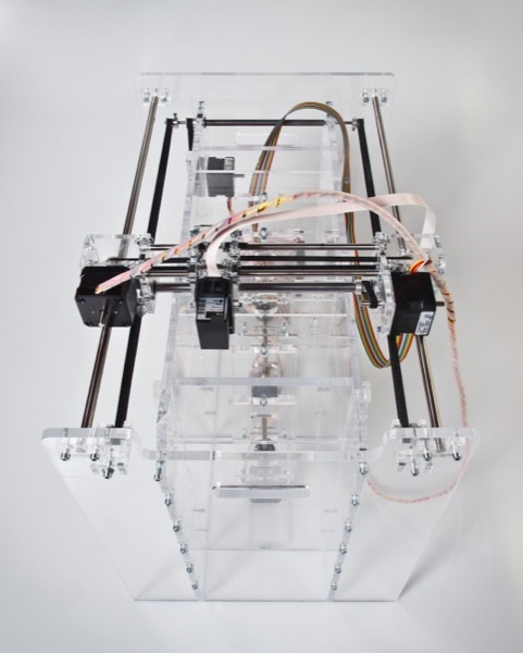 Models produced with SLA technology can be machined, primed, painted or assembled depending on the intended use.
Final polymerization is particularly important for functional polymer resins used in engineering, dentistry and jewellery.
Engineers, designers, fabricators and others choose 3D stereolithography because it provides excellent detail, smooth surfaces, superior model fidelity, isotropy, and water resistance. In addition, it allows you to work with various materials.
Because 3D printing builds models layer by layer, the strength of finished parts can vary depending on the orientation of the part relative to the printing process: the X, Y, and Z axes will have different properties.
Extrusion-based 3D printing processes such as deposition filament modeling (FDM) are anisotropic due to a special approach to creating different layers during the manufacturing process. This anisotropy limits the application of FDM technology or requires additional changes in the design of the model to compensate for it.
Check out our detailed guide comparing FDM vs. SLA 3D printers to see how they differ in terms of print quality, materials, application, workflow, speed, cost, and more.
Stereolithographic 3D printers, on the other hand, allow the production of highly isotropic models. Achieving detail isotropy relies on a number of factors that can be tightly controlled by integrating the chemical composition of materials with the printing process. During printing, the components of the polymers form covalent bonds, but when creating subsequent layers, the model remains in an "immature" state of partial reaction.
When immature, the resin retains polymerizable groups that can form bonds between layers, giving the model isotropic and waterproof properties after final curing. At the molecular level, there are no differences between the X, Y, and Z planes. This results in models with predictable mechanical characteristics critical for applications such as jigs and fixtures and finished parts, as well as functional prototyping.
SLA printed parts are highly isotropic compared to FDM parts.
Due to its isotropic nature, stereolithographic printed models, such as this jig for Pankl Racing Systems, can withstand directional loads during the manufacturing process.
SLA printed objects are continuous, whether they are solid or have internal channels. Watertightness is important when it is necessary to control and predict the impact of air or liquid flows. Engineers and designers are using the water resistance of stereolithography printers for air and fluid flow applications in the automotive industry, biomedical research, and to test the design of parts in consumer products such as kitchen appliances.
OXO relies on the water resistance of stereolithographic printed models to create durable working prototypes of air and liquid products such as coffee makers.
Stereolithographic 3D printing is used to produce precise, reproducible components in a variety of industries, including dentistry and manufacturing. In order to produce accurate models during the printing process, many factors must be strictly controlled.
The quality of stereolithographic 3D printing is between standard and precision machined. SLA has the highest tolerance compared to other commercial 3D printing technologies. Learn more about tolerances, accuracy and precision in 3D printing.
The heated resin tank combined with the closed working environment provide virtually the same conditions for every model. The higher accuracy also depends on the lower printing temperature compared to thermoplastic-based technologies in which the raw material is melted. Because stereolithography uses light instead of heat, it prints at close to room temperature and models are not subject to thermal expansion and contraction.
Dental example (comparison of a scanned component with the original CAD model) demonstrating the ability to maintain tight tolerances for the entire stereolithographic model.
LFS stereolithography 3D printing involves an optic in a Light Processing Unit (LPU) that moves along the x-axis. parabolic mirrors so that it is always perpendicular to the plane of the platform, so it always moves in a straight line, ensuring maximum precision and accuracy. This allows consistency to be achieved as the size of the equipment increases, for example, when working with a large-sized Formlabs Form 3L stereolithography printer. The LPU also uses a spatial filter, which forms a clear laser spot.
The characteristics of the individual materials also play an important role in ensuring the reliability and reproducibility of print results.
Formlabs Rigid Resin has a high green modulus, or modulus of elasticity, before final polymerization, allowing you to print very thin models with high precision and reliability.
Stereolithography printers are considered the best 3D printers due to the smooth surface of the produced models, the appearance of which is comparable to parts produced by traditional methods such as machining, injection molding and extrusion.
This surface quality is ideal when a perfect finish is needed and also helps reduce post-processing time because these models are easy to sand, polish and paint. For example, large companies like Gillette use stereolithography 3D printing to create finished products such as razor handles in their Razor Maker platform.
Large companies like Gillette use stereolithography 3D printing to create finished products such as razor handles in their Razor Maker platform.
The Z layer height is often used to determine the resolution of a 3D printer. On Formlabs stereolithographic 3D printers, it can be adjusted from 25 microns to 300 microns to trade off speed and print quality.
FDM and SLS printers typically print Z-axis layers between 100 and 300 microns wide. At the same time, a part printed with 100 micron layers on an FDM or SLS printer is very different from a part printed with 100 micron layers on an SLA printer. Models printed on a stereolithographic printer have a smoother surface immediately after printing, because their outer walls are straight, and each new printed layer interacts with the previous one, smoothing out the effect of the stairs. When printed on an FDM printer, layers are often visible in models, and the surface of models printed on an SLS printer has a grainy structure due to sintered powder.
In addition, the stereolithography printer can print fine details: the Form 3 laser spot size is 85 microns, while industrial SLS printers have a laser spot size of 350 microns, and FDM-based devices use nozzles with a diameter of 250– 800 microns.
Models printed on FDM printers often show layer lines and may have inaccuracies around complex features. Models printed on stereolithography printers have sharp edges, a smooth surface, and almost imperceptible layer lines.
The advantage of SLA polymers lies in a wide range of formulations offering a variety of characteristics: they can be soft or hard, contain additives such as glass and ceramics, or have special mechanical properties such as high bending temperature under load or impact resistance. Materials can be designed for a particular industry, such as dentures, or have properties close to those of final materials to create prototypes that can be tested and run under stress.
Ceramic Resin can be 3D printed with a stone-like texture and then fired to create a ceramic product.
In some cases, it is this combination of versatility and functionality that is leading businesses to use polymer-based 3D printing in-house. After solving existing problems through the use of a certain functional polymer, other applications are usually quickly discovered. In this case, the printer becomes a tool for discovering the various properties of various polymers.
For example, hundreds of engineers in the Design and Prototyping group at the Advanced Manufacturing Equipment Research Center (AMRC) at the University of Sheffield have access to 12 stereolithographic 3D printers and various construction materials that they use in numerous research projects for these partner companies like Boeing, Rolls-Royce, BAE Systems and Airbus. They printed High Temp Resin washers, brackets, and a mounting system for a sensor that must operate in high temperature conditions, and used Durable Resin to create complex spring components for a material handling robot as part of a composite manufacturing automation system.
AMRC engineers have access to 12 stereolithographic 3D printers and various construction materials, allowing them to create custom-designed parts for a variety of research projects, such as brackets for a stacking robot (above) and mounts for an environmental sensor. high temperature (below).
Material selection
Need help choosing a material for 3D printing? Our new interactive materials wizard will help you make the right material decision based on what you're going to use it for and the properties you care most about in our growing range of polymers.
Get material recommendations
Stereolithographic 3D printing makes it easier for businesses across industries to innovate. Such industries include engineering, manufacturing, dentistry, healthcare, education, entertainment, jewelry, and audiology.
Rapid prototyping with 3D printing enables engineers and developers to turn ideas into working proofs of concept, transform concepts into high-quality prototypes that look and work like end products, and take products through testing phases to launch into mass production.
Find out more
By creating the necessary prototypes and 3D printing special tools, molds and production aids, manufacturing companies can automate production and optimize workflows at a much lower cost and in much faster time than traditional manufacturing. Thus, production costs are reduced and defects are prevented, quality is improved, assembly is accelerated and labor productivity is increased.
Find out more
Digital Dentistry reduces the risks and uncertainties associated with human error, enabling consistent quality and precision at every step of the workflow, and improving patient care. 3D printers can produce a range of high quality custom products at low cost, providing exceptional fit and reproducible results.
Learn more
3D printers are multifunctional tools for creating immersive learning and research environments. They stimulate creativity and introduce students to professional-level technology, enabling the implementation of the STEAM method in the fields of science, technology, art and design.
Find out more
Affordable, professional-grade desktop 3D printers help clinicians produce medical devices that meet individual needs and improve patient outcomes. At the same time, the organization significantly reduces time and money costs: from laboratories to operating rooms.
Learn more
High resolution printed physical models are widely used in digital sculpting, 3D character modeling and prop making. 3D-printed models have been featured in animated films, video game characters, theatrical costumes, and even special effects for blockbuster films.
Learn more
Professional jewelers use the power of CAD and 3D printing to rapidly prototype, customize jewelry to customer specifications and produce large batches of blanks for casting. Digital tools allow you to create dense, highly detailed models without the tedious, error-prone production of stencils.
Learn more
Hearing professionals and labs use digital workflows and 3D printing to simplify the production of high-quality custom and hearing aids, as well as to mass-produce behind-the-ear hearing aids, hearing protectors, custom earmoulds, and headphones .
Find out more
Many companies are starting to use 3D printing technology through service bureaus and laboratories. Outsourcing can be a great solution when the need for 3D printing is infrequent or you need to do one-off jobs using materials that have unique properties or produce special models. Service bureaus can also provide advice on various materials and offer additional services such as design or improved finishes.
The main disadvantages of outsourcing are the high cost and duration of production. Often, outsourcing becomes a step on the way to in-house production as needs grow. One of the main advantages of 3D printing is its speed compared to traditional production methods. But it is noticeably reduced when the delivery of the model produced by the involved organization takes several days or even weeks. As demand and production capacity increase, the costs of outsourcing are rising rapidly.
With the increasing availability of industrial quality 3D printing today, more companies are opting to bring 3D printing into their factory right away, vertically integrating it into existing workshops or labs, or providing printers to engineers, designers and other professionals who benefit from digital transformation. projects into physical models or are engaged in the production of products in small batches.
Compact desktop stereolithography 3D printers are an excellent solution for rapid model production. Depending on the number of parts needed and the volume of prints, the investment in a compact 3D printer can pay for itself in just a few months. In addition, compact appliances allow you to purchase just the amount of equipment you need to run your business and scale your production by adding more units as demand grows. Using multiple 3D printers also allows you to print models from different materials at the same time. And when the need arises for the production of large parts or the use of non-standard materials, service bureaus can come to the rescue.
INTERACTIVE
Try our interactive ROI tool to see how much time and money you can save by printing with Formlabs 3D printers.
Calculate your savings
High production speed is an important reason to buy a desktop 3D printer. When working with a print bureau, there are delays related to the speed of production, communication and delivery. A desktop 3D printer like the Form 3 delivers models in hours, allowing designers and engineers to print multiple parts a day. This contributes to faster iterations and significant time savings in product development, as well as rapid testing of mechanisms and assemblies, avoiding costly tool changes.
Purchasing a desktop 3D printer saves a lot of money by eliminating bureau services and traditional processing methods, as their cost rises sharply with increasing demand and production volumes.
For example, the production engineer and others at Pankl Racing Systems used stereolithographic 3D printing technology to produce products on a tight schedule. This allowed them to independently manufacture custom-designed jigs and other small-sized components for the production line. While stereolithography was initially viewed with skepticism, this technology proved to be an ideal solution to replace the machining of a number of tools. In one of the cases, it made it possible to reduce the manufacturing time of conductors by
By 3D printing custom-designed jigs, Pankl Racing Systems has significantly reduced both order preparation time and production costs.
Compact units allow you to purchase just the amount of equipment you need to run your business and scale your production by adding new units as demand grows. Using multiple 3D printers also allows you to print models from different materials at the same time.
The University of Sheffield's Manufacturing Advanced Research Center (AMRC) has an additive manufacturing station with 12 Form 2 stereolithography (SLA) 3D printers that hundreds of engineers working on various projects have access to.
Formlabs offers two high-precision stereolithographic 3D printing systems, an ever-growing range of specialty materials, intuitive print preparation and process management software, and professional services, all in one solution.
To learn more about 3D stereolithography, experience it for yourself: request a free printed sample in your choice of material, delivered right to your door.
Request a print sample
Optimize your 3D printer design with glass transition simulation
Non-optimal cooling and curing rates in 3D printing can adversely affect manufactured parts and components.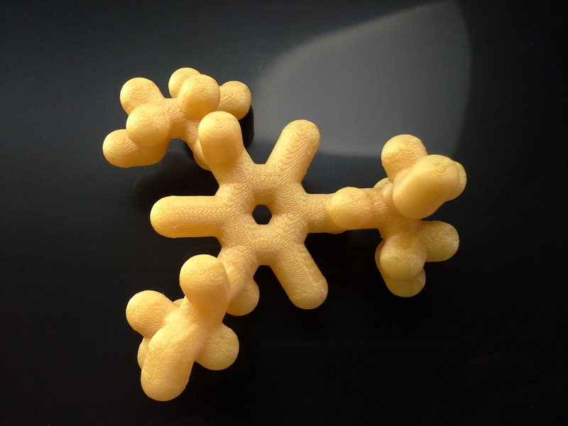 By optimizing the design of a 3D printer, high quality printed products can be ensured. One group of researchers used simulations to study the cooling process and resulting glass transition temperature of polymers in 3D printing. In this article, we will talk about how they simulated the process of extrusion of acrylonitrile butadiene styrene (ABS) in a 3D printer using the Fused Deposition Method (FDM®).
Fused deposition modeling is a common 3D printing method
3D printing, also known as additive manufacturing, is the process of creating three-dimensional objects in which material is deposited layer by layer from bottom to top. A common 3D printing method is Fusion Deposition (FDM®), which is used in rapid prototyping. When using the FDM™ method, 3D models are created using the extrusion process .
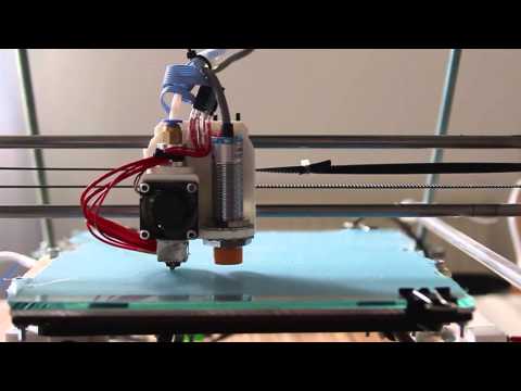
3D printer (left) and close-up of the 3D printer head (right). Images are from a presentation presented at COMSOL 2016 in Boston by Rahman, Schott, and Sadhu.
During the extrusion process, the thermoplastic is fed into the extruder, which is placed in the hot zone. The thermoplastic is melted and extruded from the extruder nozzle.
Researchers from the University of North and South, Department of Plastics Chemistry at the University of Massachusetts, Lowell, and IRays Teknology Ltd. in Bangladesh explored the application of conventional extrusion and modification technologies to commercial 3D printers. The modified design uses a continuous plastic tape on a large spool that is fed into the extruder as shown in the figure below.
The printer uses ABS thermoplastic (acrylonitrile butadiene styrene), one of two thermoplastics commonly used in the FDM® process. In the 3D printing process used in this study, the computer controls the movements of the extruder head, layer by layer creating a 3D object.
Extruder modified for use in a commercial 3D printer. The plastic tape is fed from a reel to an extruder where it is heated and pressured into a thin continuous stream of extruded plastic. This creates the layers of cured ABS that make up the finished three-dimensional product. Images taken from a talk presented at COMSOL 2016 in Boston by Rahman, Schott, and Sadhu.
The researchers planned to study the cooling steps and transients in the printer head using heat transfer simulations. They used the COMSOL Multiphysics® software package to determine how various factors affect the design of a 3D printer.
ABS Glass Transition Simulation in a 3D Printer
To accurately model the cooling and molding processes in 3D printing, a team of researchers developed a 2D axisymmetric model of a 3D printer head and studied its hydrodynamic and thermal properties, as well as the change in tensile modulus. It was assumed that ABS flows through a narrow nozzle in a continuous flow, and its volume does not change during curing. In addition, it was assumed that the ABS flow rate is constant and uniform.
Within the framework of such a model, the researchers studied the process of transition of ABS to a glassy state (glass transition). Glass transitions are reversible changes that occur in a plastic over a range of glass transition temperatures. As the temperature rises in this range, an amorphous material, such as ABS, changes from a hard and brittle state to a rubbery and viscous state.
This process takes place first when the ABS is heated to a melt state in the 3D printer's extruder and then when it cools and solidifies as it exits the extruder. This study was devoted specifically to the second-order transition to the glassy state.
Analysis of ABS extrusion in a 3D printer
Consider the extrusion process of ABS from a nozzle, which is shown in the figure at the bottom left. The results show that the ABS glass transition process is successful. In addition, the researchers planned to evaluate the effectiveness of this process.
Looking closely at the 3D printer head, we can see that the streamlines near the nozzle form a swirl. In a real 3D printer, this vortex flow can lead to uneven surface quality and product defects. By identifying a problem early in the design phase, engineers can improve the design of the nozzle from the start.
Left: Velocity plot obtained with one complete rotation of the 2D axisymmetric dataset. Right: surface velocity (mm/s) and total heat flow streamlines in the 3D printer head. Images taken from a talk presented at COMSOL 2016 in Boston by Rahman, Schott, and Sadhu.
Next, the scientists examined the heat flow shown in the graphs below. They were able to confirm that the conductive heat flux through the nozzle is very high. This was to be expected, since ABS releases a large amount of heat during the secondary phase transition.
Researchers have determined that the maximum heat flow is located in the center of the flow in the transition zone. Modeling the conductive heat flow at the outer boundary, the scientists found that most of the cooling occurs immediately at the exit of the nozzle. The simulation led to an interesting result: the heat flux is not constant, but varies along the length of the nozzle wall. This result is important for optimizing the cooling rate and choosing a cooling method in a 3D printer.
Left: conductive heat flow through the outer boundary. Right: scalar temperature field plot. The arrows indicate the direction of the total heat flux. Images taken from a talk presented at COMSOL 2016 in Boston by Rahman, Schott, and Sadhu.
In addition, the researchers were able to study how various factors affect the glass transition process of ABS. Thus, the following graph shows that smaller values of ΔT correspond to a sharper glass transition.
Percentage of plastic in the liquid phase along the centerline for various ΔT values. Images taken from a talk presented at COMSOL 2016 in Boston by Rahman, Schott, and Sadhu.
Optimize your 3D printer design with heat transfer simulation
While modeling the ABS glass transition in a 3D printer head, the researchers found a narrow region of the second order transition at the glass transition temperature.