3D print sls
Guide to Selective Laser Sintering (SLS) 3D Printing
Selective laser sintering (SLS) 3D printing is trusted by engineers and manufacturers across different industries for its ability to produce strong, functional parts.
In this extensive guide, we’ll cover the selective laser sintering process, the different systems and materials available on the market, the workflow for using SLS printers, the various applications, and when to consider using SLS 3D printing over other additive and traditional manufacturing methods.
White Paper
Looking for a 3D printer to create strong, functional parts? Download our white paper to learn how SLS printing works and why it's a popular 3D printing process for functional prototyping and end-use production.
Download the White Paper
Selective laser sintering is an additive manufacturing (AM) technology that uses a high-power laser to sinter small particles of polymer powder into a solid structure based on a 3D model.
SLS 3D printing has been a popular choice for engineers and manufacturers for decades. Low cost per part, high productivity, and established materials make the technology ideal for a range of applications from rapid prototyping to small-batch, bridge, or custom manufacturing.
Recent advances in machinery, materials, and software have made SLS printing accessible to a wider range of businesses, enabling more and more companies to use these tools that were previously limited to a few high-tech industries.
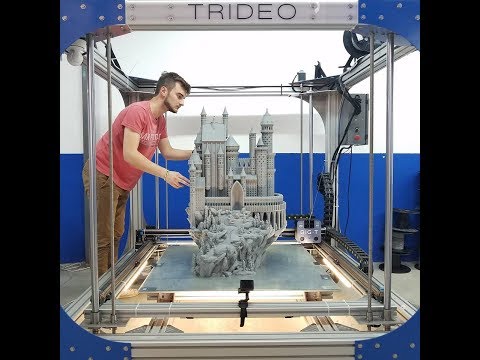
Introducing the Formlabs Fuse Series SLS 3D printers, bringing high-performance SLS 3D printing finally within reach.
Webinar
Watch our product demo for a walkthrough of the Fuse 1+ 30W and SLS 3D printing with Formlabs experts.
Watch the Webinar
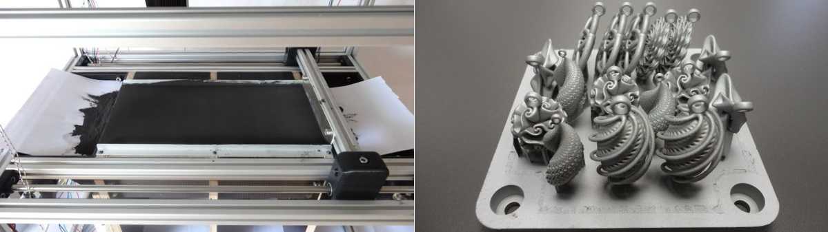
Schematic of the selective laser sintering process. SLS 3D printing uses a high-power laser to sinter small particles of polymer powder into a solid structure based on a 3D model.
-
Printing: The powder is dispersed in a thin layer on top of a platform inside of the build chamber. The printer preheats the powder to a temperature somewhat below the melting point of the raw material, which makes it easier for the laser to raise the temperature of specific regions of the powder bed as it traces the model to solidify a part. The laser scans a cross-section of the 3D model, heating the powder to just below or right at the melting point of the material. This fuses the particles together mechanically to create one solid part. The unfused powder supports the part during printing and eliminates the need for dedicated support structures. The platform then lowers by one layer into the build chamber, typically between 50 to 200 microns, and the process repeats for each layer until parts are complete.
-
Cooling: After printing, the build chamber needs to slightly cool down inside the print enclosure and then outside the printer to ensure optimal mechanical properties and avoid warping in parts.
-
Post-processing: The finished parts need to be removed from the build chamber, separated, and cleaned of excess powder. The powder can be recycled and the printed parts can be further post-processed by media blasting or media tumbling.
For the detailed workflow, see the “The SLS 3D Printing Workflow” section below.
SLS parts have a slightly grainy surface finish, but almost no visible layer lines. Media blasting or media tumbling SLS parts is recommended for a smoother surface finish. This example part was printed on a Formlabs Fuse 1+ 30W benchtop industrial SLS 3D printer.
As the unfused powder supports the part during printing, there’s no need for dedicated support structures. This makes SLS ideal for complex geometries, including interior features, undercuts, thin walls, and negative features.
Parts produced with SLS 3D printing have excellent mechanical characteristics, with strength resembling injection-molded parts.
Sample part
See and feel Formlabs quality firsthand. We’ll ship a free SLS sample part printed on the Fuse 1+ 30W to your office.
Request a Free Sample Part
FDM vs SLA vs SLS: Compare selective laser sintering (SLS) 3D printing to two other common 3D printing processes for producing plastic parts: fused deposition modeling (FDM) and stereolithography (SLA).
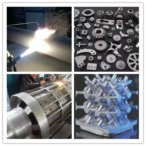
Selective laser sintering was one of the first additive manufacturing techniques, developed in the mid-1980s by Dr. Carl Deckard and Dr. Joe Beaman at the University of Texas at Austin. Their method has since been adapted to work with a range of materials, including plastics, metals, glass, ceramics, and various composite material powders. Today, these technologies are collectively categorized as powder bed fusion—additive manufacturing processes in which thermal energy selectively fuses regions of a powder bed.
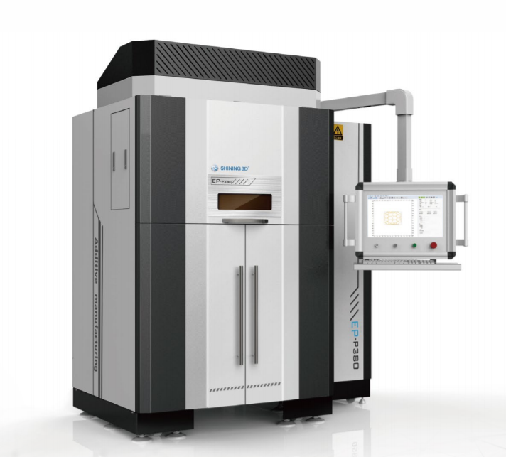
The two most common powder bed fusion 3D printing systems today are plastic-based, commonly referred to as SLS, and metal-based, known as direct metal laser sintering (DMLS) or selective laser melting (SLM). Until recently, both plastic and metal powder bed fusion systems have been prohibitively expensive and complex, limiting their use to small quantities of high-value or custom parts, such as aerospace components or medical devices.
Innovation in the field has surged recently, and plastic-based SLS is now poised to follow other 3D printing technologies like stereolithography (SLA) and fused deposition modeling (FDM) to gain widespread adoption with accessible, compact systems.
All selective laser sintering 3D printers are built around the process described in the previous section. The main differentiators are the type of laser, the size of the build volume, and the complexity of the system. Different machines use different solutions for temperature control, powder dispensing, and layer deposition.
Selective laser sintering requires a high level of precision and tight control throughout the printing process. The temperature of the powder along with the (incomplete) parts must be controlled within 2 °C during the three stages of preheating, sintering, and storing before removal to minimize warping, stresses, and heat-induced distortion.
Selective laser sintering has been one of the most popular 3D printing technologies for professionals for decades, but its complexity, requirements, and high price have limited its use to service bureaus and large enterprises.
These machines require special HVAC and industrial power, and even the smallest industrial machines take up at least 10 m² of installation space. Setting them up takes multiple days with on-site installation and training. The complex workflow and the steep learning curve also mean that these systems require a skilled technician in-house to operate and maintain.
With a starting price of around $200,000 that goes well beyond that for complete solutions, traditional industrial SLS has been inaccessible for many businesses.
Just like with other 3D printing technologies like FDM or SLA, lower-cost, compact SLS systems have recently started to emerge on the market, but initially, these solutions came with considerable trade-offs, including lower part quality and complex, manual workflows resulting from the lack of post-processing solutions, which limited their use in industrial and production settings.
The Formlabs Fuse 1 bridged that gap and created its own category as the first benchtop industrial SLS 3D printer that offered high quality, compact footprint, and a complete, simplified workflow at a fraction of the cost of traditional industrial SLS systems. Now, the next generation Fuse 1+ 30W extends that category with a more powerful laser, improved powder handling features, and new material capabilities for industrial quality parts and high throughput.
The Fuse 1+ 30W requires no specialized infrastructure, and can easily fit into your workspace.
Fuse Series SLS 3D printers use a single laser and a smaller build chamber that requires less heating. The lower energy consumption means that they can run on standard AC power without requiring specialized infrastructure. An optional nitrogen feature for the Fuse 1+ 30W printer creates an inert gas environment, preserving the quality of the unsintered powder for a lower refresh rate (more recycled powder than new powder in consecutive builds), minimizing waste, and enabling a better surface finish on sintered parts.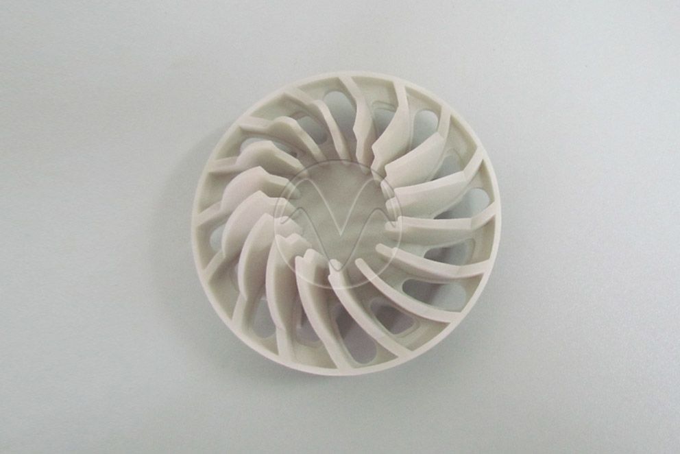
Fuse Series printers also feature a patent-pending solution called Surface Armor—a semi-sintered shell that keeps the area around the parts evenly heated as they print, ensuring great surface finish, consistent mechanical properties, high reliability, and better refresh rates.
To offer a compact, contained ecosystem and end-to-end powder handling, Fuse Series printers also come with the Fuse Sift, which combines part extraction, powder recovery, storage, and mixing in a single free-standing device.
Overall, benchtop industrial SLS 3D printing with Fuse Series printers offers a slightly smaller build volume compared to the entry-level traditional SLS systems, in return for a substantially smaller footprint, simplified workflow, and lower cost.
| Fuse Series: Benchtop Industrial SLS 3D Printers | Traditional Industrial SLS 3D Printers | |
|---|---|---|
| Price | Starting at $18,500 for the Fuse 1, $28,000 for the Fuse 1+ 30W | $200,000-$500,000+ |
| Print Volume | Up to 165 x 165 x 300 mm | Up to 550 x 550 x 750 mm |
| Pros | Affordable High-quality parts High throughput Multiple material options Simplified workflow Small footprint Low maintenance | Large build volume High-quality parts High throughput Multiple material options |
| Cons | Smaller build volume | Expensive machinery Large footprint Facility requirements High maintenance Requires a dedicated operator |
The comparison is based on the Formlabs Fuse Series benchtop industrial SLS system and traditional industrial SLS systems by EOS and 3D Systems.
A drill prototype printed on the Fuse 1+ 30W (left) and on an EOS printer (right), with comparable quality but a vastly different machine price point.
White Paper
In this white paper, we evaluate the value proposition of bringing SLS 3D printers in-house, in comparison with outsourcing SLS parts from a service bureau.
Download the White Paper
The most common material for selective laser sintering is nylon, a highly capable engineering thermoplastic for both functional prototyping and end-use production. Nylon is ideal for complex assemblies and durable parts with high environmental stability.
SLS 3D printed nylon parts are strong, stiff, sturdy, and durable. The final parts are impact-resistant and can endure repeated wear and tear. Nylon is resistant to UV, light, heat, moisture, solvents, temperature, and water. 3D printed nylon parts can also be biocompatible and not sensitizing, which means that they are ready to wear and safe to use in many contexts.
Nylon is ideal for a range of functional applications, from engineering consumer products to healthcare.
Nylon is a synthetic thermoplastic polymer that belongs to the family of polyamides. It is available in multiple variants, each tailored to different applications. Nylon 12 Powder and Nylon 11 Powder are single-component powders, while Nylon 12 GF Powder is a glass-filled composite, and Nylon 11 CF Powder is a carbon fiber reinforced composite. These composite materials are developed to optimize parts for higher strength, stiffness, or flexibility. With these two-component powders, only the component with the lower glass transition point is sintered, binding both components.
- High performance prototyping
- Small batch manufacturing
- Permanent jigs, fixtures, and tooling
- General SLS parts
- Impact-resistant prototypes, jigs, and fixtures
- Thin-walled ducts and enclosures
- Snaps, clips, and hinges
- Orthotics and prosthetics*
- Robust jigs and fixtures and replacement parts
- Parts undergoing sustained loading
- Threads and sockets
- Parts subjected to high temperature
- Replacement and spare alternatives to metal parts
- Tooling, jigs, fixtures
- High-impact equipment
- Functional composite prototypes
* Material properties may vary based on part design and manufacturing practices.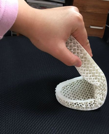 It is the manufacturer’s responsibility to validate the suitability of the printed parts for the intended use.
| Materials | Nylon 12 Powder | Nylon 11 Powder | Nylon 12 GF Powder | Nylon 11 CF Powder |
|---|---|---|---|---|
| Ultimate Tensile Strength X (MPa) | 50 | 49 | 38 | 69 |
| Ultimate Tensile Strength Y (MPa) | N/A | N/A | N/A | 52 |
| Ultimate Tensile Strength Z (MPa) | N/A | N/A | N/A | 38 |
| Tensile Modulus X (MPa) | 1850 | 1600 | 2800 | 5300 |
| Elongation at Break, X/Y (%) | 11 | 40 | 4 | 9 / 15 |
| Elongation at Break, Z (%) | 6 | N/A | 3 | 5 |
| Notched Izod (J/m) | 32 | 71 | 36 | 74 |
SLS 3D printing accelerates innovation and supports businesses across a wide range of industries, including engineering, manufacturing, and healthcare.
Take control of your entire product development process, from iterating on your first concept design to manufacturing ready-to-use products:
- Rapid prototyping
- Mockups of products for in-field customer feedback
- Functional prototyping
- Rigorous functional testing of products (e.g. ductwork, brackets)
Own your supply chain and respond quickly to changing demands:
- End-use part production
- Small batch, stop-gap, and bridge manufacturing
- Mass customized consumer products
- Replacement parts, aftermarket parts, spare parts
- Long-lasting, durable manufacturing aids, jigs and fixtures (e.g clips and clamps) and tooling
- Custom automotive or motorcycle parts, marine equipment, military ‘resupply on-demand’
Manufacture ready-to-use, patient-specific medical devices in-house:
- Medical device prototyping
- Prosthetics and orthotics (i.e. limb replacements + braces)
- Surgical models + tools
- End-use parts (Nylon 12 Powder is biocompatible + compatible with sterilization*)
* Material properties may vary based on part design and manufacturing practices. It is the manufacturer’s responsibility to validate the suitability of the printed parts for the intended use.
White Paper
This white paper showcases the cost-dynamics for real-life use cases, and presents guidelines for using SLS 3D printing, injection molding, or both.
Download the White Paper
Webinar
In this webinar, learn how affordable industrial-quality SLS 3D printers are making additive manufacturing a viable choice for end-use production and mass customization.
Watch the Webinar Now
Watch this video to see the step by step process of using the Fuse 1 selective laser sintering (SLS) 3D printer and the Fuse Sift powder recovery station.
Use any CAD software or 3D scan data to design your model, and export it in a 3D printable file format (STL or OBJ). Each SLS printer includes software to specify printing settings, orient and arrange models, estimate print times, and slice the digital model into layers for printing. Once setup is complete, the print preparation software sends the instructions to the printer via a wireless or cable connection.
Fuse Series printers use PreForm print preparation software (free to download) that allows you to seamlessly duplicate and organize multiple parts within a 3D grid to use as much of the build space as possible for a single print. PreForm automatically suggests optimal orientation and part packing, with the ability to manually refine as needed.
The workflow for preparing the printer varies by system. Most traditional SLS systems require extensive training, tools, and physical effort to prepare and maintain.
Fuse Series printers reimagine the SLS workflow for simplicity and efficiency, with modular components to enable nonstop printing and end-to-end powder handling.
On Fuse Series printers, you can load powder easily using the powder cartridge.
Fuse Series printers use a removable build chamber so you can run another print while a previous one is still cooling.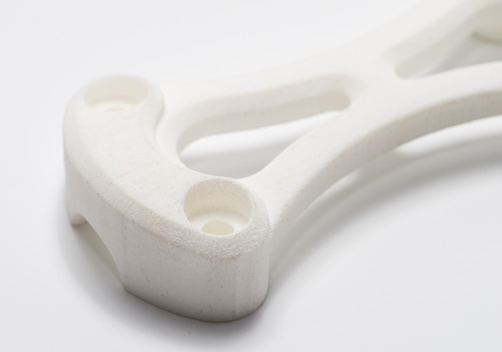
Once all preprint checks have been completed, the machine is ready to print. SLS 3D prints can take anywhere from a few hours to multiple days depending on the size and complexity of parts, as well as the part density.
Once the print is finished, the build chamber needs to slightly cool down in the print enclosure before moving to the next step. After that, the build chamber can be removed and a new one inserted to run another print. The build chamber has to cool down before post-processing to ensure the optimal mechanical properties and avoid warping in parts. This may take up to half of the print time.
On Fuse Series printers, the touchscreen displays a live stream of the print bed during printing so you can watch each new layer take shape. This camera view is also available from your computer in PreForm so you can monitor your print without leaving your desk.
Post-processing SLS parts requires minimal time and labor compared to other 3D printing processes. It is easily scalable and yields consistent results for batches of parts thanks to the lack of support structures.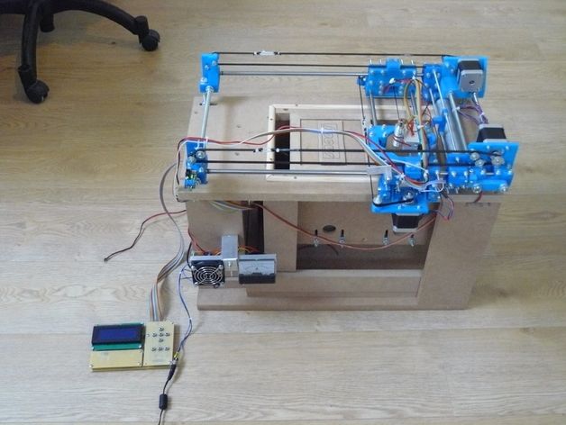
After a print job is complete, remove the finished parts from the build chamber, separate them, and clean them of excess powder. This process is typically completed manually at a cleaning station using compressed air or a media blaster.
Any excess powder remaining after part recovery is filtered to remove larger particles and can be recycled. Unfused powder degrades slightly with exposure to high temperatures, so it should be refreshed with new material for subsequent print jobs. This ability to re-use the material for subsequent jobs makes SLS one of the least wasteful manufacturing methods.
A common theme in the SLS industry is to offer separate devices for reclaiming, storing, and mixing powder. In the Fuse Series workflow, a single device, Fuse Sift, handles the extraction of parts and unsintered powder, as well as storing, dosing, and mixing of streams.
For Fuse Series printers, Fuse Sift completes the SLS printing workflow. It offers a safe and efficient system for extracting prints and recycling powder.
Fuse Sift can dispense and mix used and new powder automatically so you can reduce waste and control your powder supply.
SLS 3D printed parts are ready to use after sifting. However, there are several other post-processing steps that you might consider for selective laser sintered parts.
By default, SLS 3D prints have a grainy finish. Formlabs recommends media blasting or media tumbling SLS parts for a smoother surface finish. Parts may be spray painted, lacquered, electroplated, and coated to achieve different colors, finishes, and properties, for example, watertightness (coating) and conductivity (electroplating). Formlabs SLS parts are dark in color, so they are not ideal for dyeing.
SLS part with hydrographics from Partial Hand Solutions.
SLS parts can be electroplated for a metal-like finish.
Engineers and manufacturers choose selective laser sintering for its design freedom, high productivity and throughput, low cost per part, and proven, end-use materials.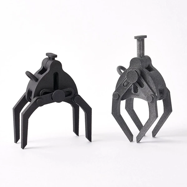
Most additive manufacturing processes, such as stereolithography (SLA) and fused deposition modeling (FDM), require specialized support structures to fabricate designs with overhanging features.
Selective laser sintering does not require support structures because unsintered powder surrounds the parts during printing. SLS printing can produce previously impossible complex geometries, such as interlocking or moving parts, parts with interior components or channels, and other highly complex designs.
Hand splint designed with a complex pattern to reduce weight.
Engineers generally design parts with the capabilities of the final manufacturing process in mind, also known as design for manufacturing (DFM). When additive manufacturing is used for prototyping alone, it is limited to parts and designs that conventional manufacturing tools can ultimately reproduce during production.
As selective laser sintering becomes a viable rapid manufacturing method for an increasing number of end-use applications, it has the potential to unleash new possibilities for design and engineering.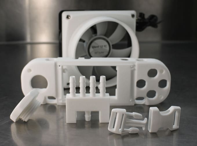 SLS 3D printers can produce complex geometries that are impossible or prohibitively costly to manufacture with traditional processes. SLS also empowers designers to consolidate complex assemblies that would normally require multiple parts into a single part. This helps alleviate weak joints and cuts down on assembly time.
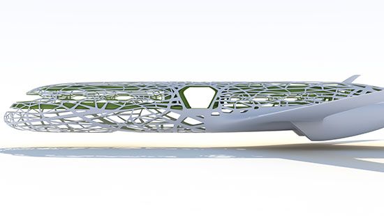
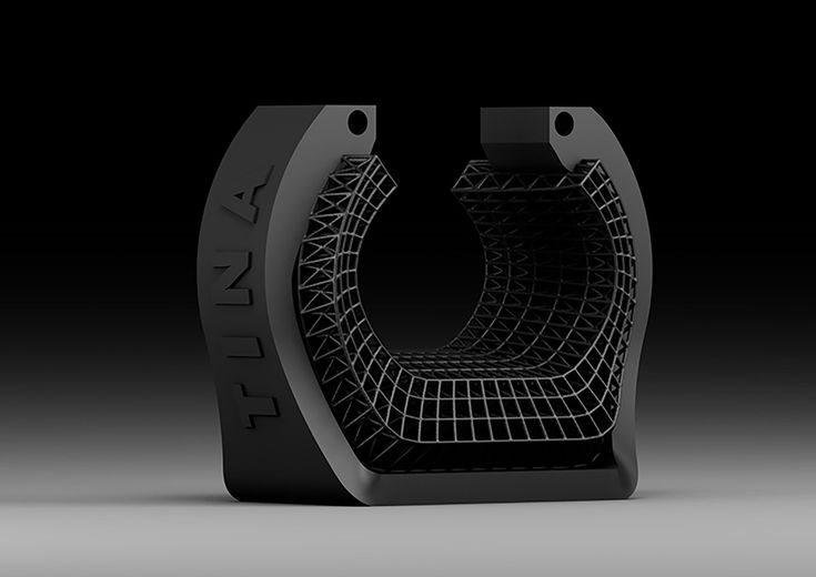
Selective laser sintering can take generative design to its full potential by enabling lightweight designs that employ complex lattice structures impossible to manufacture with traditional methods.
SLS printing is the fastest additive manufacturing technology for functional, durable prototypes and end-use parts. The lasers that fuse the powder have a much faster scanning speed and are more accurate than the layer deposition methods used in other processes like industrial FDM.
Multiple parts can be tightly arranged during printing to maximize the available build space in each machine. Operators use software to optimize each build for the highest productivity leaving only minimal clearance between parts.
SLS allows operators to pack the build chamber with as many parts it can fit and print them without supports to save time in post-processing.
The key to SLS 3D printing’s functionality and versatility is the materials. Nylon and its composites are proven, high-quality thermoplastics. Laser-sintered nylon parts have close to 100 percent density with mechanical properties comparable to parts created with conventional manufacturing methods like injection molding.
Drill assembly printed in Nylon 12 Powder. Nylon parts can be easily post-processed to achieve smooth, professional surface finishes.
SLS nylon is a great substitute for common injection molded plastics. It offers superior snap fits and mechanical joints compared to any other additive manufacturing technology. It is ideal for functional applications requiring plastic parts that will last where parts produced with other AM methods would degrade and become brittle over time.
Calculating cost per part usually requires accounting for equipment ownership, material, and labor costs:
-
Equipment ownership: The more parts a machine can produce over its lifetime, the lower the costs attributable to each individual part.
 Consequently, higher productivity leads to lower equipment ownership costs on a per-part basis. Given the fast scanning speed of the laser, the nesting of parts to maximize build capacity, and simple post-processing, SLS 3D printing offers the highest productivity and throughput of all plastic additive manufacturing techniques.
 -
Material: While most 3D printing technologies use proprietary materials, nylon is a common thermoplastic produced in large quantities for industrial purposes, making it one of the least expensive raw materials for additive manufacturing. As SLS 3D printing doesn’t require support structures and allows for printing with recycled powder, the process produces minimal waste.
-
Labor: The Achilles heel of many 3D printing solutions is labor. Most processes have complex workflows that are hard to automate, which can substantially influence the cost per part. The simple post-processing workflow of SLS printing means less labor is required and the process is easy to scale.
An SLS 3D printer represents a substantial initial investment, but it can often recoup the initial investment even faster than smaller machines. Benchtop SLS significantly reduces this barrier to entry and also the per par cost for most applications.
Outsourcing production to service bureaus is recommended when your business requires 3D printing only occasionally, but it also comes with higher costs and long lead times. One of the greatest benefits of 3D printing is its speed compared to traditional manufacturing methods, which quickly diminishes when an outsourced part takes a week or even multiple weeks to arrive.
| Cost | Lead Time | |
| Service Bureau | $118.33 | 7-10 days |
| Fuse 1+ 30W | $9.02 | 13 hours |
Interactive
Try our interactive ROI tool to see how much time and cost you can save when 3D printing on Formlabs 3D printers.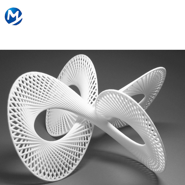
Calculate Your Savings
Selective laser sintering enables engineers to prototype parts early in the design cycle, then use the same machine and material to produce end-use parts. SLS 3D printing does not require the same expensive and time-consuming tooling as traditional manufacturing, so prototypes of parts and assemblies can be tested and easily modified over the course of a few days. This drastically reduces product development time.
SLS 3D is ideal for creating durable, functional prototypes that are ready to undergo rigorous functional testing or to ship to customers as replacement parts or products that are ready to use.
Given its low cost per part and durable materials, SLS 3D printing is an economical way to produce complex, custom parts, or a series of small components for end products. In many cases, laser sintering is a cost-effective alternative to injection molding for limited-run or bridge manufacturing.
Until now, industrial SLS 3D printers have been prohibitively costly for most businesses, with a single machine running over $200,000.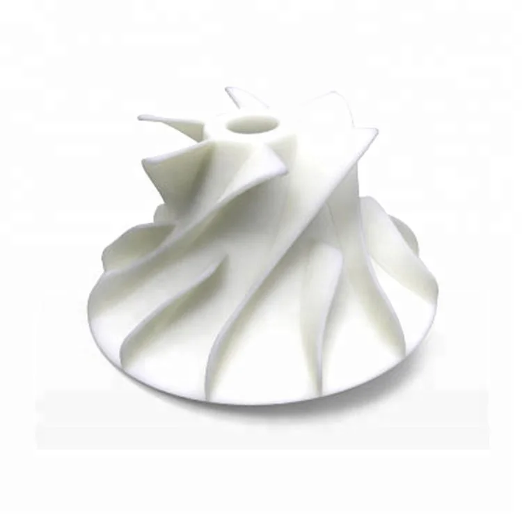
With the Fuse 1+ 30W, Formlabs is bringing the industrial power of selective laser sintering to the benchtop, offering high-performance materials at the lowest cost per part, with a compact footprint and simple workflow.
A new wave of independent manufacturing and prototyping starts now with the Fuse 1+ 30W.
See the Fuse 1+ 30W Benchtop Industrial SLS 3D Printer
What is SLS 3D printing?
Learn about the basic principles of selective laser sintering, also known as SLS 3D printing. Discover how SLS 3D printing works, the advantages of SLS techniques for rapid prototyping and low-production runs, and the various materials and options available that will suit your part or project.
Selective Laser Sintering (SLS) is an additive manufacturing process that belongs to the Powder Bed Fusion family. In SLS 3D printing, a laser selectively sinters the particles of a polymer powder, fusing them together and building a part, layer by layer. The materials used in SLS are thermoplastic polymers that come in a granular form. A SLS 3D printing service is used for both prototyping of functional polymer components and for small production runs. Its versatility makes SLS a great alternative to injection molding for low-production runs.
How does SLS 3D printing work?
SLS 3D printing uses a laser to sinter small particles of polymer powder. The entire cross-section of the component is scanned, so the part is built solid. The process works as follows:
-
The powder bin and the build area are first heated to just below the melting temperature of the polymer.
-
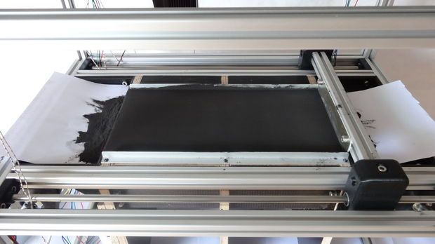
A re-coating blade spreads a thin layer of powder over the build platform.
-
A CO2 laser then scans the contour of the next layer and selectively sinters—fuses together—the particles of the polymer powder.
-
When a layer is complete, the build platform moves downwards and the blade re-coats the surface.
 The process then repeats until the whole part is complete.
 -
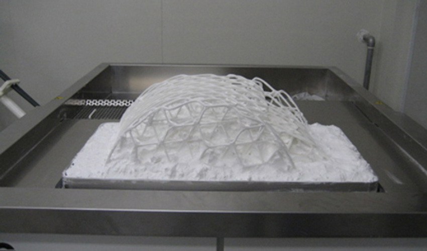
After printing, the parts are fully encapsulated in the unsintered powder. The powder bin must cool before the parts can be unpacked, which can take a considerable amount of time—sometimes up to 12 hours.
-
The parts are then cleaned with compressed air or another blasting media, then they are ready to use or further post-process.
Watch the SLS process in action in this 30-second video.
Can you use SLS 3D printing for rapid prototyping?
SLS is a great solution for the rapid prototyping of functional polymers because it offers a very high degree of design freedom and high accuracy. And unlike FDM or SLA 3D printing techniques, it produces parts with good and consistent mechanical properties.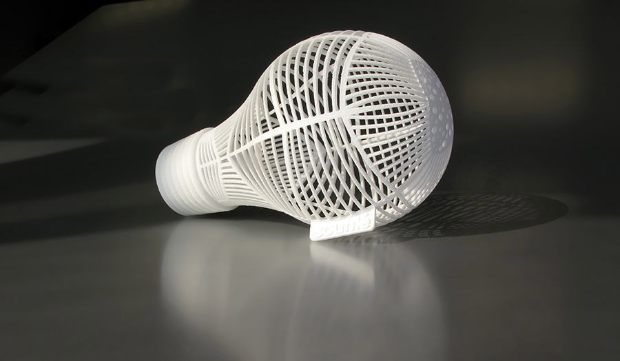 This means it can be used to produce parts that are very close to end-use quality, so you can use it throughout the production process, from concept to trial models.
Can you use SLS 3D printing for low-production runs?
Its versatility makes SLS 3D printing an ideal alternative to injection molding for low-production runs. SLS can be used to manufacture parts with complex shapes and geometries, and with a wide variety of finishes and lead times.
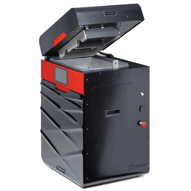
How does an SLS 3D printer work?
Schematic of a SLS printerFor use of an SLS 3D printer, almost all process parameters are preset by the machine manufacturer. The default layer height used is 100–120 microns.
A key advantage of SLS 3D printing is that it needs no support structures. The unsintered powder provides the part with all the necessary support. For this reason, SLS can be used to create free-form geometries that are impossible to manufacture with any other method.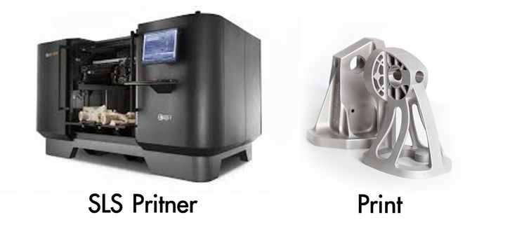
Taking advantage of the whole build volume is very important when printing with SLS, especially for small batch productions . A bin of a given height will take about the same time to print, independent of the number of parts it contains. This is because laser scanning occurs very rapidly, so it’s actually the re-coating step which determines the total processing time. The machine will have to cycle through the same number of layers regardless of the number of parts. Bin packing may affect lead times of small orders, as operators may wait until a bin is filled before starting a print task.
Layer Adhesion
The bond strength between layers in SLS 3D printing is excellent. This means that SLS printed parts have almost isotropic mechanical properties.
The mechanical properties of SLS specimens printed using standard polyamide powder ( PA 12 or Nylon 12)—the most commonly used material in SLS—are shown in the next table and compared to the properties of bulk nylon.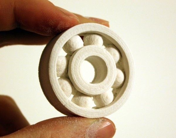
| X-Y direction | Z direction | Bulk PA12 | |
|---|---|---|---|
| Tensile Strength | 48 MPa | 42 MPa | 35–55 MPa |
| Tensile Modulus | 1650 MPa | 1650 MPa | 1270–2600 MPa |
| Elongation at break | 18% | 4% | 120–300% |
SLS parts have excellent tensile strength and modulus, comparable to the bulk material, but are more brittle—their elongation at break is much lower. This is due to the internal porosity of the final part.
Shrinkage & Warping
SLS parts are susceptible to shrinkage and warping. As the newly sintered layer cools, its dimensions decrease and internal stresses buildup, pulling the underlying layer upwards.
Three to 3.5% shrinkage is typical in SLS, but machine operators take this into account during the build preparation phase and adjust the size of the design accordingly.
Large flat surfaces are the most likely to warp. The issue can be mitigated somewhat by orientating the part vertically in the build platform, but the best practice is to reduce its volume by minimizing the thickness of the flat areas and by introducing cutouts to the design. This strategy will also reduce the overall cost of the part, as less material is used.
Oversintering
Oversintering occurs when radiant heat fuses unsintered powder around a feature. This can result in loss of detail in small features, such as slots and holes. As a rule of thumb, slots wider than 0.8mm and holes with diameter larger than 2mm can be printed in SLS without fear of oversintering. Read our article on how to design parts for SLS 3D printing for more DFM tips.
Powder Removal
Since SLS requires no support material, parts with hollow sections can be printed easily and accurately.
Hollow sections reduce the weight and cost of a part, as less material is used. Escape holes are needed to remove the unsintered powder from the inner sections of the component. We recommend adding at least two escape holes to your design, with a minimum diameter of 5mm.
If a high degree of stiffness is required, parts must be printed fully solid. An alternative is to make a hollow design omitting the escape holes. In this way, tightly packed powder will be entrapped in the part, increasing its mass and providing some additional support against mechanical loads, without an effect on the build time. An internal honeycomb lattice structure can be added to the hollowed interior (similar to the infill patterns used in FDM ) to further increase the stiffness of the component. Hollowing a part this way may also reduce warping.
What are the characteristics of SLS 3D printing?
The main characteristics of SLA are summarized in the table below:
| Selective Laser Sintering (SLS) | |
|---|---|
| Materials | Thermoplastics (usually nylon) |
| Dimensional accuracy | ± 0. 3% (lower limit of ± 0.3 mm) 3% (lower limit of ± 0.3 mm) |
| Typical build size | 300 x 300 x 300mm (up to 750 x 550 x 550mm) |
| Common layer thickness | 100–120 µm |
| Support | Not required |
What materials are used for SLS printing?
The most widely used SLS material is Polyamide 12 (PA 12), also known as Nylon 12. The price per kilogram of PA 12 powder is approximately $50–$60. Other engineering plastics such as PA 11 and PEEKare also available, but these are not as widely used.
Polyamide powder can be filled with various additives to improve the mechanical and thermal behavior of the produced SLS part. Examples of additives include carbon fibers, glass fibers or aluminium. Materials filled with additives are usually more brittle and can have highly anisotropic behavior.
| Material | Characteristics |
|---|---|
| Polyamide 12 (PA 12) | + Good mechanical properties + Good chemical resistance - Matte, rough surface |
| Polyamide 11 (PA 11) | + Fully isotropic behavior + High elasticity |
| Aluminium-filled nylon (Alumide) | + Metallic appearance + High stiffness |
| Glass-filled nylon (PA-GF) | + High stiffness + High wear & temperature resistance - Anisotropic behavior |
| Carbon-fiber filled nylon (PA-FR) | + Excellent stiffness + High weight-strength ratio - Highly anisotropic |
What are the options for SLS post-processing?
SLS 3D printing produces parts with a powdery, grainy surface finish that can be easily stained. The appearance of SLS printed parts can be improved to a very high standard using various post-processing methods, such as media polishing, dyeing, spray painting and lacquering. Their functionality can also be enhanced by applying a watertight coating or a metal plating. For more details, check out this extensive article on post-processing for SLS parts.
What are the advantages of SLS 3D printing
-
SLS parts have good, isotropic mechanical properties, making them ideal for functional parts and prototypes.
-
SLS requires no support, so designs with complex geometries can be easily produced.
-
The manufacturing capabilities of SLS is excellent for small to medium batch production.
-
All remaining unsintered powder is collected and can be reused.
What are the disadvantages of SLA 3D printing?
-
Only industrial SLS systems are currently widely available, so lead times are longer than other 3D printing technologies , such as FDM and SLA.
-
SLS parts have a grainy surface finish and internal porosity that may require post processing, if a smooth surface or watertightness are required.
-
Large flat surfaces and small holes cannot be printed accurately with SLS, as they are susceptible to warping and oversintering.
SLS best practices
Is SLS 3D printing right for your part or project? These are the rules of thumb:
-
SLS can produce functional parts from a large range of engineering plastics—most commonly Nylon (PA12).
-
The typical build volume of an SLS system is 300 x 300 x 300mm.
-
SLS parts exhibit good mechanical properties and isotropic behavior. For components with special requirements, additive-filled PA powders are available.
Ready to transform your CAD file into a custom part? Upload your designs for a free, instant quote.
 Get an instant quote
Preparing models for 3D printing: Materialize Magics features
3D basics
Software
Author: Kirill Romanov
Author: Kirill Romanov
Materialize Magics: An all-in-one 3D printing program | What is included in the software | Magics RP Base Module Capabilities | Additional modules | Benefits of Magics
How models are prepared for 3D printing
Additive manufacturing starts with the modeling of objects, which is carried out in various programs such as CATIA, SketchUp, SolidWorks, Inventor, Siemens NX and others. In order to print a product, it is necessary to prepare its digital model, and this process can take up to 32% of the time of the entire additive manufacturing cycle, depending on the technology and complexity of the object.
To manufacture a part on a 3D printer, first of all, you need to get an STL file. To do this, we convert a rigid body to a polygonal model, and then perform the operations of correction, enhancement, editing, platform preparation, nesting, generation of supporting structures, measurements and analysis.
The next stage is slicing (separation into layers), which consists in creating a control program for a 3D printer. The model is divided into layers with a certain step, and on each layer we get a closed contour, along which the extruder or printer's laser beam will pass. Each layer is usually a 2D DXF image.
Applying Materialize Magics Software to the Additive Manufacturing Cycle
Next, the object is printed and undergoes the necessary post-processing. The stages of work from converting to STL to slicing are performed in specialized software, which will be discussed in our review.
Attention! In the context of sanctions, VoxelDance will become a worthy analogue of the software of manufacturers who have left the Russian market. These are universal solutions for preparing models for 3D printing at a bargain price. Check out the overview and demonstration of work in the software product.
Materialize Magics: Universal 3D Printing Software
The most flexible and comprehensive solution for these purposes is offered by Materialize, which has developed the Magics software product for 3D printing professionals. It allows you to create individual layers of components with high speed and accuracy based on 3D CAD data or 3D scan data. The software provides a full cycle of additive manufacturing - from data import (in STL and other formats) and quality analysis to platform preparation and post-processing.
Materialize Magics is unique in that it comes with the widest range of features available today. This is a kind of constructor, flexible and adaptable to almost any task of additive manufacturing. The software works with all types of 3D printers, and many manufacturers are building Magics into their hardware.
What is included in the
softwareBase module RP
- Has a wide range of special functions for editing models.
- Works with a large number of import file formats.
- Quickly, accurately and geometrically correct errors in uploaded files.
- Keeps the original color, textures and textures of objects after the "treatment" of the downloaded files, depending on the settings.
- Provides convenient configuration of processes at all stages of preparation for printing.
Additional modules for specific functions
For example, the Import Module allows you to import many different formats; Structures allows you to design and print honeycomb structures and layers; Slice is used to transfer objects at the layer level in CLI, F&S, SLC, SSL formats; Tree Support is a set of supports, and so on.
Let's take a closer look at the capabilities of these software products.
Magics RP
The most important modeling step for a 3D printer is correcting errors. RP allows you to automatically correct errors in polygonal models, such as inverted normals, holes, open boundaries, noise, self-intersections of triangles, overlaps, etc.
Software functions:
- One-click auto-correction of the most common geometry problems;
- a step-by-step fix wizard to selectively fix certain categories of bugs;
- manual patching tools to restore the most difficult areas.

1. Model editing:
- empty parts (walling) to save material, reduce weight and build speed;
- perforation to extract unused material;
- adding thickness to thin walls or modifying a part using the Offset & Extrude tool;
- converting a thin-walled surface to a solid model using Surface to Solid.
A large-scale SLA-printing project for mammoth bones. Emptying the model reduced material costs by 80%
Since some 3D printers have data upload limits, the following functionality is used to lighten the weight of the file:
- reduction of triangles;
- smoothing sharp edges;
- global rebuilding of the polygonal mesh.
2. Marking:
- Easily add text and images (DXF) to parts as markings.
3. Slicing (to separate the model and print it in parts if it does not fit in the printer chamber):
- notched cuts to reinforce the assembly;
- automatic creation of guide pins for assembly.
Using Magics, Nissan Motor Corporation has reduced the time it takes to process a 3D model and model assembly elements by 85%.
4. Boolean operations:
- just like in any CAD, the software makes it possible to perform Boolean operations, and directly in the STL file.
5. Platform preparation:
- platform visualization;
- automatic placement of objects on the platform;
- comparison of the positions of the model by various parameters;
- placement of the model, taking into account surfaces without supporting structures;
- a large library of 3D printers that you can replenish yourself.
6. Import:
- 3D printing software allows you to import polygonal models in all the most common formats - STL, OBJ, PLY, VRML - and many others.
Import Module
Using this module, you can additionally import CAD formats such as CATIA, NX, SolidWorks, while they are immediately converted to an STL file.
Slice Module
Creating a control program for a 3D printer includes features such as:
- preview of each print layer;
- saving settings for each machine;
- construction of a graph of the distribution of layers, which shows the dependence of the height on the area of a given section.
Structures Module
This 3D printer modeling software allows you to create different structures inside the model for:
- reduction in weight, amount of material used and build time;
- giving greater strength compared to the devastated part;
- Prevent warping and build errors during printing by reducing the area/volume that is exposed to heat.
SL Corporation performs 3D printing of mounting fixtures. Due to the creation of structures inside the part, the weight of the product has decreased by 40%
Sinter Module
Specially designed for SLS printing and provides automatic placement of parts in a given build chamber volume:
- maximum use of the volume of the 3D printer construction chamber when placing parts;
- creation of boxes for fragile or groups of small parts.

SG Module
Performs the function of building supporting structures for printing complex objects using various technologies (FDM, SLA, DLP):
- when changing the orientation, you can see where the supports will be built in real time;
- the serrated shape ensures the generation of strong yet easily removable supporting structures;
- perforated supports help save time and material;
- you can save a support profile with the specified parameters and use it for other products;
- The list of surfaces allows you to analyze and optimize support if necessary.
Tree Support Module
With the help of this software, tree-like supports are built, i.e. structures with a "trunk" and "branches". Tree Support provides the following benefits:
- ability to build supports in semi-automatic mode;
- improved surface quality by minimizing contact points;
- prevention of deformation of the product due to heat removal;
- easy removal of supporting structures by creating break points;
- lack of powder inside the supports;
- determination of the optimal cross-sectional diameter of the tree support depending on the material.

SG+ Module
A special modeling program for a metal 3D printer allows you to:
- to build three-dimensional supporting structures in order to avoid detachment from the platform and deformation of the product;
- create conical supports in critical places to improve heat dissipation;
- automatically generate angular and tree support.
Read more in the article: Benefits of Materialize Magics when creating supports for 3D printing
Simulation Module
Designed to simulate the printing process with metal and visual display of various mechanical deformations or conduct thermal simulation.
Simulation of risks in 3D printing:
- simulation of mechanical deformations of a part and supports;
- definition of overheating zones;
- compiling the field of internal stresses of the metal on each layer and on the product as a whole;
- definition of zones with high shrinkage;
- visualization of results;
- obtaining a product with compensating dimensions.

The software also evaluates printing risks, such as broken support structures, recoater collisions, shrinkage, overheating, and helps prevent scrap.
Read more in the article: Magics Simulation Review: How to Prevent Risks in Metal 3D Printing
Magics software is also available as a kit for educational institutions. The kit contains all the Magics modules and will help schools, universities and educational centers improve the process of teaching additive technologies. A special offer for an educational package includes perpetual licenses for 20 or more seats with annual technical support.
In addition to Magics, Materialize offers 3D printing programs as separate base modules.
-
3-matic is designed for modeling in STL format (standard triangulation) and makes it possible to perform topological optimization at the microstructure level, including with the help of many CAE programs.
-
e-Stage provides fully automated creation of support structures and reduced post-processing costs.
 Creates contact points with minimal area support, making it easier to remove. The software is available in two configurations: for photopolymers (SLA) and metals (SLM).
Benefits of Materialize Magics
3D Printing Software-
Speed, optimization and high reliability of all processes.
-
A set of practical and efficient solutions for preparing platforms, building support structures using any 3D printing technology.
-
Wide functionality for editing models (adding logos, textures, images).
-
Ability to perform complex cuts (for example, with built-in connecting pins), Boolean operations, etc.
-
The presence of an extensive library for almost any equipment with prescribed and customizable parameters.
-
Analysis and correction (quick correction, preparation and optimization of the polygon mesh with the best preservation of texture, color and quality, analysis of possible problems).

-
A wide range of tools for conducting additive manufacturing business processes.
-
Intuitive, easily customizable interface with technical support from the developer in Russian.
Do you have questions? Contact iQB Technologies : our experienced experts will advise you on purchasing Magics, 3D modeling and other aspects of 3D technology.
Article published on 10/29/2020, updated on 08/25/2022
3D printing for "dummies" from the "teapot" - Personal experience on vc.ru
933 views
I recently became the owner of a 3D printer, before that I knew practically nothing about 3D printing, so I decided to share my experience with the same "dummies", people who are far from this technology. My article is intended precisely and only for such people. The advice of “3D printers” with experience for beginners may turn out to be useless, due to their complexity or certain specifics. I think that my post, based on personal experience (and personal mistakes), not overloaded with technical details, will be very useful to a wide audience. Also, my description is based on personal experience with the Creality Ender 3 Pro 3D printer. The information below may not be useful for models from other companies. Unfortunately, I am not aware of the current Russian realities, and therefore everything described below applies to 3D printer models that are popular in the United States. I also apologize in advance for some words and terms in English (I honestly tried, but could not always find an adequate term in Russian).
First, I will give a few “maxims” and refuted stereotypes, perhaps, however, only mine:
- “3D printing is a complex, expensive, and requires special knowledge” - this is absolutely not true! Perhaps this was once the case, but at the moment a 3D printer is a consumer device that is no more complicated (but rather, even much simpler!) TV, smartphone, computer.
 In addition, it is quite cheap, by modern standards, a hobby - one of the cheapest, probably. Special knowledge for 3D printing at home is not required, or rather, no more, which can be gleaned in a short time from the FAQ on the official website, as well as in user forms.
 - “The 3D printer needs a special room because it stinks and makes a lot of noise” - this is also not true (or, more precisely, not quite true). There are plastics such as PLA and PETG that emit virtually no odor when printed, as well as printer models equipped with near-silent fans. However, the noise from the entry level models is not “fatal”, but, say, like from a gaming desktop / laptop in a “fancy” 3D game.
- “You can make good money in 3D printing by printing at home and selling fun crafts on eBay, well, or save a lot of money by printing things you need for the home, like auto parts, etc.” – unfortunately, this is also not true. Yes, there are a lot of 3D prints for sale on eBay, but as you can imagine, the competition is up to par.
 The simplicity and affordability of this technology has now brought 3D printers to millions of homes; it is clear that a lot of people have made a "brilliant discovery" about the possibility of earning money by selling what they print. Consider 3D printing only as an interesting and low-cost hobby (set yourself an initial budget, for example, no higher than $200-250) that can please you, your family, as well as friends and acquaintances with original crafts and gifts.
 - “For 3D printing, you need to know a 3D modeling program or a CAD system - not at all necessary! There are a huge number of sites offering all kinds of 3D models for printing: scans of famous and not so famous sculptures, and busts of historical figures, and all kinds of figures of cartoon characters, films and computer games, and original witty crafts, like a sundial that shows time in digital form, and most of the models can be downloaded for free - at most, you will be asked to register for downloading! However, owning a CAD program is a very good skill (and, especially, for a DIYer - it was one of the “points” for buying a printer for me), but I haven’t gotten to that yet - but once I master it, I’ll definitely I will describe my experience0040
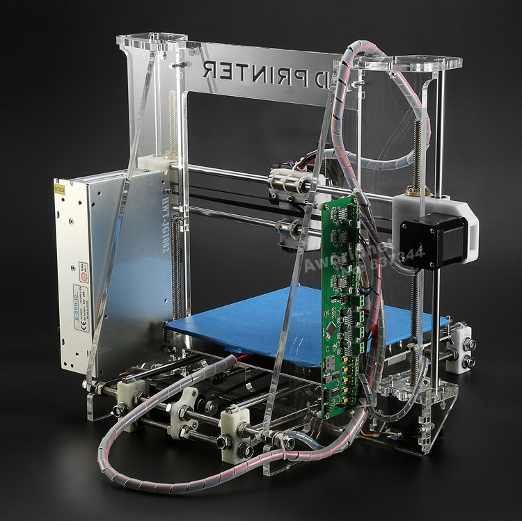
So, as I wrote above, I got an Ender 3 Pro printer from Creality.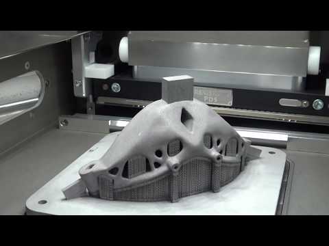 Entry level printers from this company are among the most popular in the United States, due to good quality, both manufacturing and printing, low prices, and wide community support. Well, and I will not hide it, a great "deal" in our local Microcenter-e (this is a computer store located in Cambridge, MA) played a significant role: they were sold for $99 at a promotion, plus a $10 off coupon for filament (a plastic thread for print), which I managed to use as many as three times 😊. For the printer itself, I also had to ride a couple of times to the store: they diverged, in the words of the classic, “like meat pies at a vegetarian lunch”!
The printer comes neatly packaged as a DIY kit.
However, assembly, greatly facilitated by the video (paper instructions are also useful, but the video is much more visual), attached to the micro SD-card that comes with the printer, will take you no more than an hour or two maximum, after which the printer is literally ready to work ! What you should pay attention to when assembling: this is the location of the "limit switch" of the vertical axis (Z) - he strives to stand in, as it were, the place allotted for him, but everything is not so simple. This sensor is very important (however, they are all important, so it is important to follow the assembly instructions punctually, and understanding what exactly you are doing), because it determines the distance of the print head nozzle (hot end) from the print bed (heated / print bed).
The main elements of the 3D printer
And this distance is very important: if it is large, you will not be able to correctly calibrate the position of the print head, and if it is too small, then the print head may damage the surface of the printing plate. As I did (however, this can be found in a bunch of online manuals, and, probably, on the official website in the FAQ - but I did not look): after assembling the printer, I set all four calibration "lambs" under the printing table to a "relaxed" state , and the “endstop switch” of the Z axis was fixed at a deliberately greater distance so that the print head (hot end) was guaranteed to be at a distance from the printing table. Then I turned on the printer, and chose the command from the “Auto Home” menu. After the printer set the head to the “home” position, I turned it off, and rotating the motor (stepper motor) of the Z axis by hand, as well as carefully moving the “limit switch”, I ensured that the “click” of the “limit switch” (and this means the sensor is triggered) was heard by touching the head of the table surface, after which he fixed the “limit switch” tightly with a key. Then, taking a sheet of ordinary paper, and rotating the “lambs” of the calibration screws, as well as moving the print head across the entire surface of the desktop, he ensured that it moved, slightly “scratching” the sheet. But, unfortunately, such a “cold” calibration will not be enough for a successful print, so I will recommend the “hot calibration” or “battle check” method. Here in this video you can see how the calibration process takes place, as well as download the necessary files (the link is in the video description). There is also a link to print profiles for Ender 3 Pro - I also recommend downloading them (and what they are for, I'll tell you later).
After assembly and calibration is complete, your 3D printer is ready to go! If you stocked up with a kilogram coil with PLA plastic in advance (PLA filament, more about the plastics used for printing will be in the next part), then you can safely install it, and if not, then a small skein of plastic filament comes with the printer (but it’s better to buy a coil right away, because filament is also required for calibration!). On the micro SD card that came with the printer, there are several models ready for printing - these are files with the extension .gcode (G-code is a programming language for CNC devices, understood by most 3D printers. Don't worry, you won't need to learn features of this language - special programs called "slicers" (slicer) will take care of this for you, so that you load the filament (plastic thread from the spool) through the extruder (extruder, filament feeder into the print head) through a small hole in the extruder ( pressing the clamp with your hand and directing the thread through the feed tube, move the thread all the way into the print head), insert the micro SD card into the printer, and select the model in the form of a .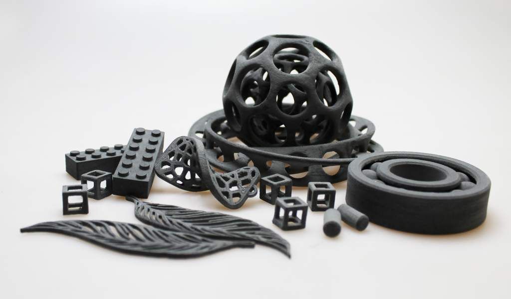 gcode file, you can safely start printing!
Models in gcode bundled with Ender 3D Pro
You can print anywhere - in the office, in the dining room, in the living room, in general, where you assembled the device. Later I will tell you where it is better to place the printer on a permanent basis, but any place is suitable for test printing - there will be no unpleasant smell or much noise.
But here's one thing you need to consider beforehand: 3D printing takes a hell of a lot of time! Even a small model can be printed for several hours (and a large one for several days!), Depending on the selected slicer settings, speed and printer settings. So, when starting to print, take this into account - the printing process, of course, can be paused (and then resumed), but for a start, I would recommend bringing the process without interruptions - well, to see a real good result, and feel confident in on their own, as well as the capabilities of the printer.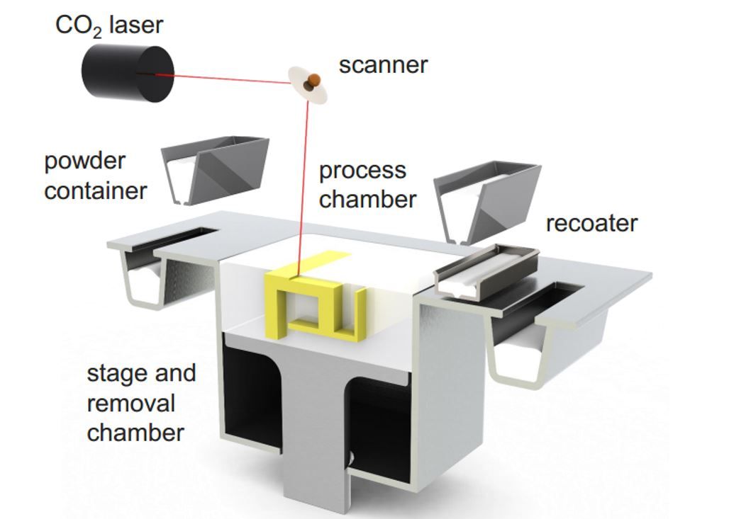
It should be noted that Creality uses the open source Marlin software as the firmware for its entry level 3D printers, but unfortunately pre-installs a very outdated version. If you are a programmer, or just “on you” with a computer for a long time, then it will not be difficult for you to assemble the latest version of Marlin yourself, for example, through VSCode, and then “flash” it via an SD-card (you just need to clear the card, and copy the release file with the .bin extension there). Otherwise, you can use my build - download, unzip, copy to a blank SD-card, turn off the printer, insert the card, turn on the printer. After a short time, the new firmware will be installed on your Ender 3 Pro (other printer models may require different builds). However, you can postpone this option for later - the printer is ready to work right out of the box.
Here I want to mention a few more useful printer improvements that will be useful for a beginner (however, these improvements are optional).
First, I recommend that you install and connect the open source OctoPrint software to your printer - you will need a Raspberry Pi with a camera for this. I used a cheap Raspberry Pi Zero W (with built-in WiFi) which, while not officially supported, works great. OctoPrint will add to your entry level printer far from entry level "features" - the ability to remotely control and manage the printer via a web interface, as well as from a great smartphone application.
This application is actively developed and well supported, has a very large and friendly community; many useful features are implemented either directly out of the box or using plugins; the documentation is also extensive and comprehensive. Installation, as well as connection to the printer, are extremely simple: download the sd-card image, edit the configuration file (specify the credentials of your WiFi access point), copy it to the card, connect it using a micro USB ↔ micro USB OTG cable to the printer - and profit!
My RPi Zero W with camera and temperature sensor connected to Ender 3D Pro
Secondly, I recommend that you immediately get spare surfaces for printing (build surface plate, this is a removable surface that is installed on a heated bed (heated bed), and on which, in fact, printing takes place). The printer comes with a "standard" flexible magnetic surface, and I assure you: you'll have to get a new one soon enough! So, it's better to take care in advance, because their cost is low, on Amazon they ask for $9.99 for a pack of two. You can also “upgrade” to a glass plate (it costs a little more), it has both its advantages and certain disadvantages, I will list them briefly. Advantages of the stock flexible magnetic plate: thanks to the magnet, it is easy to attach and remove from the heating bed for cleaning, thanks to the flexibility, it is very easy to remove finished models. Disadvantages: the plastic coating, on which, in fact, the printing takes place, is quite easily damaged and deformed both by the “regular” printing process itself and by the print head, in case of incorrect calibration, as well as by excessive heating of the heated plate - in general, a short-lived part. But, due to its low cost, it may well (and should!) be considered as a “consumable”. The advantages of glass plate include greater durability, cleanliness and "adhesive" properties of this surface.
 Disadvantages: slightly more difficult to attach to a heated bed (usually it is recommended to use ordinary office clamps for this, but personally I don’t recommend it because of their size; it’s much easier to buy special small clamps, they cost a penny on Amazon), and the difficulty of detaching printed models - you can't bend a glass plate. By the way, glass plates are also very inexpensive;
Thirdly (albeit looking ahead a bit), I would like to recommend this small "update", namely, glue for "sticking" models. Such glue is cheap (for 6 "sticks" they ask for $ 13), it is completely environmentally friendly, unlike popular home-grown products (there will be a story about them later), it is washed off with ordinary water, it does not smell. When using it, there are also a couple of “nuances”: you should not apply it to a cold surface, and you should not apply too little, because it will lose its adhesive properties when heated, and requires some practice in determining the optimal amount, but the ease of use of glue more than covers everything this is.
Now I want to share my thoughts on where is the best place to place your new 3D printer you just bought. 3D printing is actually a “heat-loving” process, so it is highly desirable to place the printer in a heated room with room temperature (at least 20 ° C - 3D printing traditionally uses temperatures in degrees Celsius - well, or 70 Fahrenheit). As I already wrote, at the very beginning, when printing with some types of filament, for example, PLA, there are no unpleasant odors, and the noise from the fans is comparable to the noise of the fans of a gaming desktop or laptop during a fancy 3D game. Those. in the absence of a special room (workshop in the basement or garage), it is quite possible to install a printer in the office, or even a children's playroom, or family room. What's more, there is a way, by purchasing a printer enclosure, to reduce or even eliminate both possible odors and likely noise. I will talk about this in more detail later.
I personally installed the printer in my "workshop" in the basement.