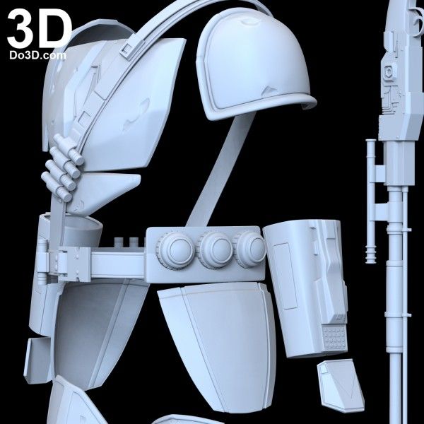
3D print heads
3d Printed Head - Etsy.de
Etsy is no longer supporting older versions of your web browser in order to ensure that user data remains secure. Please update to the latest version.
Take full advantage of our site features by enabling JavaScript.
Find something memorable, join a community doing good.
(1,000+ relevant results)
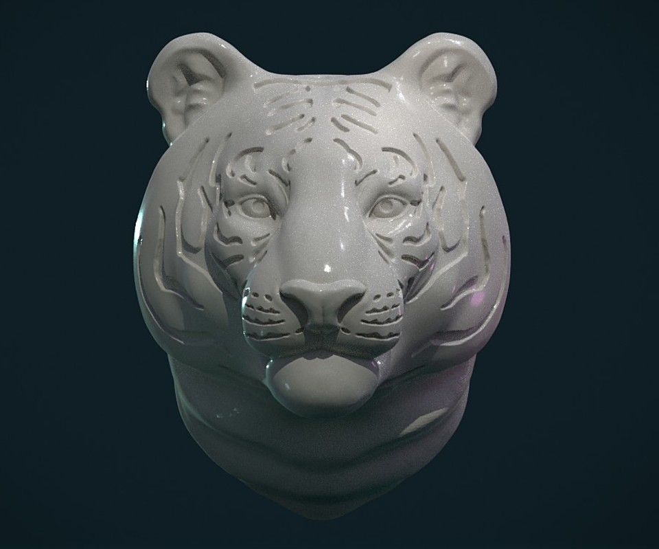
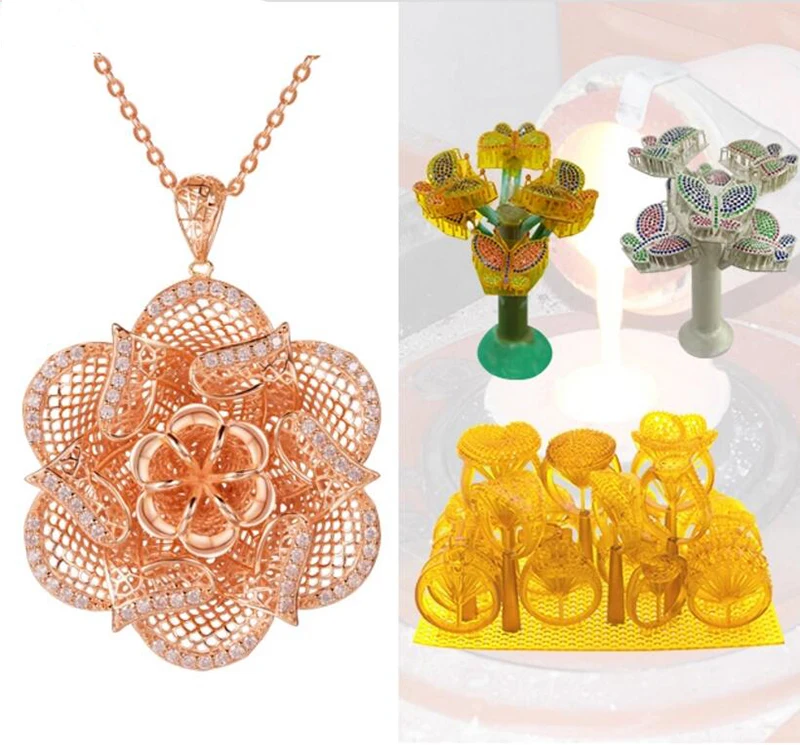
Head best 3D printing models・Cults
Bust of Pepe
€3. 43
Head acessory Saiki - Saiki Kusuo
€1.83
Head Model
€0.97
heads caps 3D print model
€44
pitbull dog
€0.50
HEADS HELMETS 3D print model
€39
Batson Ross - Headsculpt for Action Figures
€4.75 -50% €2.37
scull
€11
vase pencil pot head woman scult love
€1
vase pot face woman sculture design deco metal
€1
STEEL CYBORG HANDS helmets for new Heresy
€3
Eddie The Head Samurai Senjutsu
€22.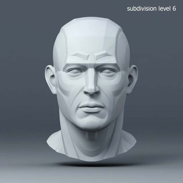 81
81
scull 3d model
€10
SKULL HEAD
€2 -50% €1
Faceless hood head
Free
T-REX Desk Lamp
Free
Alien Heads Keychain - portachiavi teste alieno
Free
Fox Head and Paws
€1.15
Dragon Head + Feet
€1.15
Jacky - Headsculpt for Action Figures
€3.75 -50% €1.87
peacemaker belt
€5
Sappho's Head - Refined
Free
Shower Head MK1
Free
Long Haired Supes - Headsculpt for Action Figures
€4. -50% €2.37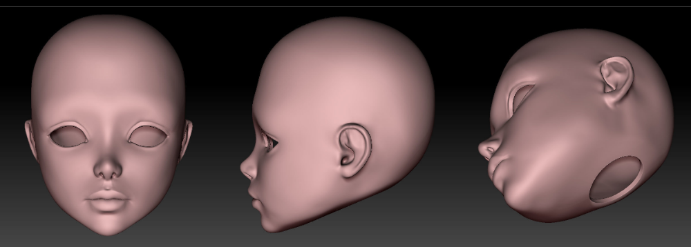 75
75
Panchmukhi Hanuman
€42.56 -85% €6.38
Medusa pendant
€0.97
iron man zombie
€9.62
Spooky Lords Of Midnight HELMETS FOR NEW HERESY
€3
CUSTOM ARES HEADSCULPT
€6.86
CUSTOM NICK FURY HEADSCULPT
€6.86
Fallout Vault Boy Charisma Bobble Head
Free
POCHTA KEYCHAIN
€0.76
POCHITA
€0. 76
76
Cylon Head Helmet Car Emblem Badge Logo for Scion Toyota & Others Battlestar Galactica
Free
Speedster and Reverse Speedster - Headsculpt for Action Figures
€4.75 -50% €2.37
Hercules Bust STL File
€3
Lion Head - 3D STL File for CNC
€8
Low Poly three-sided mask
€3.80 -50% €1.90
chainsaw man power horns
€1.22
Fellbeast Trophy
€1.47
Mascara de Marshmello
Free
Ostrich head
€18.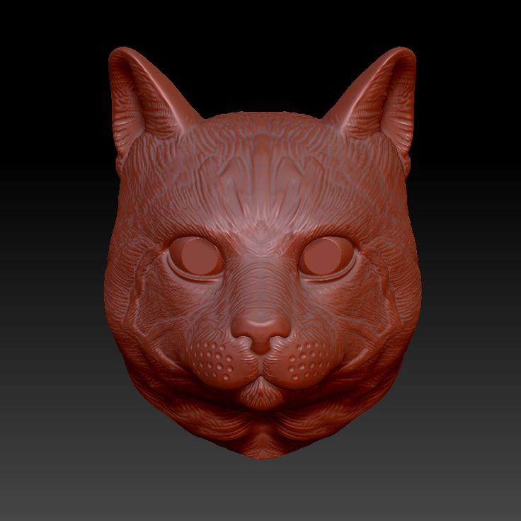 51
51
Hulk head for action figure
€4.90
Brain Trophy
€9.16
Oni Collection Head Collection for Action Figures
€15
Ideal mask for Halloween day of the dead events.
€6.50
Troll head sculpt from God of War game
€12.24
Batsy Bale - Headsculpt for Action Figures
€4.75 -50% €2.37
3D printer print head
The 3D printer print head is called an extruder. The name reflects the principle of operation: the print head extrudes the thermoplastic through a special nozzle. Drawing an analogy, glue guns common in everyday life, syringes with sealant, tubes of toothpaste, and finally, operate in the same way.
As a rule, filament (filamentary) thermoplastics such as ABS or PLA are used for 3D printers. What to choose for printing - see the article: Choosing plastic for printing on a 3D printer.
However, sometimes more exotic plastics are used, for example, you can print with nylon on a 3D printer, in fact, cheap trimming line is used.
Despite the variety of 3D printers, their printheads are made on the same principle and do not differ much from each other. For example, a small Myrwell 3D pen is actually a full-fledged extruder enclosed in a body that is comfortable to hold in your hand.
Extruders in general and direct feed extruder in particular can be divided into two main blocks:
- cold-end
- hot-end (literally "hot end") - a nozzle with a heater.
Cold-end , in turn, consists of a gear driven by an electric motor (direct or gear connection) and a clamping mechanism.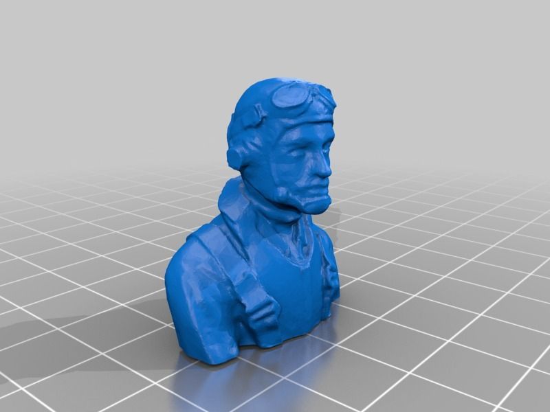 A rotating gear removes the filament from the spool and passes it into the heater, where the thermoplastic changes its state of aggregation from solid to viscous under the influence of high temperatures, which allows it to be extruded through a nozzle and given the desired shape.
Hot-end is made of aluminum or brass (due to the high thermal conductivity of these metals). The heater consists of a spiral (nichrome wire) and a pair of resistors, as well as a thermocouple for temperature control.
During operation, the hot-end heats up because the melting temperature of the plastic is high enough. At the same time, the rest of the system must remain cold throughout the entire operation cycle. To prevent premature melting of the thermoplastic, there is a heat insulating insert between the "hot" and "cold" ends. Moreover, the extruder is sometimes equipped with an additional heatsink with a fan.
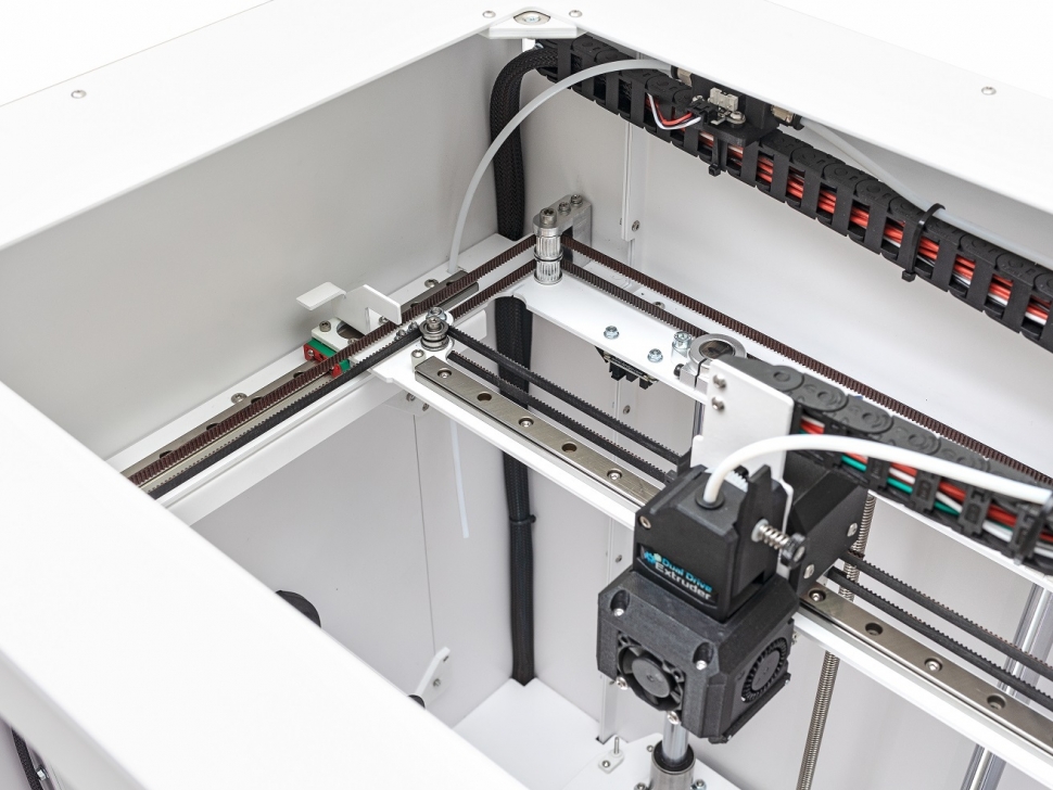
Another type of printhead is bowden extruder extruder (English Bowden extruder ). They differ from direct filament extruders in that the hot-end and cold-end components are spatially separated: the heater and nozzle are located on the print head, and the feeder is located on the frame of the 3D printer.
The filament is fed through a long Teflon tube, however, if there is no Teflon, then an ordinary plastic one is also used, but then a more powerful engine must be installed, as there is frictional resistance in the supply tube.
The tube is needed so that the plastic thread does not bend and is fed into the hot end with decent pressure and speed.
Here is a small video review of the bowden extruder - the video shows a modified version for a delta 3D printer.
The advantage of such a conceptual solution is the reduction in the dimensions and weight of the print head, the minus is that the supply of thermoplastic to the nozzle becomes not as reliable as in direct feed extruders.
Important details to consider when choosing a head for your homemade 3D printer.
Material . Extruders can be equipped with either 3D printed or cast components. It should be borne in mind that the cast parts are stronger, which is especially important if we are not talking about the case, but about those parts of the system that are constantly under stress. Printed components are cheaper, but their strength is an order of magnitude lower than that of cast ones. On the other hand, you can always print spare parts for the 3D printer extruder yourself.
Filament supply . The quality of the feed mechanism determines the continuous supply of filament to the heater, which means it ensures uninterrupted printing. The fact is that the plastic for printing on the way to the nozzle can get confused. If the electric motor has sufficient power, then even the presence of small entanglements will not affect the operation of the entire system.
Feed roll type .
Another problem that may occur is thread slippage due to poor grip on the feed roller. This is true when printing with nylon filament on 3D printers designed to use ABS or PLA thermoplastics, since the feed wheels are made with smooth teeth here. In such cases, it makes sense to use a roller with sharp teeth.
Extruder nozzle size . Printheads are equipped with nozzles with a diameter of 0.4 - 0.5 mm, or 0.2 - 0.3 mm. It all depends on the context in which you plan to use the 3D printer. If the detail of the drawn objects and the increased accuracy of their positioning are important, nozzles of smaller diameters should be chosen. Here it should be borne in mind that the smaller the size of the nozzle, the greater the likelihood of clogging, and the more powerful the electric motor is needed to extrude the thermoplastic. In other cases, extruders with a standard nozzle size of 0.5 mm will be the best option.
Currently, there are several models of 3D printers with two and three extruders (MakerBot Replicator Dial, 2X).
The dual extruder printers are useful for creating support structures and printing two-color objects because they can use two types of plastic. One of them can be dissolved in ordinary water and used to print support parts, and the second extruder is filled with already working PLA or ABS thread.
The disadvantage of dual extruder printers is that both extruders are attached to the same print head, and therefore simultaneous printing is defective: the printer has to use the extruders separately, as needed.
However, there is also a method of simultaneous printing - "Ditto printing". In this case, the extruders work in parallel and create copies of the same object. There are also some downsides here. The technology has a very limited use, since it produces only small one-color objects, or large two-color objects with a repeating pattern.
In addition to these problems, 3D printers with multiple extruders have two more significant, but standard for new products, disadvantages - price and complexity of setup.
The technology is still "raw", which manifests itself in a decrease in the speed of the device due to an increase in the dimensions and weight of the print head. In addition, during operation, a nozzle that is not involved in printing, at best, leaves traces of the filament on the surface of the drawn object, and at worst, it can deform it.
The versatility of the 3D printer's print material supply system gives free rein to the imagination in choosing the composition of the printing mass. You can use not only thermoplastics, but also clay, plasticine, melted chocolate, silicone and other pasty materials. The only caveat: extruders in this case are equipped with a special syringe, which is filled with the above substances. The syringe rod is driven either by compressed air or by a stepper motor.
Kinematic systems for moving the 3D printer head
In the production of various functional products such as machine parts and structural elements, quality assurance issues are of particular importance. So, due to the layer-by-layer formation of a printed product, stripes form on its surface. The stepped look is best seen on curved and curved surfaces. It becomes more pronounced as the layer thickness increases. Stepping may not affect the strength of the printed product in any way, it most often only increases its roughness. However, if the product does not require a low level of roughness per se, but only the appearance (for example, if we are talking about instrument cases), you can resort to a simple finish of the outer surfaces. Significant dimensional errors and distortion of the shape of products that can be tolerated during printing are a much bigger problem. In the most common 3D printers using layer-by-layer fusing technology (FFF, Fused Filament Fabrication), two main factors are of decisive importance: temperature shrinkage of the material and positioning error.
The shrinkage of the printed object is determined by the physics of the process: the molten material is squeezed onto the platform layer by layer and solidifies in the form of the final product, and in the process of cooling from the melting temperature to room temperature, it seems to shrink. Different materials can shrink more or less, but this process is always uncontrollable. In some cases, it can be assumed that shrinkage occurs uniformly in all directions by a certain percentage. Based on this assumption, corrections can be made to the control program (G-code) that can partially compensate for the shrinkage error.
An equally important role in ensuring accuracy is played by the positioning accuracy of the working element of the equipment, i.e. the print head of the printer.
To date, many options have been proposed for building a system for moving the print heads of 3D printers, however, systems based on belt drives are most widely used.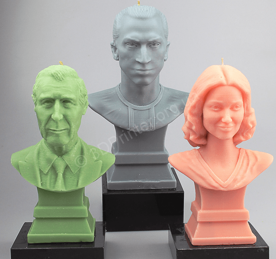 This is due to the fact that the load acting on the print head during operation is relatively small (unlike metal-cutting machines, printers do not have such a powerful disturbing factor as cutting forces), so such kinematic schemes provide sufficient rigidity. At the same time, they are characterized by simplicity, economy and high speed of movement, which positively affects productivity. However, at the moment, the factors affecting the accuracy of the positioning of the print head in such systems remain poorly understood. There are no practical recommendations on choosing the configuration of the kinematic scheme and the dependence of positioning errors on the operating parameters (mass of the print head, dimensions of the construction area, belt pretensioning, gaps in movable joints, etc.) of the 3D printer.
Among the known variations of kinematic systems based on belt drives, one of the most common is the H‑Bot single circuit. It has a single belt in the form of the letter "H" and is driven by two motors ( fig.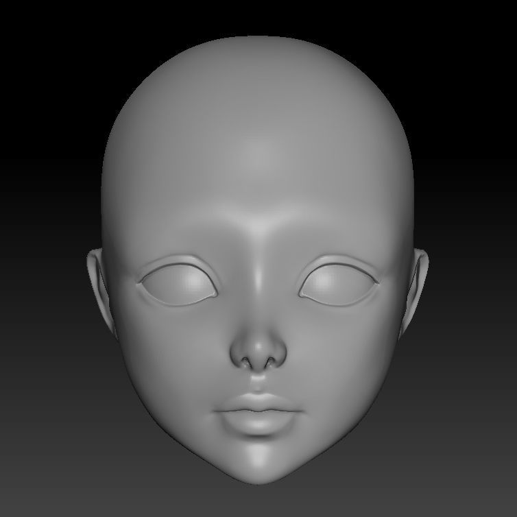 1 ). A small number of moving elements in this circuit reduces the inertia, which positively affects the positioning accuracy. It also increases due to the fact that when the motors are rotated by 1 step, the print head travels a linear distance equal to half a step. However, in this system, the unidirectional rotation of the motors required to move the printhead along the X-axis results in multidirectional forces that cause the transverse rail to skew relative to the longitudinal ones. The non-perpendicularity of the guides leads to the appearance of a gross error in the shape of the final product - for example, an object with a rectangular section will take the form of a parallelogram. In addition, the fastenings of the transverse guide to the longitudinal ones suffer from a repeated cycle of rectification skew, and the system resource is reduced.
Fig. 1. Kinematic movement system H‑Bot
In it, the use of two drive belts balances the impact on the moving elements, thereby maintaining their correct geometric arrangement.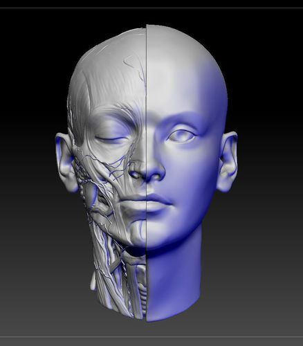 The system uses more bypass rollers than the H‑Bot system (2 more). However, in this scheme, it becomes necessary to ensure equal pre-tensioning of both circuits. In the event that one belt is tightened more than the other, with unidirectional rotation of the motors, as in the H-Bot scheme, a pair of forces appears applied to the transverse guide. The resulting moment of forces rotates the movable unit in the XY plane, this causes a violation of the perpendicularity of the guides and also leads to positioning errors and accumulative deformation of the elements of the movement system. To avoid cases of belt intersections, their contours are located in different planes - this leads to additional bending moments on the print head carriage.
Fig. 2. CoreXY Motion Kinematic
Compared to H‑Bot, the dual circuit motion system has less dynamic error caused by belt stretching during print head acceleration and deceleration: the presence of two parallel belt branches doubles the rigidity of this oscillatory system.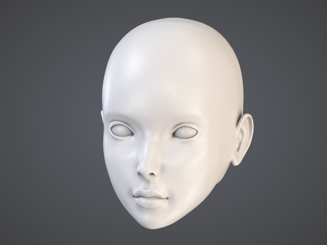
0021 fig. 3 ). This moving device has two belt circuits. The primary circuit belt is fixed on both sides of the carriage with a single guide roller and performs the function of moving the head along the X axis. 3. Kinematic movement system Markforged
The same circuit is driven when moving along the Y axis, but in this case, the second circuit belt is also driven, attached to the movable unit. Despite its simplicity, the scheme combines the disadvantages of both previous schemes - it requires equal belt tension and, at the same time, regardless of the tension, it tends to rotate the movable unit during unidirectional rotation of the motors. This scheme is not widely used among manufacturers of additive plants.
Another kinematic system in which each motor is responsible for moving along its own axis is the Ultimaker system. In it, the print head is driven by a transverse guide, which is fixed in the transverse blocks and slides along the central longitudinal guide, fixed in the longitudinal blocks.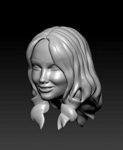 This kinematic scheme has high structural rigidity and low inertia of the print head. The system also includes closed loop belts, which in theory should provide equal belt tension. These characteristics have a positive effect on positioning accuracy. Nevertheless, the scheme is sensitive to the initial mutual setting of the guides, the error of their relative position is reflected in the shape of the printed products, similar to the skew of the movable unit in previous systems. The disadvantages of the Ultimaker circuit include a complex implementation and high quality requirements for linear motion components.
Fig. 4. Ultimaker Kinematic Handling System
There are other belt driven motion systems that have become less common due to significantly greater complexity or more disadvantages.
In the production of its own 3D and 5D printers (Stereotech 320 and Stereotech 520 ( fig. 5, 6 ) Stereotech uses its own patented STE HeadMotion print head movement system ( fig. 6, 7 ).
Fig. Fig. 5. Stereotech 3D printers: Stereotech 520, Stereotech 320
Fig. 6. General view of the Stereotech 320 3D printer in a housing without a top cover with a kinematic system STE HeadMotion
The print head movement system includes one transverse and two longitudinal rail guides. The longitudinal guides are rigidly fixed on the base in the direction of the Y axis, the transverse guide is located along the X axis and is connected to the longitudinal ones through the carriages. The print head moves with two drive belts, as in the CoreXY scheme, to increase the rigidity of the drive system and reduce the inertial error. The ends of the belts are fixed to form two connected contours on the print head carriage. The symmetrical arrangement of the contours compensates for bending moments on the bearings and guides of the moving parts of the system.
To solve the problem of ensuring equal belt tension in the circuits, a tension equalization unit is included in the device.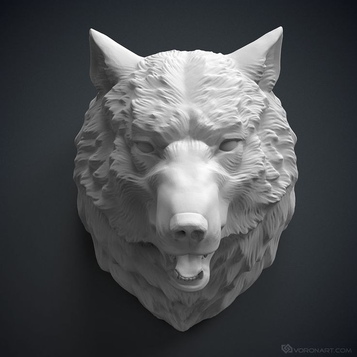 It is a lever with two rollers at the ends (each of which is part of a separate circuit), hinged on the base with the ability to rotate in the XY plane, and works on the principle of a swing. When a difference in tension forces appears in the circuits, the lever turns, the rollers move, and both circuits return to equilibrium. To dampen vibrations, dampers are installed at the ends of the lever ( fig. 7, 8 ).
Fig. Fig. 7. STE HeadMotion kinematic movement system with tension force balancing unit
Fig. 8. Calculation diagram of the tension force equalization unit
The movable unit with a transverse guide is made in the form of a single portal to increase the rigidity of the device, which also has a positive effect on positioning accuracy.
The motors are mounted on the base of the printer to reduce the mass of moving parts and reduce inertial moment.