3D print electronic enclosure
Benefit from custom electronic enclosures
3D Learning Hub
See all categories
Contents:
- Introduction
- Creating electronic devices with more scalability
- Advantages of 3D printed enclosures
- Developing your own custom electronics enclosures
Introduction
Creating custom electronic devices with more scalability
Creating electronic devices comes with its challenges. How can the creation of electronic enclosures participate in the development of your electronics project and in the growth of your business? Never forget about the advantages of better scalability and adaptability for your electronics enclosures. While creating these electronic devices, you must meet changing market demands with unbeatable lead-times thanks to an optimized and scalable manufacturing process. Making the most of Just-In-Time manufacturing and getting the parts you need when you need them might also be a huge advantage for your business.
Additive manufacturing has a lot of advantages to offer you in the electronics sector. Let’s take the example of the plastic electronics housings. Just on this part, 3D printing has a lot to offer. Implementing additive manufacturing in your process is a solution to speed up your processes and gives the possibility to be more reactive and at the same time, more competitive. But that’s not all! 3D printing is also giving you the opportunity to be more innovative and improve your enclosures designs.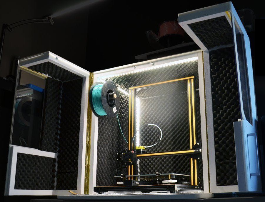 This way, you will be able to create plastic PCB enclosures perfecTly adapted to your projects.
Advantages of 3D printed enclosures for engineers and designers
Adaptability
The freedom offered by additive manufacturing has almost no limits. Creating snap fits, interlocking joints, threaded fasteners, and living hinges are all possible when 3D printing enclosures. Adapt your housings with all the functionalities you’ve envisioned for it. 3D printing gives access to a design flexibility injection molding just can’t offer. Indeed, with a mold, you won’t be able to change its design to make modifications to your final parts. If you need to modify your project, then you will need to start from the beginning and re-do the whole process again.
With additive manufacturing, it’s different: you only have to modify your 3D file, it won’t interrupt your manufacturing process at all. More reactivity in your process means you can adapt to your immediate needs without losing time and money.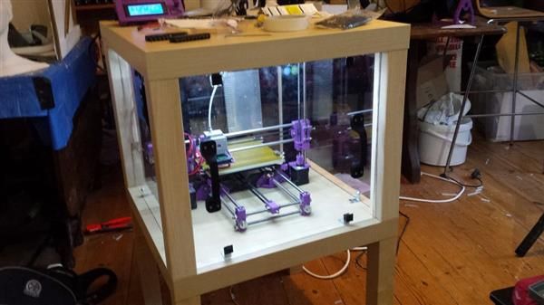 Using 3D files with 3D printing, you don’t have to worry about the lifetime of the enclosure design, your process just become more and more flexible. You will have the opportunity to implement all the changes you will need when you need them.
Moreover, mass-customization is a great benefit of additive manufacturing. You can adapt your file to the needs of your customer. It won’t be more expensive to manufacture several iterations of your enclosure using 3D printing!
Innovation
Additive manufacturing will offer you the opportunity to innovate and develop your projects. While using 3D printing, you can think about what you want to create, and not only what you can create, considering the traditional constraints of manufacturing. Feel free to experiment and innovate using cutting-edge technology such as additive manufacturing.
You can take into account all the functionalities of your part and integrate them directly into your device.
Speed your processes
Speeding your processes will help your business grow.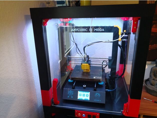 When you create your electronic device, the design and the ergonomy of the enclosure are as important as the features. To fill this important requirement, you can count on the ability of 3D printing to create complex shapes very quickly. 3D printing is the fastest prototyping technology because it allows to create unique prototypes without any mold which means that the price of the part is low.
With 3D printing, the price is not driven by the quantity but by the amount of material used. With several iterations of the same enclosure, 3D printing is a much more reliable and sustainable manufacturing method than traditional ones. Thanks to a 3D printed prototype, it is possible to check the ergonomy, the aspect but also the fit of the internal components or the accessories. With a variety of 3D printing materials, it is also possible to have a look at the final material aspect and to check the assembly.
Additive manufacturing also appears to be the perfect manufacturing method for the production of plastic enclosures. If you need customization or just-in-time manufacturing abilities, then there is no doubt about the benefits of this technology for your business.
Developing your own custom electronics enclosures
What 3D printing material should you choose?
What is the best enclosure material? To develop your project and start creating your 3D design, you will have to choose your material and take into account its design guidelines. If you are using a filament 3D printer, then PLA, PETG, or ABS become options to create your enclosure. But your electronic project might present some requirements and better mechanical properties to create an even more durable 3D printed enclosure.
Plastic electronic enclosures can be developed using additive manufacturing with adapted materials. To create these plastic enclosures, 3D printing materials such as Nylon PA12 or Nylon PA11 will be especially suitable for your project. These are two cost-effective material options that can be used to manufacture your prototypes, small or big series.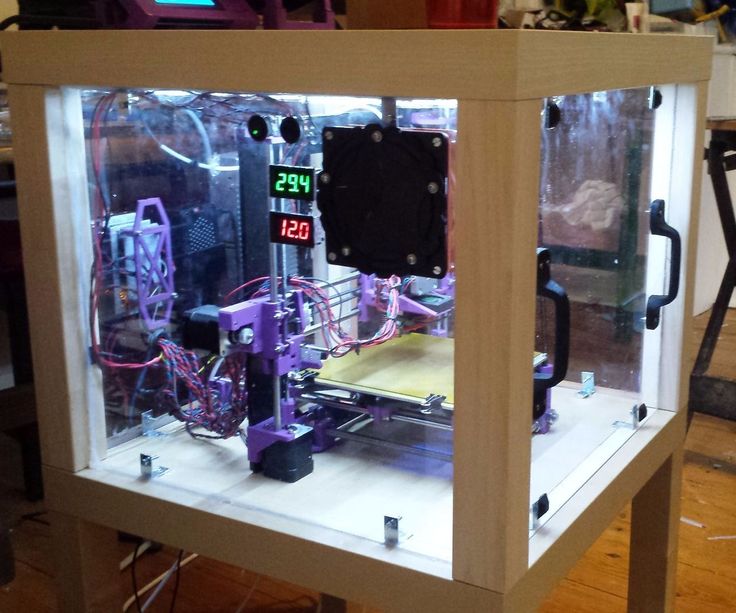
How to design enclosures for 3D printing?
It is really helpful to design the component around what you want to enclose before modeling the enclosure. In that way, you can place the components, check that everything fits and it will be easier to determine the clearance for the connectors or the cables afterward. To be sure that your components will fit, we recommend keeping a 0.5 mm clearance between components and 3D printed features.
Access to the component
The first thing to think of when designing an enclosure is what you will put in it and how you will access it. If you do not need to have access to your components, you can design specific fastening components or use adhesives to seal your enclosure permanently.
In the case where you want to have access to your components, there are many closing systems you can use:
- Semi-rigid lugs
- Sliding faces
- Screws
- Classic and Living hinges
- Assembly
Lugs, cut-outs and lips, help with the assembly and parts alignment. Moreover, these features are great to strengthen your enclosure if you respect the minimum dimensions of such features. Check the design guidelines of your chosen material for more information. Learn how to connect two parts with 3D printing, in our dedicated article.
The solidity of the 3D printed enclosure
The wall thickness of your enclosure is a major thing to consider. It determines the weight, rigidity, solidity, and possible applications of your enclosure. Even if our machines can print smaller details and walls, we recommend you to respect a minimum wall thickness of 2 mm. This value ensures a structural solidity with a very light weight. Once again, check the design guidelines of your material to adapt this thickness.
Be careful however depending on the length of your enclosure, a 2 mm wall thickness can give a certain flexibility to the walls and can cause some shrinkage.
A fillet is a key feature in 3D printing because hard angles may not be properly 3D printed. Fillets in enclosures are really important both in the inside and the outside.
Fillets avoid sharp angles and reduce the stress
Outside of your enclosure, soften your corners with very small fillets (1 or 2 mm).
Inside your enclosure, the corners can be strengthened with bosses and fillets. A very small radius facilitates 3D printing and reduces the stress concentration on corners.
Bosses with fillets on the inside allow to reduce the stress around a hole
3D printing enclosures: quality and accuracy
If your design contains screw holes or fastener clearance holes, be sure that your material is accurate enough. With our 3D printed plastic, the accuracy is very high but to obtain more precise holes, it is recommended to drill or tap them afterward with machining tools.
Slightly expand the diameter of screw and fastener clearance holes to obtain better results
On the other hand, reduce the diameter of the holes where you want the screw or fastener to bite into the case
To learn more about threading in 3D printing, you can check this article.
In enclosures, small walls and thin features are often added to keep components in place. These features have to respect the minimum thickness of your material but in addition, we suggest adding structure features like gussets or ribs that will give strength to your element and help it to be 3D printed correctly.
Gussets or ribs reduce stress, strengthen thin features and reinforce the case
Finally, remember that you can iterate really fast but it is also possible to go into production with 3D printing for your enclosures. Many of our customers have already tried our online 3D printing service to go into production for their enclosure
Related Topics
- Return to Top
Get the latest 3D printing news delivered right to your inbox
Subscribe to our weekly newsletter to hear about the latest 3D printing technologies, applications, materials, and software.
How to Design 3D Printed Snap Fit Enclosures
If you’re a product designer or an engineer, chances are you’ll need to make a custom enclosure at some point. This might be a simple container to keep small items organized or a fully functional 3D printed prototype to show stakeholders or test before moving to injection molding.
With CAD software and a desktop 3D printer, you can create a custom 3D printed snap-fit enclosure with interlocking parts in five easy steps.
White Paper
Looking for a 3D printer to realize your 3D models in high resolution? Download our white paper to learn how SLA printing works and why it's the most popular 3D printing process for creating models with incredible details.
Download the White Paper
Sample part
See and feel Formlabs quality firsthand. We’ll ship a free sample part to your office.
Request a Free Sample Part
Measure your electronic component (left). Begin your 3D model with basic boxes (right).
For this project, we’re going to make a case for a Pine 64, a single board computer (download the .STL file on Pinshape to follow along). This tutorial uses Solidworks because of its popularity in product design and engineering, but you can use a similar 3D design software.
First, use digital calipers or a ruler to measure your electronic component. We like to start enclosure designs by accurately reverse-engineering the PCB, measuring the board size, the location of mounting holes, and any ports or plugs that will need to be accessed through the enclosure. You might want to simply measure the overall maximum dimensions as a box, but it’s essential to know exactly where the main features are so that you can accommodate them. In Solidworks, reproduce these measurements as a grouping of basic boxes in a single part file.
In Solidworks, the enclosure is best designed as an assembly, with each half of the enclosure modeled as a separate part. Starting with the base half of the enclosure as a new part, the first important decision is to determine how much of a tolerance to have between the perimeter of the PCB and the enclosure. This depends on the 3D printing process you're planning to use to 3D print parts. SLA and SLS 3D printers are highly accurate, so you can tighten the tolerance to 0.5 mm without much risk.
A desktop FDM 3D printer may warp your design and lift it off of the print plate, so you should allow a larger tolerance of 1.5-2 mm to ensure that the PCB will still fit inside even if the walls are somewhat distorted.
Read our in-depth guide about FDM vs. SLA 3D printers to learn how they compare in terms of print quality, materials, applications, workflow, speed, costs, and more.
Add space between the perimeter of your electronic component and the enclosure (left). Build the walls of the bottom enclosure in your 3D model (right).
Our next step is to start cutting away the openings for the ports. One common mistake is that you will only cut away just enough material to expose the port connection, be it a USB or HDMI, without taking into account that many cables around the male connector can be quite bulky and need to reach into your enclosure to connect to the port (especially if the port is set in from the edge of the PCB, farther away from the enclosure). So it’s best to be generous with the port openings. An extra 2 mm all the way around is a good starting point.
Add extruded cuts and cutouts to the bottom enclosure to fit ports.
As you can see in the image above, we included extruded cuts, which go all the way from the top, and one cutout for a Micro SD card. The reason that some of the cuts reach the top is that the ports on the board stick out beyond the edge of the PCB, so in order to fit the PCB, we need to allow room for them to slide down. We will close some of these off with our top enclosure part, but you could choose to create a larger bottom enclosure so that the entire PCB and ports fit inside. Just be aware that you will have to push your connecting cables further inside the enclosure.
In general, the top enclosure mirrors the geometry of the bottom enclosure.
Now that you’ve completed the bottom enclosure, the top section is easy. The above image shows the effect of the parting line running around the perimeter between the two enclosure halves. The top enclosure has had the same treatment of cut details to accommodate some of the taller ports, as well as the addition of material to close off some of the gaps left by the bottom enclosure. We also added an optional sunken middle section.
White Paper
Designing for proper tolerance and fit lowers post-processing time and ease of assembly, and reduces the material cost of iteration. Download our white paper to learn more about tolerance and fit in 3D printing designing functional 3D printed assemblies.
Download the White Paper
With a basic internal cantilever snap, you can lengthen the amount of plastic engaging into the snap for a stronger lock.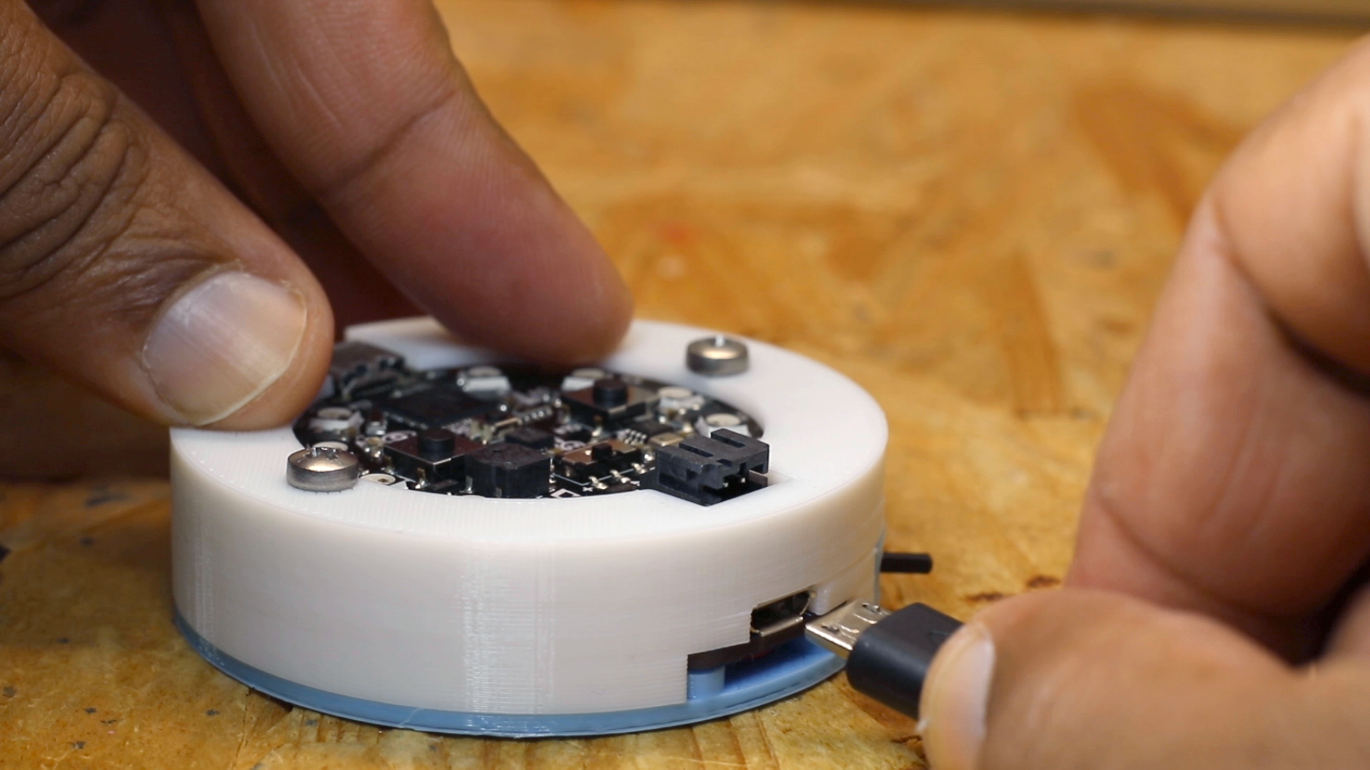
There are many designs for snap-fit components, but we opted for a basic internal cantilever joint. Above you can see the main details for the snap-fit design, which is exactly the same on both sides (male and female parts) of the enclosure. Depending on the space you have to work with, you can lengthen the small protrusion engaging into the snap cavity to create a stronger lock. In our snap-fit assembly, it's only 1.2 mm, but 2 mm or more would be much more secure. In this particular design, the pins on the PCB take up a lot of room, so the lock is designed to just squeeze in while providing enough force to hold the enclosure together. The cantilever joint is extruded 20 mm long, which adds to the strength.
This sectioned exploded view shows the snap details on each side.
Above you can see a sectioned exploded view of the snap details on the enclosure, along with the PCB showing the location of the pins (in black), which limit the size of the cantilever joint. Alternatively, instead of the snap cavity hiding inside of the bottom enclosure, you could cut this detail through to the outside, allowing your snap-fit joints to be longer.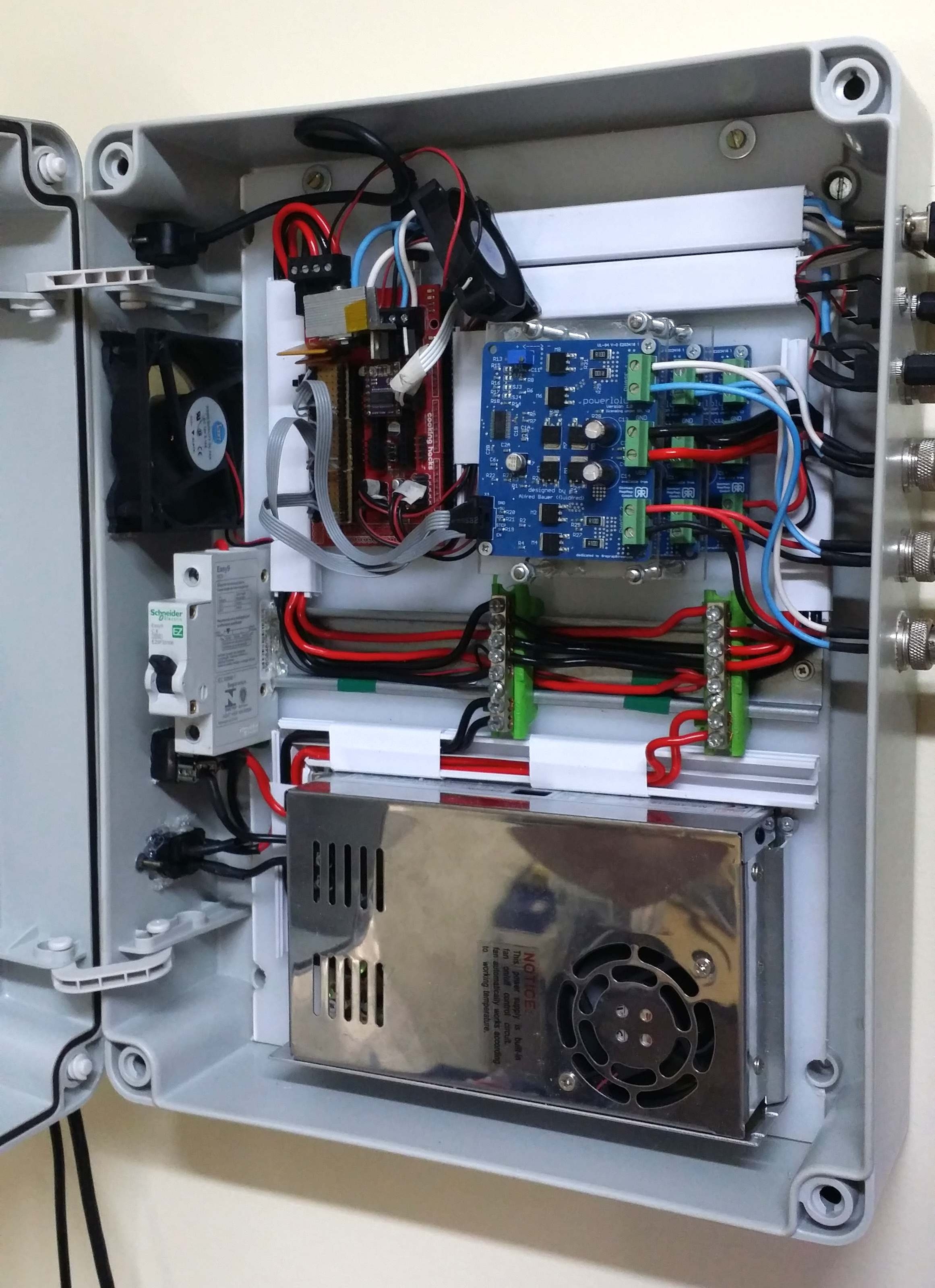
Lugs are small extrusions that slide within the opposite enclosure to secure the two halves.
Add lugs to your design to keep the two halves from sliding. Lugs are small extrusions that insert into the opposite enclosure. Because we created two snap-fit joints on opposite sides, you might need these on just the two blank sides. For this larger case, we put them in each corner. The material extrudes only 3 mm down, but this is enough to prevent movement on 3D printed interlocking parts.
This basic snap fit enclosure can be adapted for nearly any small electronic component.
While this might be enough detail for your project, a few added features can bring your 3D printed enclosure to life. For this design, we extruded some text for the Pine 64 name and details like the SD card location. We included the Pine 64 logo as a visual feature, but also to provide ventilation on the top since these boards can heat up. Plus, these details reduce the amount of 3D print material used.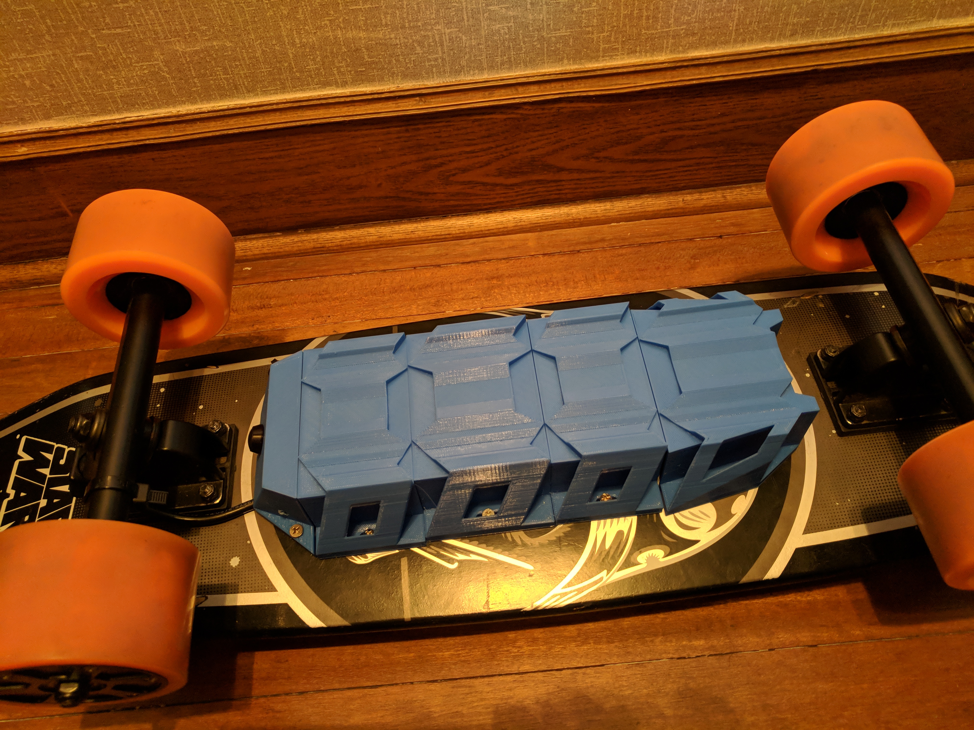 Finally, a couple of grip details where the snap-fit joints are located helps indicate where to press your fingers to open the enclosure.
The final design includes unique features along with the snap fit enclosure, ready to be 3D printed.
Webinar
Join our materials experts as they discuss how the incredible properties of PU Rigid Resins paired with the benefits of 3D printing are eliminating previous limitations of traditional polyurethane manufacturing. Take your 3D printed snap fit enclosures to the next level with two new, true polyurethane materials.
Register for the Webinar Now
SLA 3D printing offers a wide variety of engineering materials for creating accurate 3D printed parts and prototypes and help you reduce costs, iterate faster, and bring better experiences to market.
Want to see what you can create with a SLA 3D printing? We’ll ship a free 3D printed sample part to your office.
Request a Free Sample Part
how to optimize design and speed up production
Rapid prototyping
Experts recommend
Author: Viktor Naumov
Author: Viktor Naumov
Benefits of 3D Printed Cases | Developing custom electronics cases: what material to choose for 3D printing? | How to design enclosures for 3D printing | Access to components | The strength of the 3D printed case | Quality and precision | Order a 3D printing service
Implementing additive manufacturing can bring more value to your business than you might think. The production of electronics requires a lot of effort, but thanks to 3D printers, this process can be simplified. We will look at one particular detail: the body of an electronic device. How can it be improved and thereby optimize the entire production process? This will be discussed in the article.
Scalable Electronics Manufacturing
The manufacture of electronic devices is associated with certain difficulties.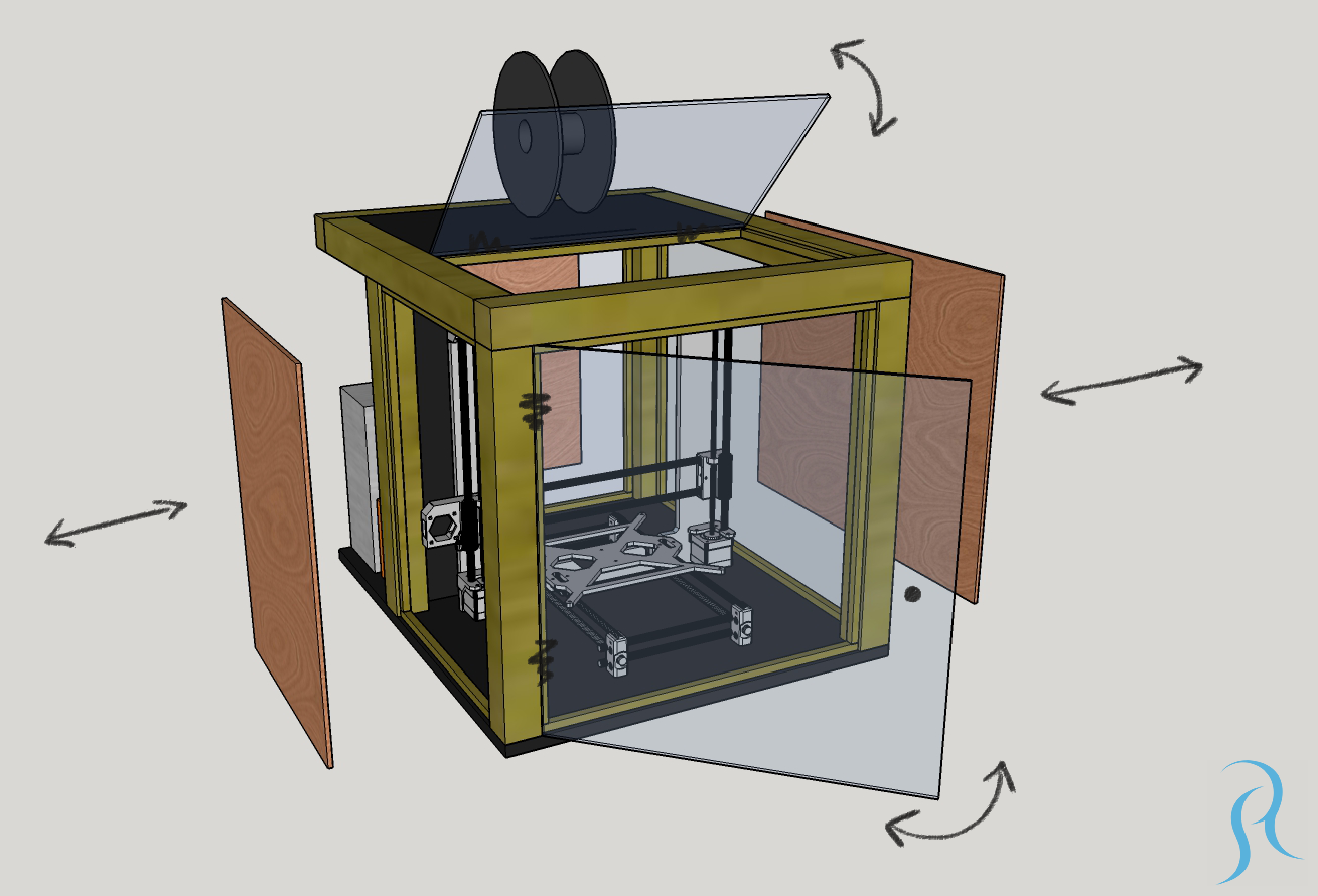 How can the creation of electronics cases affect the success of related projects and business as a whole?
See the benefits of scalable and adaptable enclosures. When designing electronic devices, you must keep pace with changing market demands, including record-breaking project turnaround times. This is made possible by an optimized and scalable manufacturing process. Implementing Just-In-Time principles in part manufacturing can also be a huge business benefit.
In the electronics industry, additive manufacturing opens up many opportunities. Consider the example of a plastic case. This is where 3D printing technology can bring significant benefits. The introduction of 3D printing is a solution that can speed up production processes and increase competitiveness. But that is not all. Additive technologies will also enable innovation and improved hull design.
iQB Technologies Experts Recommend Article: 14 Frequently Asked Questions About FDM Production Printing
Benefits of 3D Printed Cases
Adaptability
Additive manufacturing provides almost limitless freedom of action.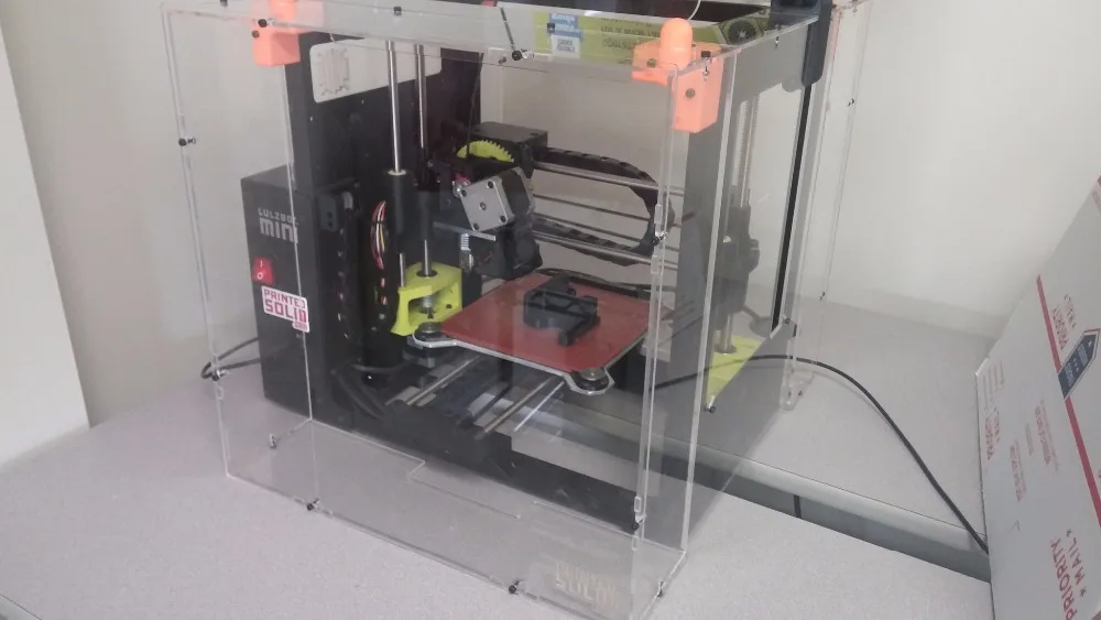 In the manufacture of cases on a 3D printer, it is possible to provide for latches, locking connections, threaded connections and flexible hinges. Thanks to thoughtful functionality, the case will become more versatile.
3D printing provides design flexibility not available with injection molding. Indeed, it is almost impossible to make changes to the design of the finished mold. If you want to change the project, you will have to start all over again.
With 3D printing, everything is different: you just need to make changes to the 3D file, which will not stop the manufacturing process for a minute. The ability to quickly adjust workflows increases production agility at no extra cost. Thanks to 3D files, there is no need to worry about the service life of the body structure or other part. Changes can be made at any time as needed.
Another significant advantage of additive manufacturing is mass customization. You can customize the work files according to the client's needs. Making several iterations of the case on a 3D printer will not increase the cost of production!
Prototype laser housing 3D printed by TWIZE
3D printer: ProtoFab SLA600 DLC
Material: photopolymer Formula W
Layer thickness: 100 microns
Print time: 12 hours
The result of the work: a laser body suitable both for checking the assembly and as a master model for casting in silicone
Want to try 3D printing prototypes or functional products? Test service is free!
Order a 3D printing service
Innovations
Additive manufacturing provides an opportunity to innovate and improve designs. With 3D printing, you can focus on what you want to create, rather than what you can, given the limitations of traditional manufacturing. Experiment and improve your designs with cutting-edge technology.
You can take into account all the functional features of the part and integrate them directly into the device.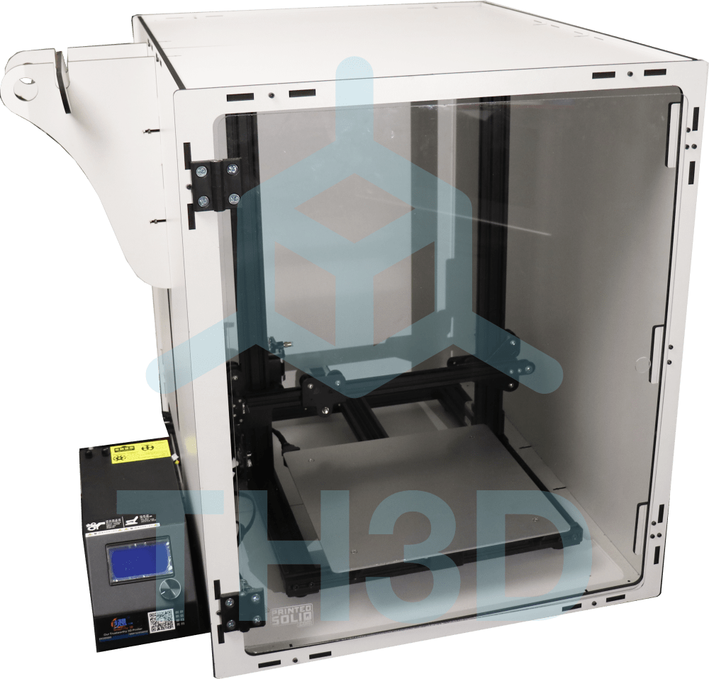
Acceleration of production processes
Speeding up processes drives business growth. When creating an electronic device, the design and ergonomics of the case are just as important as its performance. This requirement is easily implemented due to the ability to create complex forms very quickly. 3D printing is the fastest prototyping technology: unique prototypes can be produced without a mold, resulting in low part cost.
With 3D printing, the price does not depend on the number of parts, but on the amount of material used. By making multiple iterations of the same case, 3D printing will be a much more sustainable and sustainable manufacturing method than traditional ones. Using a 3D printed prototype, you can check the ergonomics, material features, as well as the fit of internal components or additional elements. With a wide range of 3D printing materials, you can evaluate their benefits and build quality based on project requirements.
3D printing is ideal for making plastic cases.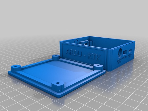 Whether you need to customize a product or follow Just-In-Time principles, the benefits of this technology for your business are undeniable.
iQB Technologies Experts Recommend Article: From Aircraft Prototype to Biomedicine: Sharebot Unleashes New Opportunities
Development of customized electronics enclosures
Which 3D printing material to choose?
What is the best material for case making? To develop a project and start 3D modeling, you must select the material and take into account the design parameters.
Plastic enclosures for electronics can be developed through additive manufacturing using adapted materials. Nylon-based materials such as Nylon PA12 or Nylon PA11 are especially suitable for 3D printing plastic cases. These are low-cost materials that can be used to make prototypes, as well as small or large series. Photopolymers with a variety of mechanical properties are also suitable for printing prototypes and finished products.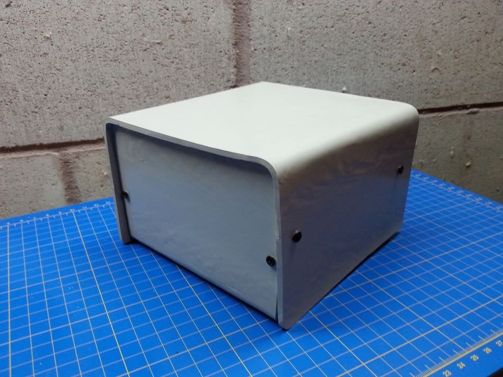
How to design enclosures for 3D printing
Before you start modeling a case, it is recommended that you start designing with the components that it will contain. This way you can place components and make sure everything fits, as well as provide clearance for connectors or cables. To ensure that all components will fit, we recommend leaving a gap of 0.5mm between the components and the 3D printed elements.
Access to components
The first thing to think about when designing a case is what to put in it and how to access it later. If access to the components is not required, you can design special fasteners or use adhesive during assembly of the case to completely seal it.
If access to the components of the case is necessary, the following mechanisms can be used:
-
semi-rigid eyelets;
-
sliding panels;
-
screws;
-
conventional and flexible hinges;
-
prefabricated structures.
Eyelets, slots and flanges help with assembly and alignment of parts. In addition, if the minimum dimensions of these elements are observed, they can increase the strength of the hull.
Durability of 3D printed case
The main thing to consider is the thickness of the walls of the case. This parameter determines the weight, stiffness, strength and possible applications of the hull. Even if the 3D printer is capable of printing small parts and thin walls, we recommend keeping the minimum wall thickness of 2mm. This value provides structural strength while keeping the weight of the part light. The optimum thickness can also be determined using the design guide for the material used.
However, be careful, because depending on the length of the casing, the 2 mm thick walls can bend, which can lead to some shrinkage.
Corner rounding is a key feature of 3D printing because hard corners can be printed poorly. Roundings are necessary both inside the case and outside.
Roundings avoid sharp corners and reduce stress
For external corners, a slight rounding (1 or 2 mm) can be used on the housing surface.
Inside the case, the corners can be reinforced with thickenings and roundings. A very small radius simplifies 3D printing and reduces stress concentration at corners.
Thickening and rounding inside the body reduce stress around the hole
3D printed housing: quality and precision
If the design contains gaps or holes for fasteners, select a material that provides the desired accuracy. 3D printing plastic provides high precision, but we recommend drilling or punching holes after printing with special tools.
If you slightly increase the diameter of the holes for the fasteners, the result will be better.
At the same time, for a tighter connection of the fasteners with the body, the diameter of the holes should be reduced.
Small walls and thin-walled elements are often added to the housing to hold components. These elements must meet the minimum thickness of the material used, and in addition, we recommend adding structures such as corners or stiffeners, which will make the element more durable and ensure correct 3D printing.
Corners and stiffeners reduce stress and make thin-walled elements and the case itself stronger
Finally, remember that in addition to rapid iteration and prototyping, 3D printing can be used to mass-produce cases.
The article uses materials from Sculpteo
Article published on 03/25/2021, updated on 06/15/2022
3D printed plastic cases
Direct 3D printing of electronic component cases allows manufacturers to quickly and cheaply produce the desired parts with a wide range of customization options. The resulting products can be used both as finished products and as prototypes for testing or mold making.
It will be profitable to use a 3D printer for printing cases if you:
- produce products, each copy of which (or a series of copies) is different;
- are engaged in the assembly of complex products according to customer requirements, which requires customization of the "stuffing";
- are engaged in the development of piece products;
- put the speed of production in the first place and it is important for you to have a 3D printer in your own office, and not wait 2-3 weeks for the contractor to produce the desired part.
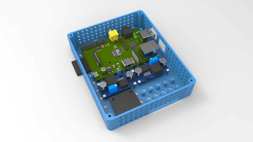
Usually, plastic is used for 3D printing of finished housings and structural elements of devices. In addition, individual high-precision samples (for example, to check the assembly, use as a master model) are made from photopolymer materials.
Benefits of 3D printing instrument housings and components
- Speed up development: it takes 6-7 hours to print a 20x20x15 cm plastic housing
- 70-90% cheaper than traditional methods
- Any geometry, complex composite structures
- High strength and build accuracy
- Easy to test products and make changes
- 3D printed parts can be used with traditionally produced parts
- Printed parts can be used both as finished products and as test prototypes or casting samples
It will be profitable to use a 3D printer for printing cases if you:
- produce products, each copy of which (or a series of copies) is different;
- are engaged in the assembly of complex products according to customer requirements, which requires customization of the "stuffing";
- are engaged in the development of piece products;
- put the speed of production in the first place and it is important for you to have a 3D printer in your own office, and not wait 2-3 weeks for the contractor to produce the desired part.

Learn more


