3D print bolt
Bolt best 3D printing files・Cults
Skip to contentM4 x 3mm Hex Nut (M4 Nut)
Free
M4 x 6mm Screw
Free
Pack Guy Armoured car + Humber armoured car
€10
Humber armoured car MkII MkIII MkIV 1/56(28mm)
€9
Guy armoured car/Humber amoured car MkI 1/56(28mm)
€8
Pack Panzer 1 Ausf A/Leicht Funk/Munitionsschlepper 1/56(28mm)
€10
Panzer 1 Ausf A 1/56(28mm)
€8
YAGE Geared Bowden Extruder M8 bolt 608 Wall mount
Free
crossbow bolt holder
€0.58
Rolly Toys Bolzen für rollyMega Trailer
Free
Adjustable bolt handle
€1
BOLT REVOLVERS PACK
€10
S.
€9.31
Screws and nuts
€1.27
RIVET WARS - CUSTOM - SPACE MARINE LANDRAIDER - JUST A LITTLE TANK
€3.90
New Custom 1/18 Ultramarines Apothecary 30K
Free
Black Bolt Illuminati - multiverse of madness low poly
€1.42
M16x30mm Nut and Bolt
Free
RIVET WARS - CUSTOM - SPACE MARINE DREADNOUGHT - JUST A LITTLE GUY IN A DREADNOUGHT
€3.90
Toilet Seat Bolt Screw
€3
AMD 165/175 Panhard 1/56(28MM)
€6.50
RIVET WARS - CUSTOM - Space Marine - Just a little assault guy
€2.79
Assault Cannon Upgrade for Heavy Rivet Guns
Free
RIVET WARS - CUSTOM - Space Marine Thunder Cannon- Just a little guy and his cannon
€3.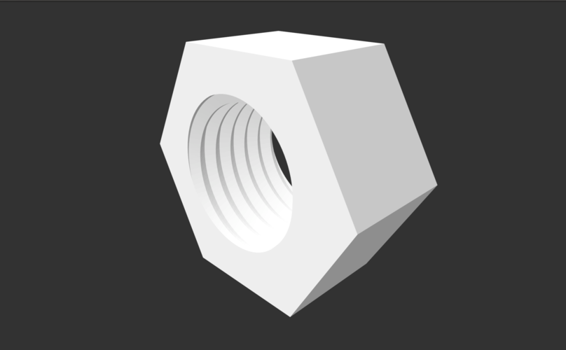 34
34
M4A4 Sherman/Sherman V/Sherman Firefly 1/56(28mm)
€11
RIVET WARS - CUSTOM - Space Marine - Just a little guy
€2.79
Sherman 105mm 1/56(28mm)
€10
Tactical Repeating Bow (TRB)
€10
Humber Scout Car 1/56(28mm)
€6.50
GrimGuard SF-19A Fighter Plane
€15.19
M16 screw bolt and nut
Free
Wahoo Bolt (v1/v2) Mount for Velomobile
Free
lock
€2.50
Wooden watchtower with guardhouse (11) - Alkemy Lord of the Rings War of the Rose Warcrow Saga
€1.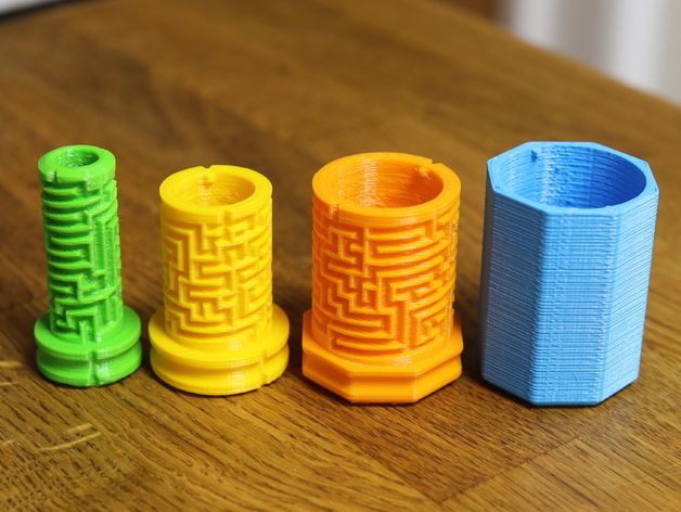 90
90
Scandinavian wooden house with large fireplace (10) - Alkemy Lord of the Rings War of the Rose Warcrow Saga
€1.90
Scandinavian house with large canopy and ornaments (9) - Alkemy Lord of the Rings War of the Rose Warcrow Saga
€1.90
Viking building with large thatched roof and roof window (8) - Alkemy Lord of the Rings War of the Rose Warcrow Saga
€1.90
Viking building in thatch and wood with ornaments (7) - Alkemy Lord of the Rings War of the Rose Warcrow Saga
€1.90
Viking building with bevelled roof and wooden column (6) - Alkemy Lord of the Rings War of the Rose Warcrow Saga
€1.90
Large Viking building with double entrance and railings (5) - Alkemy Lord of the Rings War of the Rose Warcrow Saga
€2. 90
90
Viking building with sloping roof (4) - Alkemy Lord of the Rings War of the Rose Warcrow Saga
€1.90
Large Viking building with floor and large door (3) - Alkemy Lord of the Rings War of the Rose Warcrow Saga
€2.90
Viking house with wooden door and roof decorated with horns (2) - Alkemy Lord of the Rings War of the Rose Warcrow Saga
€1.90
Viking house with high roof and big chimney (1) - Alkemy Lord of the Rings War of the Rose Warcrow Saga
€1.90
Scandinavian outdoor and camping accessories (set of 6 items) - Alkemy Lord of the Rings War of the Rose Warcrow Saga
€1.50
Gothic Scifi bullets and casings scaled to fit assault bolter
Free
Gothic scifi bullet set scaled to match bolt rifle
Free
Shell casings for bases
Free
3D Printing Threads and Adding Threaded Inserts to 3D Printed Parts (With Video)
There are many ways to attach screws to 3D printed parts, including inserts, tapping, and even 3D printed screw threads.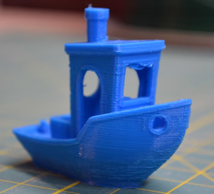
Screws are among the most popular fasteners in any material. Can you use off-the-shelf screws with your 3D printed parts? The answer is a clear yes, for both stereolithography (SLA) and selective laser sintering (SLS) parts.
In this article, we explore different methods of using metal screws with 3D printed parts, and provide some tips for incorporating screw threads directly into your 3D design.
Watch our application video about 3D printing threads and threaded inserts for 3D printed plastics.
Video Guide
Having trouble finding the best 3D printing technology for your needs? In this video guide, we compare FDM, SLA, and SLS technologies across popular buying considerations.
Watch the Videos
Let’s take a look at the various design options for 3D printed threads, which we’ve collected over the years within Formlabs and based on feedback from our customers. Our test part is designed to showcase all these methods at once:
We’ve grouped these options based on the type of fastening, with pros and cons of each option listed for different use cases.
Sample part
See and feel Formlabs quality firsthand. We’ll ship a free sample part printed on an SLA or SLS 3D printer to your office.
Request a Free Sample Part
In this section, we look at three ways to incorporate inserts and nuts into your completed 3D prints for strong, long-lasting fastening that stands up to multiple cycles of assembly and disassembly.
Pros
-
Very good hold into 3D printed parts
-
Metal threads are strong and wear-resistant
-
Installs with a simple press fit
Screw-to-expand inserts are cylindrical, with a slight taper and knurling on the exterior surfaces. During the design stage, incorporate a boss with a depth and diameter based on the insert’s specs into your part. Print and post-process the part as normal, following the usual steps for SLA or SLS post-processing, taking care to make sure no extra material remains inside the cavity, and install the insert with a simple press fit.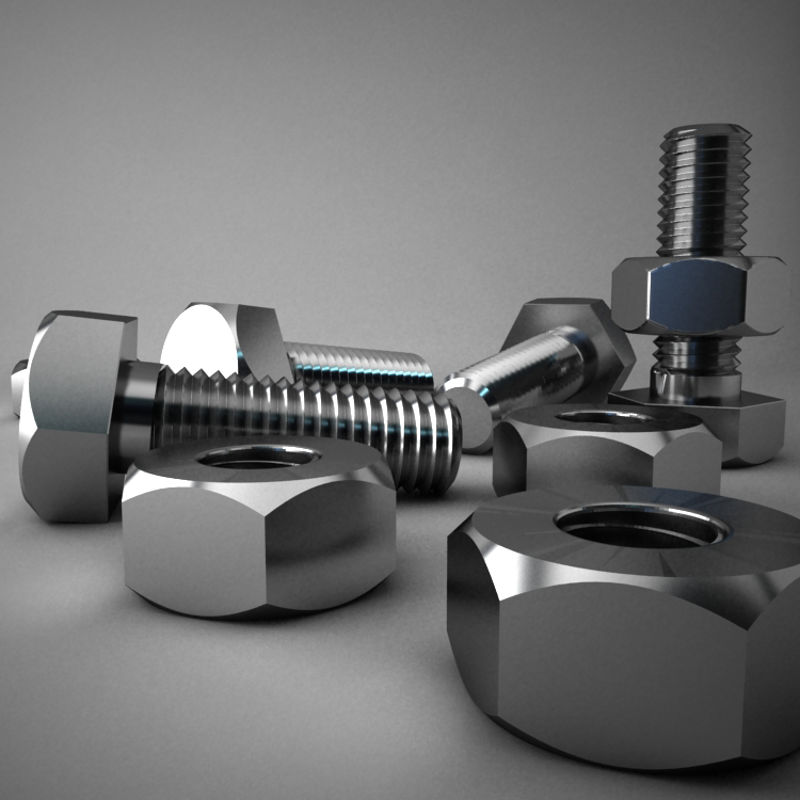 Adding a screw will press the knurled surface into the surrounding printed material, creating a strong friction fit.
Tip for using screw-to-expand inserts with 3D printed parts made with SLA 3D printing: Wash the part as normal, insert the screw-to-expand insert, install a screw, and post-cure the part with the screw in place. Saving this step for last reduces the chance that the insert will crack the surrounding material when expanded.
Heat-set threaded inserts are designed to be installed into thermoplastics using a soldering iron with an installation tip. They can also be used as glue-in inserts in thermoset materials, such as SLA parts.
To install in a thermoplastic part, like one printed with SLS Powders, follow the installation instructions for your particular hardware. The typical process is to use a soldering iron, with or without a special attachment, to heat the insert, which conducts heat into the surrounding plastic. The surrounding material softens and, by pressing down with the soldering iron, you can gently press the insert into the printed part.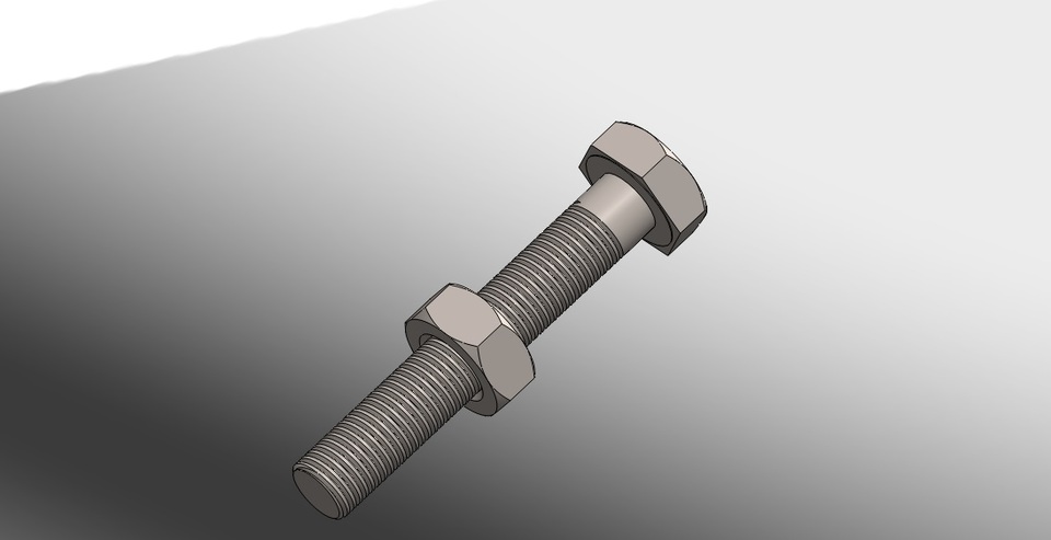 Be sure to allow enough time for the material to cool down and regain strength before installing a screw.
To install in a thermoset part, like one printed with SLA Resins, glue can be used to hold a heat-set insert in place. Unlike with traditional installation, make sure to design your boss to match the widest diameter of the insert, and use a bead of cyanoacrylate (CA) glue or epoxy to hold it in place when installed. Be sure to allow enough time for your glue to fully cure before installing a screw.
Note: In the SLS 3D printed part photographed for this article, the boss is sized for a press-fit, as we recommend here for thermoset plastics. This also works, with a drop of glue or epoxy, for thermoplastic parts, but won’t have as strong a hold as a true heat-set installation.
Although an additional step of soldering or gluing is required, heat-set threaded inserts for both SLS and SLA parts offer improved security and strength compared to screw-to-expand inserts With either method, these are a great option to gain a little extra security and strength compared to screw-to-expand inserts, although the additional step and equipment may be inconvenient.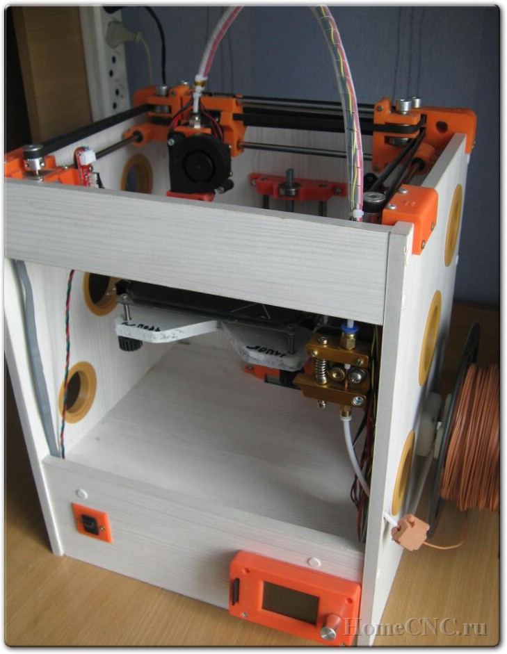
Cons
-
Pocket or boss needs to be designed into the part, and accessible after printing
-
Depending on geometry, may require glue and curing time
Designing a pocket or boss that securely holds a nut into the part itself is another method to get metal-on-metal contact. Hexagonal or square nuts can be used, and even locking nuts are possible to accommodate. There are many design variations for this method—just make sure your pocket or boss is easily accessible (i.e. not on an interior surface) so that the nut can be installed. For extra security, a drop of cyanoacrylate (CA) glue will hold the nut in place.
White Paper
Stereolithography (SLA) 3D printers such as the Formlabs Form 3+ have high accuracy and precision, and offer a wide range of engineering materials. Download our white paper for specific recommended design tolerances.
Download the White Paper
For speed and simplicity, it might be preferable to forego inserts and nuts in favor of screwing directly into a 3D printed part.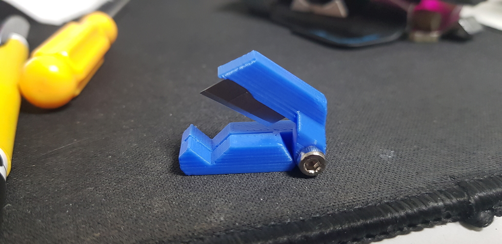 Whether tapping threads or using a self-tapping screw, off-the-shelf hardware designed for use with plastics work well with 3D printed materials like resins and thermoplastic powders.
Using a thread tap designed for plastic is a quick, economical way to add screw threads to 3D printed parts. It doesn’t require any extra design steps, and most shops that work with plastics will already have the equipment required.
Self-tapping screws, also called thread-forming screws, can be inserted into a negative feature with no preparation work done to the part. Follow the manufacturer’s guidelines for boss dimensions.
It’s suggested to use these with materials that are ductile, or have high elongation. Formlabs Nylon 11 Powder or Nylon 12 Powder are both suitable for this, as are the Tough and Durable Resins in the Formlabs SLA material family. Brittle materials, or those with low elongation (such as the Rigid Resins in the Formlabs SLA material family), may crack when used with self-tapping screws, so take caution and wear eye protection when using these materials.
Including threaded geometries in your printed part can be effective if you follow certain guidelines. Stick to larger thread sizes, at least ¼”–20 (imperial) or M6 (metric) or larger; reduce stress concentrations with fillets; and use thread profiles that are designed for plastics. For smaller screws, the threads should be customized to create a better fastener. For example, printing a semi-circular thread profile (on screw and nut) and using a 0.1 mm offset gives better thread engagement with improved wear characteristics.
SLA and SLS 3D printing are generally preferable for this method over FDM, because they are more precise and can create parts with a smoother surface finish. Any material with particularly low surface friction, such as Durable Resin, is less likely to show wear over multiple cycles of assembly and disassembly.
When preparing your part for printing, it's important to minimize support structures on any threaded surfaces to ensure your parts will come together smoothly without additional post-processing.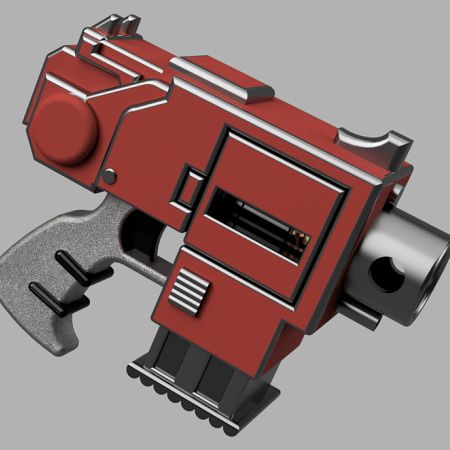
There are many options for combining multiple 3D printed components using screws and threaded fasteners. From directly 3D printing threads to using off the shelf inserts, you can choose any of the methods outlined above, based on the chosen material, the number of cycles of assembly and disassembly you anticipate, the strength required, and the amount of extra steps your workflow can accommodate.
Curious to see what 3D printing material might be right for your application? Use our interactive wizard to choose the best 3D printing material or request a free 3D printed sample part to see the quality firsthand.
Explore 3D Printing MaterialsRequest a Free Sample Part
3D printing - threads and screws
First things first: what is the difference between a screw and a thread?
A screw is a fastener used to form a connection that can later be dismantled, while the thread is the main fastener of the screw. In this case, the thread is not only used for screws; they are also present on pipes, in linear drives, worm gears and many other devices.
All threads have in common the way they are formed. Each thread is a continuous spiral groove of a certain cross section, made on the outer or inner side of the cylindrical surface.
In most cases, the cross section or shape is triangular or trapezoidal. Triangular thread forms are primarily used for fasteners (screws), while trapezoidal thread forms, varieties of square threads, are used for power transmission and linear drives on lead screws. To keep things simple, this article only covers triangular shaped threads, but everything applies to both types.
A further level of categorization distinguishes metric threads from inch threads. The former are mainly used in Europe and Asia, while the latter are used in America and the UK. To the untrained eye, they look the same, but the difference exists in the shape of the triangle and the pitch of the spiral curve.
In this article, we will cover the basics of designing and 3D printing screws and threads.
Basic Terms
There are a few terms and concepts that you should be familiar with before you start designing a thread.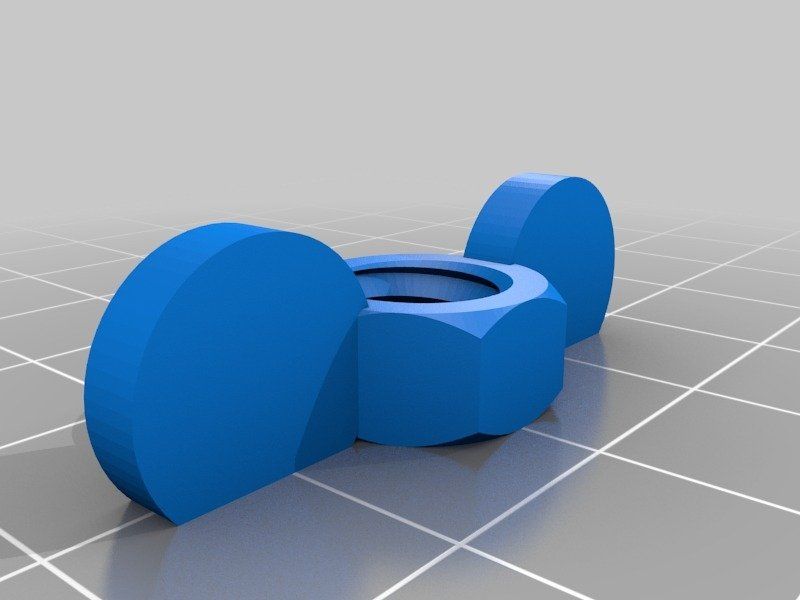
External or internal thread : external or external thread exits the cylindrical surface. The female thread is cut on the inner cylindrical surface. For example, bolts have external threads, while nuts have internal threads.
Thread axis : line through the center of the cylinder on which the thread is to be formed.
Base : the lower part of the groove that runs around the body of the thread.
Comb : The highest point of the thread profile.
Large diameter : The diameter of a cylinder enclosing the top of an external thread or the base of an internal thread. This cylinder is concentric with the axis of the thread.
Minor Diameter : The diameter of a cylinder enclosing the root of a thread on an external thread or the crest of an internal thread. This cylinder is concentric to the thread axis and large diameter. The smaller diameter is also known as the drill diameter when handling internal threads.
Pitch : distance between equivalent points on adjacent threads. For example, the distance between two adjacent crests of a triangular thread.
Metric thread: The "M" designation of a metric thread indicates the nominal outside diameter of the thread in millimeters. For example, an M5 thread has a nominal outer diameter of 5 mm. For external threads, the nominal outside diameter is equivalent to the major diameter. For internal threads, the nominal outside diameter can be determined by measuring the minor diameter and referring to the metric thread table.
Inch threads: Inch threads are designated using a number of standards, including the Unified Thread Standard (UTS), which basically refers to standard thread sizes as numbers (eg #4). The two most important measurements in UTS are the major or minor diameter of external or internal threads, respectively, and threads per inch (TPI).
Thread Modeling
Let's look at the process of designing external and internal threads using Fusion 360, which provides a simplified threading feature.
Other CAD programs have tools with varying degrees of similarity. It is important to understand the basics presented in the previous section. With this knowledge, you will be able to use any available modeling tool for 3D modeling.
Let's start with the outer thread of the bolt.
External thread
- Draw a circle with a diameter equal to the largest diameter of the desired thread.
- Create a cylinder by extruding a circle to the desired thread length.
- Go to "Create" and select the "Thread" option.
- Select the newly created cylinder. Make sure "Modeled" is checked. Set the thread type and other thread options. Click OK.
That's it. You have an external thread! To make a good bolt out of it, you need to attach it to the head to your liking.
Now let's create a nut with an internal thread.
Internal thread
- Create a hexagon. For the purposes of this tutorial, just make sure it's larger than the carving you want to create.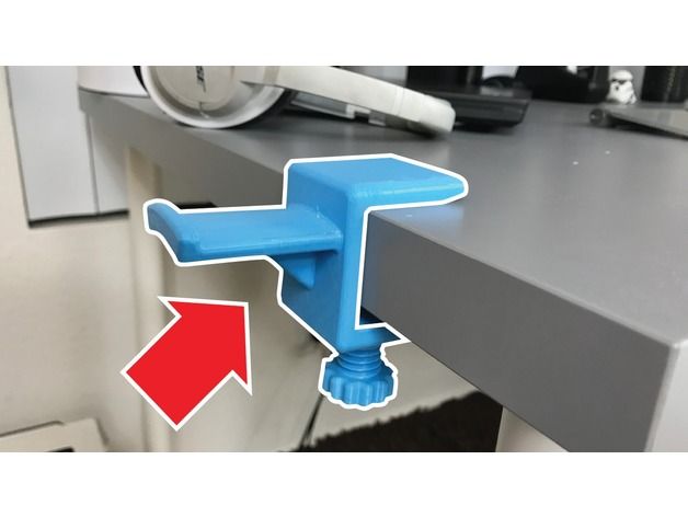
- Push it out to the desired height.
- Make a hole in the center by selecting the "Hole" option from the "Create" menu. The hole diameter must match the largest thread diameter.
- Select the inner surface of the newly created hole, go to "Create" and select the "Thread" option.
- Don't forget to check the "Modeled" option. Set the thread size and other parameters. Click OK.
That's it. Your first carvings are ready for 3D printing!
Tips for 3D Printing Threaded Parts
This may seem like a simple task at first glance, but printing threads is not always easy, especially if you need small diameters.
Assume you are using a 0.4 mm nozzle and a 0.2 mm layer height. With this setting, the smallest pitch you can achieve during 3D printing is likely to be around 0.5mm (give or take 0.1mm). This pitch is suitable for M3 threads and you should have no problem trying to print an internal thread on a relatively large part. This is because your threads will have enough time to cool while the nozzle is in a different location.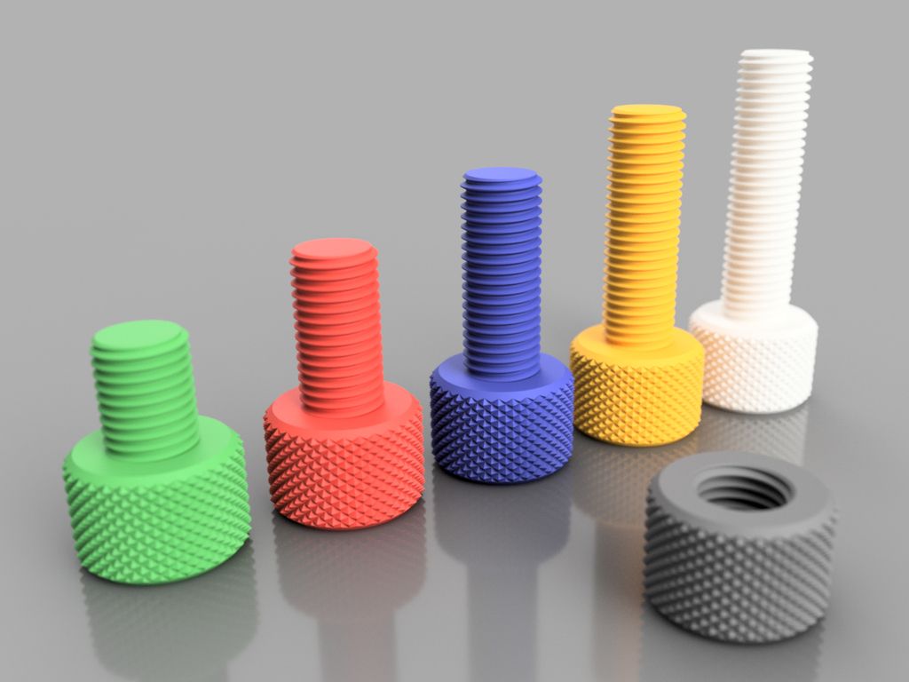
Things get interesting if you need an external thread, for example on a screw or bolt. In this case, the nozzle has nowhere else to go, which means that you will probably need additional cooling. Check your 3D printer before you decide to print a lot of thin external threads.
One of the most practical options before starting thread printing is the M10 3D Printed Thread Test. Thanks to this special 3D model, you will be able to check exactly what your 3D printer is capable of.
Settings when 3D printing parts with threads
Below are some general guidelines for setting up your 3D printer when printing threads.
- Make sure your 3D printer is properly calibrated. Extruder calibration is also important.
- Always try to print threads vertically. For best results, the thread axes should be perpendicular to your 3D printer table.
- Print without the calipers, or at least make sure they don't go inside the threads. Otherwise, removing them and maintaining functionality can be a real problem, especially with internal threads.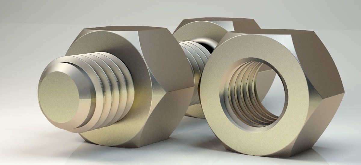
- If possible, use at least 4 vertical layers or vertical walls at least 2 mm thick. This will ensure the strength of the thread.
- Try to set the filling density to at least 25%.
- Layer height is an important parameter when 3D printing threads. For smooth operation, the layers should be as thin as possible. As a guideline, threads larger than M12 or 1/2" can be successfully printed at 0.2mm, while smaller threads should be printed at thinner layers.
Resume
Even if your first test fails, don't despair! Here are some final tips for 3D printing threads:
- Even if you manage to print beautiful external threads smaller than M6 (6mm in diameter), think twice before using it for heavy duty use. Due to the small diameter and the nature of 3D printing, this thread size is best suited for visual models only. If it must be a functional piece, consider a different design.
- Internal threads less than 4 mm in diameter have a small pitch, which makes 3D printing difficult. Consider printing a blank hole and tapping with a wrench that size. In any case, it's always a good idea to clean threads before use, whether it's 3D printing or trimming.
- Some materials shrink more than others. Before 3D printing large threaded parts, make some small samples to check the thread dimensions.
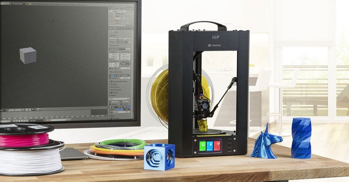
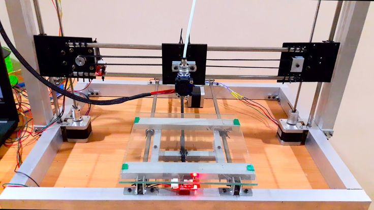
Your first 3D print with the Flying Bear Ghost 5 / Ampere
Let's assume that you've already completed the printer assembly quest and you can't wait to print something. Here's how to get started printing on the Flying Bear Ghost 5 and what settings to look out for in order to get the most out of your 3D printer.
Before printing on a 3D printer, the model must be prepared and divided into layers. Typically, 3D models are distributed in STL format - this is a kind of JPEG in the world of modeling. A three-dimensional object in the STL format consists of a set of polygons - triangles, the coordinates of which are described in the file.
However, printers are unable to process STL files themselves.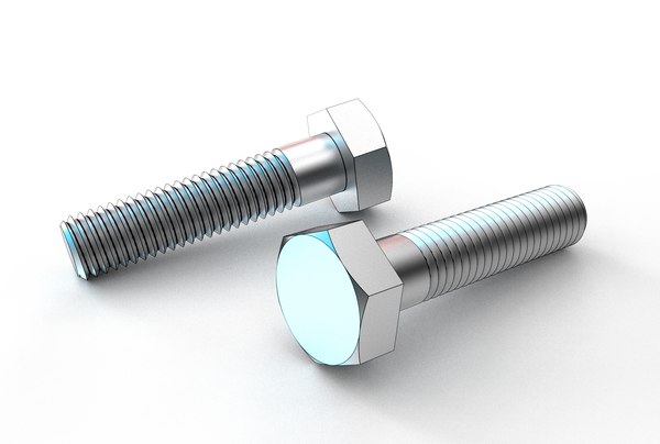 First, the selected model must be converted into a G-code - special commands for the printer that tell you where to move the head and at what speed to extrude plastic during the printing process. To convert an arbitrary 3D model into a G-code, there are special programs - slicers.
We will show how this operation looks like using the Flying Bear Ghost 5 3D printer as an example. We will process the popular 3DBenchy boat model in the Cura slicer.
This model is specially made to detect printing imperfections on 3D printers and calibrate settings. You can download any 3D model in STL format from specialized sites.
Slicer download
Any slicer program is suitable for converting models to G-code. In this example, we will use the Cura slicer - the most functional of the free programs. Download the slicer from the official site and run the installation.
Skip the welcome screens and accept the terms of use.
Setting up a printer in the slicer
Add a printer to the program using the "Add a non-networked printer" button.
Select "Flying Bear Ghost 4S" from the list. This is the previous model that has similar specifications to the Flying Bear Ghost 5.
Any printer name can be entered in the "Printer name" field. It is needed to distinguish between several printers or several settings profiles of one printer. Name it "Flying Bear Ghost 5".
Change the Z print area to 200mm. The "Z (Height)" field is responsible for this. The Gantry Height field will change automatically. Leave the rest of the fields unchanged. Click the "Next" button.
Changing the program language
For convenience, let's change the program language right away. Go to the settings using the "Preferences" → "Configure Cura..." button
Select Russian in the "Language" drop-down menu.
The interface language will change only after the program is restarted. Close Cura and reopen - you will be greeted by Russian-language menus.
Adding a model to the slicer
Click the button with the folder icon and select the downloaded 3D model file.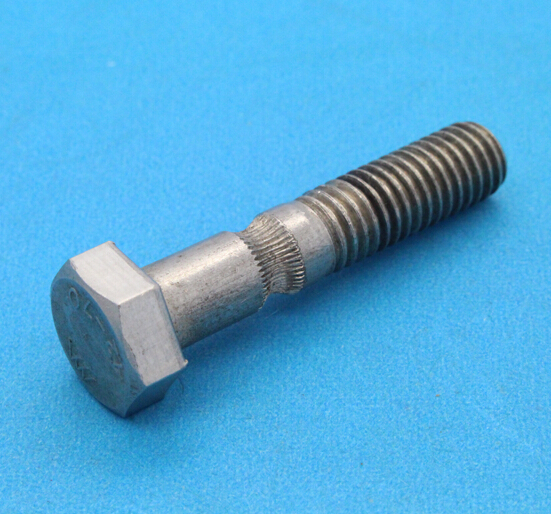
Print settings
All program management is placed in the top panel with three buttons.
Printer selection
The name of your printer is displayed in the upper left corner. We only added one model, so this item should be Flying Bear Ghost 5.
Plastic and nozzle selection on the printer
Your Flying Bear Ghost 5 printer allows you to print different types of plastics and use different diameter nozzles. Make sure that the standard 0.4 mm nozzle is selected in the program, which is installed in the printer from the factory.
Open the plastic and nozzle selection shutter. In the "Material" section, select your plastic. If you are printing with the test spool of plastic supplied with the printer, then select "PLA" in the "Universal" section.
Selecting slicing settings
By clicking on the long button on the right, a list with basic slicing settings is opened. The developers of CURA tried to make the program clearer, so they built hints into it. When you hover over an unknown parameter, a tooltip will appear that will help you understand what setting it is responsible for and what it affects.
Custom button opens detailed settings with many options. Leave all professional options at their defaults. We have enough basic settings.
The top slider "Profiles" is responsible for the height of one layer. The thicker each layer, the faster the model is printed. At the same time, by reducing the layer thickness, a more accurate print quality is achieved.
Set the layer height to 0.16 mm. This is the golden mean between speed and quality.
The second Infill slider controls the interior of the model. The printer can print only the walls of the model, and leave the internal volume empty. This will greatly reduce plastic consumption, but will negatively affect the strength of the model. So that the finished plastic part does not fall apart in the hands, its insides do not remain empty, but are filled with a mesh. The resulting edges increase the rigidity of the model.
To strike a balance between model strength and plastic consumption, set the infill to 20%.
Also in the slicing settings menu are two additional options: supports and sticking.
If the part has protrusions that hang over the table, then the printer will not be able to print them - they will simply fall. To prevent this from happening, activate the "Supports" option with a checkmark. Under the overhanging parts, columns will be printed that will support the part.
There are no such parts in our test model of the ship, so the "Support" parameter does not need to be activated. But if you print your own model - do not forget about the supports.
The Stick setting improves adhesion. This is the adhesive force between the workpiece and the table. If the adhesion is insufficient, the part may come off during the printing process. The printer will print a skirt around the model, which will increase the contact area with the table. After printing, it can be cut off, but it will not allow the model to come off the table in the middle of the process.
Activate this option, because the bottom of the boat is quite shallow, and an additional surface for stronger adhesion will be very useful.
Preview
Click the Slice into Layers button. After that, the slicer will calculate the trajectory of the head and generate a G-code.
Switch to the "Preview" tab, where you will see the built layers of the model. The preview helps you check your print settings and understand how your model will print.
G-code export
To record the finished file, it is easiest to connect a microSD memory card to the computer through the adapter supplied with the printer. The slicer will immediately detect the removable device and offer to save the file to it. Save the G-code to a memory card, or use the drop-down list to save to a file, and then manually copy to the card.
Table Calibration
The initial setup has already been done when the printer was assembled, but the table may fail over time. If the model does not adhere well or, conversely, the first layer is too thin and the extruder starts to click, then the table must be recalibrated using the four corner screws.
If the screws are unscrewed to the limit or, on the contrary, compress the springs to the maximum, adjust the Z-axis calibration screw. Go to the "Tool" tab.
Go to the "Leveling" tab.
Press button "1". The printer must place the nozzle in one of the corners
Place a sheet of paper between the nozzle and the table. Use the adjusting screw to adjust the table so that the sheet of paper is jammed. Repeat the calibration in each corner of the table.
Replacing the filament
Before the test print, we already loaded a test filament spool, but sooner or later you will have to change it. For example, if you want to print in a different color or try a different type of plastic. To do this, you first need to remove the remnants of the old plastic. We will change the plastic to another one, or remove the remnants of the old one.
The printer will not let you operate the extruder while the nozzle is colder than 190 degrees and will automatically raise the temperature before any operation. However, high temperature plastics can remain hard and the extruder will not be able to push or pull the filament. For them, it is necessary to additionally heat the nozzle above 190 degrees using the "Preheat" menu.
Go to the Filament menu.
The two large arrows on the screen can either push the bar down or pull it back out.
The speedometer button can be used to switch the plastic feeding speed.
"High" - high. It is best used when the plastic is fed through the Teflon tube, but has not yet reached the nozzle.
Low Set this speed to squeeze the plastic out of the nozzle. At high speed, the nozzle section is not enough.
In order to pull out the plastic thread, press the up arrow. Wait until the plastic thread is completely pulled out of the Teflon tube by the extruder.
The printer will warn you if the nozzle temperature is less than 190 degrees.
After the nozzle has reached operating temperature, press the "Confirm" button and the extruder will turn on.
After the end of the old filament comes out of the extruder, press the down arrow. The extruder will start pushing the filament towards the nozzle.
The end of the plastic thread on a new spool is usually threaded through the holes to keep it from unwinding. Trim it as the deformed end may get stuck in the filament sensor or extruder.
Remove the uneven end of the plastic with wire cutters.
Pass the bar through the filament sensor and then into the extruder.
Wait until the bar reaches the nozzle. As soon as plastic starts flowing from the nozzle, switch the speed to low so as not to ruin the extruder. Wait a little for the remnants of the old plastic to pour out of the nozzle. The color should change to a new one.
Then press "Stop" on the screen.
Printing from a memory card
Adhesion must be considered before printing. The glass has a special coating that improves the adhesion between the first layer of plastic and the table, but larger models may have curled edges. To improve adhesion, you can thinly anoint the table with a glue stick or sprinkle with hairspray.
Insert a memory card into the bottom of the printer.
Use the arrow in the upper left corner of the screen to exit to the main menu.
Go to the "Printing" section.
Select a file to print from the memory card.
Confirm the print by pressing Confirm.
After that you will see a progress bar with the print status and some buttons.
The printing process does not start immediately. Wait a few minutes for the printer to heat up the bed and nozzle to operating temperature.
The red button with the “Stop” sign is needed to urgently stop printing if something went wrong, and the green one with the “Pause” sign to pause it.
The screen has an indication of the table and nozzle temperature, cooling power, print speed and extrusion ratio. If you click on the icon, you can change the corresponding parameter directly during printing. All the parameters from the slicer are suitable for us, so we don’t need to change anything on the printer.
Wait for the table to cool down after printing. Parts are much more difficult to remove from a hot or warm table. Remove the piece with a spatula.
Wi-Fi printing
The Flying Bear Ghost 5 printer supports Wi-Fi printing. You can not throw off the file on the memory card, but immediately give the command to print from the slicer. To do this, the printer must be connected to your wireless network and add support for printing over Wi-Fi in the slicer.
Connecting the printer to a Wi-Fi network
Press the Tool button.
Go to the "WiFi" section
Select your wireless network from the list.
Enter the password for the Wi-Fi hotspot.
The printer has connected to the router. Make a note of the printer's IP address. You will need it when setting up the connection in the slicer.
Cura Wi-Fi connection
Press the Store button. A window with plugins for the slicer will open. Add-ons are needed to expand the standard features of the program.
In the add-on store, select "MKS WiFi Plugin" from the list.
Install the plugin.
Agree to the terms of use.
Click the Manage Printers button.
Click the "MKS WiFi" button to connect your printer via WiFi.