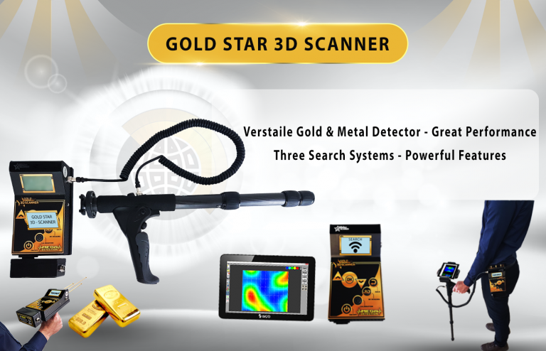
3D gold scanner
Gold Star 3D Scanner Device Works With 8 Search System Suitable For All Goals
Integrated Results Display & Feedback System
Gold Star 3D Scanner provides the user with the best integrated system to display the results resulting from the various search technologies included within the device.
This integrated system provides comprehensive and complete information for the prospector about the nature of buried targets and all their details.
The results display & feedback system combines an integration between sound, image and light to provide the best experience for the prospector. this is done through the following tools:
Colored LCD Screen
The main unit includes a high-definition color liquid crystal display (LCD) screen with a large size that secures a better view when adjusting the various settings such as selecting the search system and the ground scanning settings and provides reading numbers and charts representing the results clearly.
Gold Star 3D Scanner ‘s screen provides visual presentation of the results within the device’s program with useful information for the prospector, including the direction of search and a report on the type of metal, like in long-range systems, and a two-dimensional representation of the scanning area and its contents of possible targets in the imaging systems.
Android Tablet & Analysis App
Gold Star 3D Scanner comes bundled with a tablet computer running on an Android system and a pre-installed 3D analysis app to visually represent the results resulting from the scanning in the imaging systems in the form of a multi-color three-dimensional graphics, which gives the prospector the ability to analyze the data and know all the information about the detected targets such as depth and precise location , through the tools it provides with an easy and simple interface that enables the prospector to analyze the graphics to obtain detailed information about all the targets within the scan area.
Sound Feedback
Most of the search systems available in the Gold Star 3D Scanner device provide an audio output through audio tones via built-in speaker, the audio tones direct the user and give him an idea about the progress of the search process.
Example: In a live stream system, the device emits sounds related to the type of target metal, and the sound intensity varies according to the proximity and distance from the target.
Light Feedback
VST sensor, which is used in the PINPOINTER and LIVE STREAM search systems, contains LED lights that illuminate in a variable color according to the type of the target near the sensor (iron or metal, precious metal or space) and this provides the prospector with an idea about the type of target.
Easy to Use Multi-Language Program
Gold Star 3D Scanner software program is designed according to the latest design standards for modern user interfaces and user experience with a modern, attractive and practical design that combines clear texts, expressive icons, consistent colors, and animation.
The program provides an easy-to-use experience for beginners and professionals alike, as they enable them to set various search-related settings such as search systems, search programs, depth field and forward distance in long-range systems, ground scanning settings, and others.
Gold Star 3D Scanner program provides a visual display of the search results for most of the eight search systems and their various options in the form of graphics, charts and indicators accompanied by the various sounds that are associated with choosing a specific button or moving between settings and others.
One of the important features of Gold Star 3D Scanner program – to provide access to the largest segment of prospectors around the world – is its availability in 12 international languages that represent the most widespread languages in the world (English – French – Spanish – Arabic – Chinese …)
Powerful External Battery
Power is supplied to the device through a 12-volt lithium-ion rechargeable battery, designed with a special design in the form of an external box with an on / off button.
Gold Star 3D Scanner battery guarantees a long operation time, that is related to several factors, including the search system, the search tools used, and the power saving settings available in the device program.
Phoenix 3D Metal Detector | New Gold Detector 2023
New ground scan technology with new tools
Phoenix imaging ground scanner includes two probes used to conduct the survey and incorporates the first technology of its kind
Multi-Ground Scanner (M.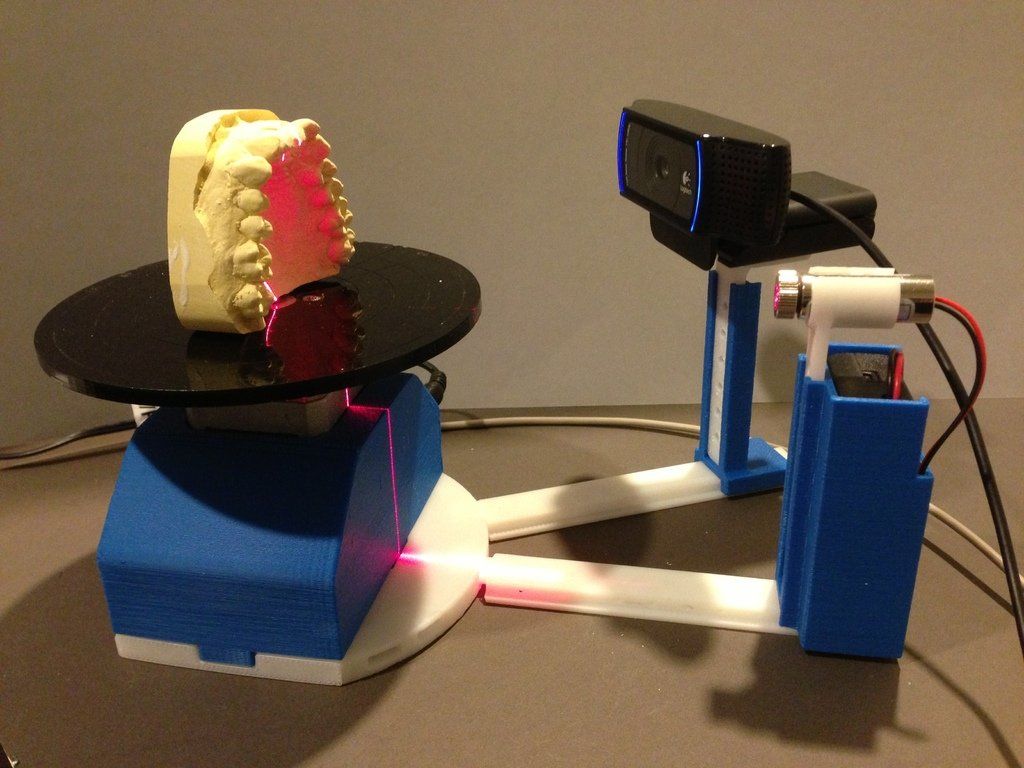 G.S)
G.S)
It is the probe that is used to conduct a three-dimensional imaging scan of the ground and with the advanced technology with multiple sensors built within it to better capture the signals of targets within the ground, with a relatively wide surface that ensures covering a wider area of the ground at each scanning point, thus ensuring the user a faster scanning process while ensuring accuracy in Results.
The captured ground scan data is transferred through the scanner via the scanner cable connected to the main unit of the Phoenix device to display the data graphically, or it is possible to transfer the data directly wirelessly to be represented in a three-dimensional graphical form on the tablet computer.
Vertical High Signal Transceiver (V.S.T)
This probe includes advanced technology in sending and receiving magnetic signals, as the probe captures the signals of magnetic fields resulting from various targets within the earth (non-precious iron metals – precious metals such as gold – voids, and caves …)
The VST probe features a unique design with a conical end in the form of a four-sided cone, which includes on two sides of the cone a group of rows of LED light buttons, and these LEDs change the color of their lighting according to the target that the probe passes over, which forms a pointer to the user indicating the nature Detected target.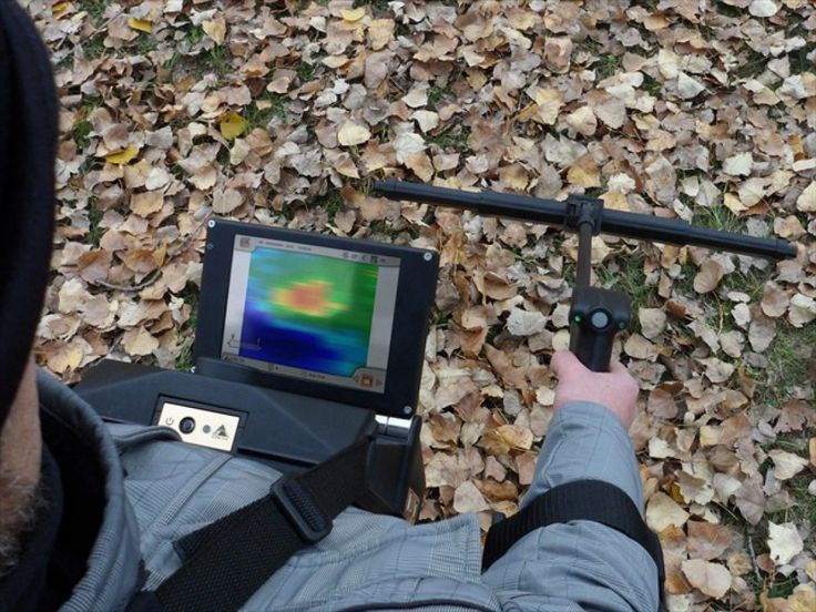
For example, the LEDs will light up in red color when the V.S.T probe passes over a metal target such as a gold coin. On the other hand, the color of the light buttons is blue in the event that it passes over a vacuum such as a tunnel.
The signals captured through the probe are converted into digital signals that are processed and displayed on the device screen or the tablet screen in the form of a colored outline that reflects the nature and type of potential target metal, as will be explained later.
3 search systems
Phoenix device includes all imaging scanning technologies in one device through three search systems that use the two previous probes. The search systems provide the user with the ability to use the device for multiple applications according to the purpose of the search.
The search systems in the Phoenix device include the following systems:
1 – 3D Ground Scan System [GROUND SCAN]
3D ground scan system is the most powerful system for detection in Phoenix device, it is developed with a new technology incorporated in the scanner probe called Multi-Ground Scanner or M.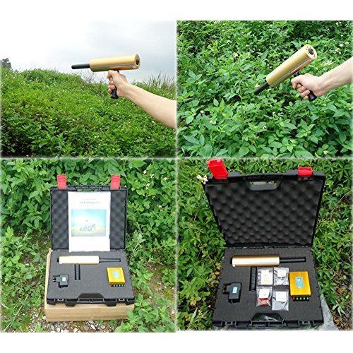 G.S in short.
M.G.S with its unique design and large surface with multiple sensors, enable coverage and scanning of larger area in less time but with more accurate results.
3D ground scan system displays the scanning data obtained from M.G.S as 2D visualization on the device screen or as 3D graphics presentation on bundled Android Tablet via Multi Visual Analyzer app as we will explain later.
After selecting the system from the main menu, the device program allowing the user to choose how to display the scan results. There are two options:
1 – Device
This option if selected enable the user to complete the 3D ground scan process using the device LCD screen as the results will display directly on the screen, before that the user must adjust the ground scan settings that include the following options:
- Mode
This option defines the method for conducting the ground scan, meaning how the measurements will be recorded at each scan point.
Here there are two modes:
- Manual: in manual mode, the recording of scan measurement performed manually by the user using the red button in the main unit of the device.

- Automatic: in this mode, the device is responsible for taking measuring points automatically
- Path
It expresses the shape of the user’s movement path when conducting a ground scan, there are two types:
- One Direction: In this case, the scan points are recorded in each scan line in one direction. In other words, the direction of measurements recording is in a specific direction in each scan line, for example, starting from the south towards the north, and so on for each line, meaning that the start points of the scan lines are on the same side.
- Zig Zag: here the direction of measurements recording in two consecutive scan lines are in opposite direction, meaning that the start points of two consecutive scan lines are on the opposite sides.
- Size
It is a dimension of a virtual scanning grid made up of cells, related to the number of scan lines and points in each scan line.
It includes the following two values:
- Width: it is the width or number of columns in the grid, it same as the scan line count.

- Height: it is the height or number of rows in the grid, it equal to the number of scan points
- Start Point
It is the starting point for a ground scan within the pre-defined area, and one of the following two options can be chosen:
- Left: in this case, the scan process starts from the bottom – left corner of the scan area
- Right: the ground scan will begin from bottom – right corner of the area
After setting the previously explained ground scan settings, the Scan tab displays a table summarizing the selected settings with a button to start scanning, and the user can press the OK button to actually start the scanning process and record the results.
During the scan process, the measurement in every scan point will be presented visually on screen as a 2D grid consisting of rows and columns of cells and every scan point presented as a cell with 4 sub-cells in specific colors based on the type of target that M. G.S hover in this point.
The table below shows the type of target for each color:
| Green | Light Blue | Blue | Yellow | Red |
| Normal Ground | Small Cavity | Cavity | metal objects | gold |
On the left side of the screen near the grid, there are many values presented:
– Current X: it presents the current scan line number or current column number in the grid.
– Current Y: it presents the current scan point or current row number in the grid.
– Value: a numeric value related to measurement in the current scan point.
2 – Tablet
If the user selected this option on the device screen, first he must make a wireless connection between the device and tablet, he must continue the 3D ground scan on the bundled Android tablet.
In this case, the user chooses the same ground scan settings as explained previously, but inside the Multi Visual Analyzer app, and the ground scan data visualized as 3D graphics inside the app.
Multi Visual Analyzer app can be installed on any Android tablet or smartphone, it has a simple graphical interface available in 12 languages, it used to adjust settings of ground scan and scan data transmitted in real-time from M.G.S to be presented as 3D graphics with different colors that refer to various target’s types such as metal, cavity or gold like in the previous table.
Multi Visual Analyzer app includes a set of tools to display the data from different viewports and tools to know the location and depth of specific target visually, and filters to filter results based on specific target types.
2 – Live Stream System [LIVE STREAM]Live Stream scan system is powerful ground scan mode with a live real-time scan of the ground and direct visualization of measurement on a display screen or optionally on the tablet via Multi Visual Analyzer.
The scanning process in this system carried out by a Vertical High Signal Transceiver (V.S.T) probe, a new probe with unique technology to perform a deep live scan to detect different types of targets including ferrous metal, non-ferrous metal, and cavities like tunnels or caves.
V.S.T installed in front of Phoenix main unit and must be vertical, it must always be perpendicular to the ground during the scanning process.
At the end of the probe, there is a four-sided cone with two sides containing a set of luminous LEDs, whose colors change during the scanning process according to the target type.
For example: When a user moves a V.S.T probe over a golden object like a golden coin the LEDs will light up in red color, it will light up in blue when V.S.T passes over a cavity.
After selecting the Live Stream system from the main menu, the screen displays a screen to calibrate the V.S.T probe first, then move directly to the live-stream screen that displays a continuous stream of colors changing during scan made by V.S.T based on target type in a similar way as explained for LEDs, on the right of the screen a numerical value of target displayed, the user here can change the speed of the stream.
For example, the color is Red when capturing a precious metal signal and green for normal ground.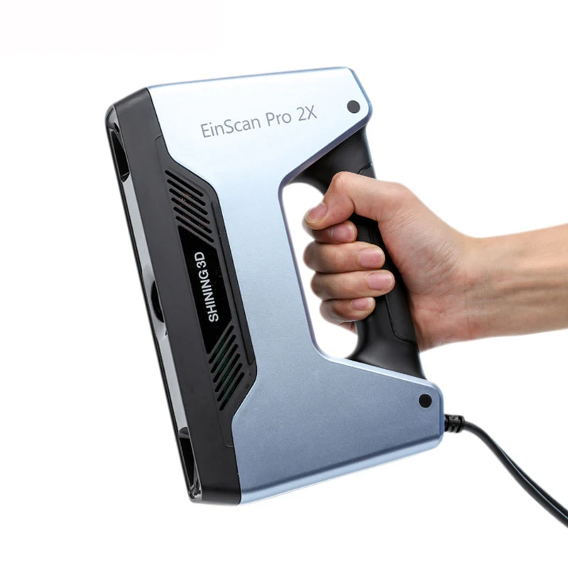
Users can also display live-stream visualization on tablets via Multi Visual Analyzer, in this case, they must connect the device and tablet via Bluetooth, and selecting Live Stream inside the app.
Multi Visual Analyzer app will display a changed-color stream of received scan data from V.S.T, here also the colors related to the target type in the same way.
3 – Pin Pointer System [PINPOINTER]The Pen Pointer system is a system usually used after excavation in order to accurately locate a potential target.
The scan process is carried out here via a V.S.T probe also, and in a similar way to the live stream system, where the probe must be perpendicular to the ground as well.
Pen Pointer used to determine the presence of a metal target or cavity with the precise determination of the location in which the buried metal or cavity is located via audio feedback or visualization on screen as 2D bar graph.
In the result screen there are many settings that user can adjust:
- Sensitivity
The sensitivity value is related to adjusting the sensitivity of the captured signal through the V. S.T probe, according to this value, the visual representation of the signals and the tone of the audio output changes.
- Calibration
User can use this option to calibrate the sensor sensitivity at any time according to the ground type and the ground state.
- Reset
This option reset the calibration process to its default value.
The visual representation of received signals on device screen is a 2D bar graph.
In case of signals of the metallic target such as bronze statue, for example, the bar graph will be consisting of bars facing upward, of different length, with graded colors from green to red in the middle at the maximum values, and then graded towards green on sides.
If received signals are for cavities – such as a tunnel – it will be made of bars facing downwards, of different length, ranging from green to dark blue in the middle at the maximum values, and then graded towards green at lower values.
A versatile integrated system for displaying results
The Phoenix imaging scanner provides the user with the best integrated system for displaying the results resulting from the scanning process through multiple scanning probes, providing the user with an integrated experience to know the scan results and accurate details of the detected targets.
The results display system includes the use of a two-dimensional visual representation on the screen and a three-dimensional representation on the tablet and with sound or visual alerts, as will be explained in the following paragraphs:
Large color display
The main unit of the device includes a high-definition color liquid crystal LCD screen with a relatively large size that provides a clear view for the user when adjusting the various settings such as selecting the search system and the ground scanning settings and provides reading numbers and charts representing the results clearly.
The device’s color screen provides visually displaying the results within the device’s program with useful information for the prospector through a two-dimensional graphic visual representation of the scanning area and the contents of the targets.
Multi Visual Analyzer application
The application, which can be downloaded on any tablet – tablet – or smartphone running on the Android system, enables the user to see the results of the survey in the two ground scanning systems in the form of a three-dimensional drawing and in the live broadcast system in the form of a variable color flow.
The Multi Visual Analyzer application is used to control the settings of the ground survey and displays the survey results within a multilingual graphical interface through which it can analyze the graphics and know all the information about the detected targets such as depth and exact location through the tools it provides enables the prospector to analyze the drawing to obtain detailed information about all the targets located within The area being surveyed.
The sound
The search systems in the device provide audio output through variable sound tones according to the target and signals in the case of the V.S.T probe, and in the case of scanning by the scanner, it provides audio alerts that indicate the user when recording measurements at the scan point or reaching the end of the scan line.
Light buttons
The V.S.T probe contains, as previously explained, a set of LED-type buttons that give the prospector during scanning by the probe a direct visual feed indicating the nature of the target.
Easy to use multi-language program
The device program is designed according to the latest design standards for user interfaces and user experience with a modern, attractive and practical design that combines clear texts, expressive icons, consistent colors, as well as animation.
The program provides an easy user experience for beginners and professionals alike, enabling them to set different settings for the ground scanning process, and it also provides a visual display of the survey results for the three search systems and their various options in the form of graphics, charts, and indicators accompanied by the various sounds that are associated with choosing a specific button or moving between the settings and others.
One of the important features of the device program to provide access to the largest segment of prospectors around the world is its availability in 12 international languages that represent the most widespread languages in the world (English – French – Spanish …).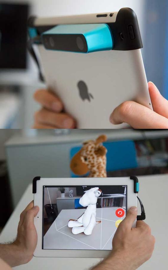
The device provides the ability to set many options such as the device’s program language, set the date and time, adjust the brightness and brightness of the screen, security options, lock the device with a password, and options to reset …
External battery
The power of the Phoenix device is provided by rechargeable lithium-ion batteries with a voltage of 12 volts and designed with a special design in the form of an external box with an on / off button with a battery status indicator.
The battery guarantees a relatively long use time, and the operating time is related to several factors, including the search system, the search tools used, and the energy-saving settings available in the device program.
3D scanning technologies in pursuit of Olympic gold
News
Subscribe to the author
Subscribe
Don't want
2
The Italian national cycling team used a 3D-scanner manufactured by the Russian company Carylib3D-scanner to improve the aerodynamics of the Russian company Carylib3D-scanner for the Tokyo Olympics.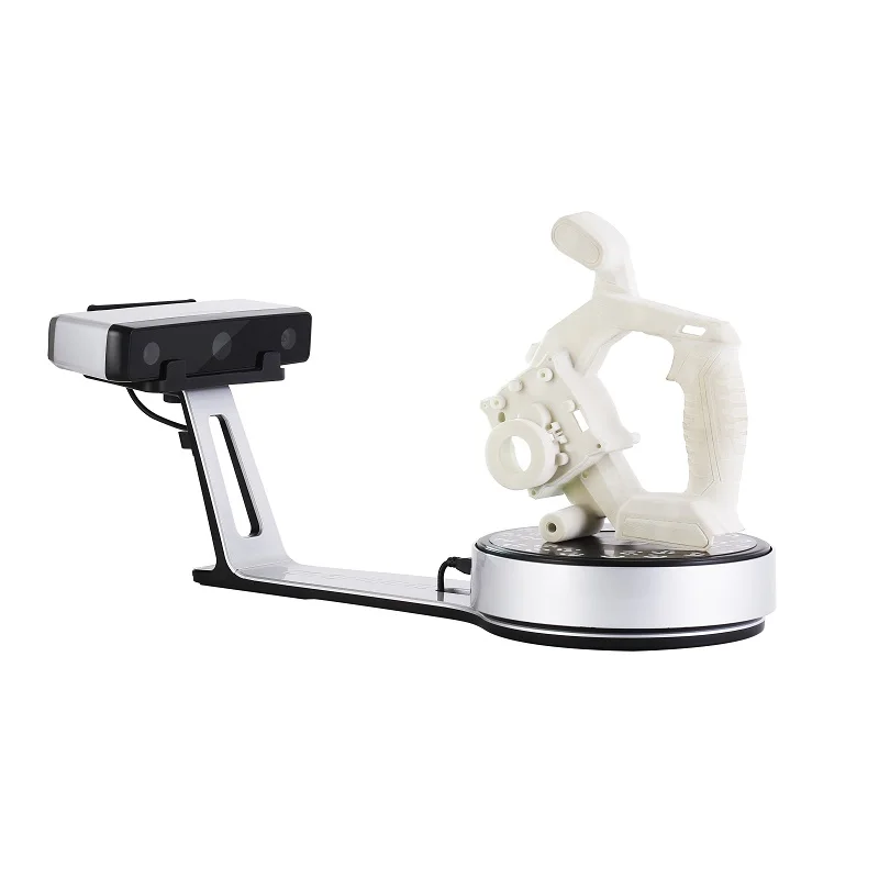 In just two minutes, 3DiTALY has made a series of high-resolution 3D models that will be examined by engineers.
“More than any other invention, the bicycle resembles an airplane: it minimizes contact with the ground, and only its modesty prevents it from flying” (Mauro Parrini, philosopher).
It is hard to underestimate the importance of aerodynamics and the impact it has on a rider's performance. In the world of cycling, speed is everything.
This project came to life thanks to Pinarello and Hardskin, two famous brands in the world of cycling, supplying the Italian national team with all the necessary equipment. Pinarello is the official bike supplier, while Hardskin makes sportswear. In light of the upcoming Tokyo Olympics, Pinarello and Hardskin decided to join forces to find a way to improve the aerodynamics of cyclists.
A few months ago, Hardskin asked 3DiTALY to digitize Pinarello athletes and bikes. The project was implemented in February 2021 at the Montichiari Velodrome in the province of Brescia. Funded by the municipality of Montichiari, it is the first and only indoor facility in Italy dedicated to track cycling.
The 3D scan of an athlete was the first step in a long technological chain needed to study aerodynamics. High accuracy and reliability of the device were required, so the Calibry 3D scanner was chosen.
Body scan included the following steps:
- Athlete warm-up and mechanical stand preparation.
- Race simulation to find the maximum aerodynamic position.
- Fixing the selected position. The athlete was wearing a bike uniform and a helmet to fully simulate the conditions of the race.
Thanks to the high performance of Calibry, the scan was completed within two minutes. The data was processed in the Calibry Nest software and transferred to Pinarello engineers for subsequent aerodynamic studies.
3D scanning is a fast and convenient way to collect data because the 3D model file contains all the information you need to analyze aerodynamics and design a custom steering wheel. After analyzing the data array, Pinarello will create a part (handle) in a single copy in order to achieve the maximum symbiosis of the rider with his bike.
Detailed information about 3D scanners of the Calibri family is available on the Thor3D official website.
Do you have interesting news? Share your developments with us, and we will tell the whole world about them! We are waiting for your ideas at [email protected].
3D scanner sport thor3d Calibry 3DiTALY
Follow author
Follow
Don't want
2
More interesting articles
ten
Subscribe to the author
Subscribe
Don't want
Serial production of Dobrynya quadrocopters has been established at the Obukhov plant in St.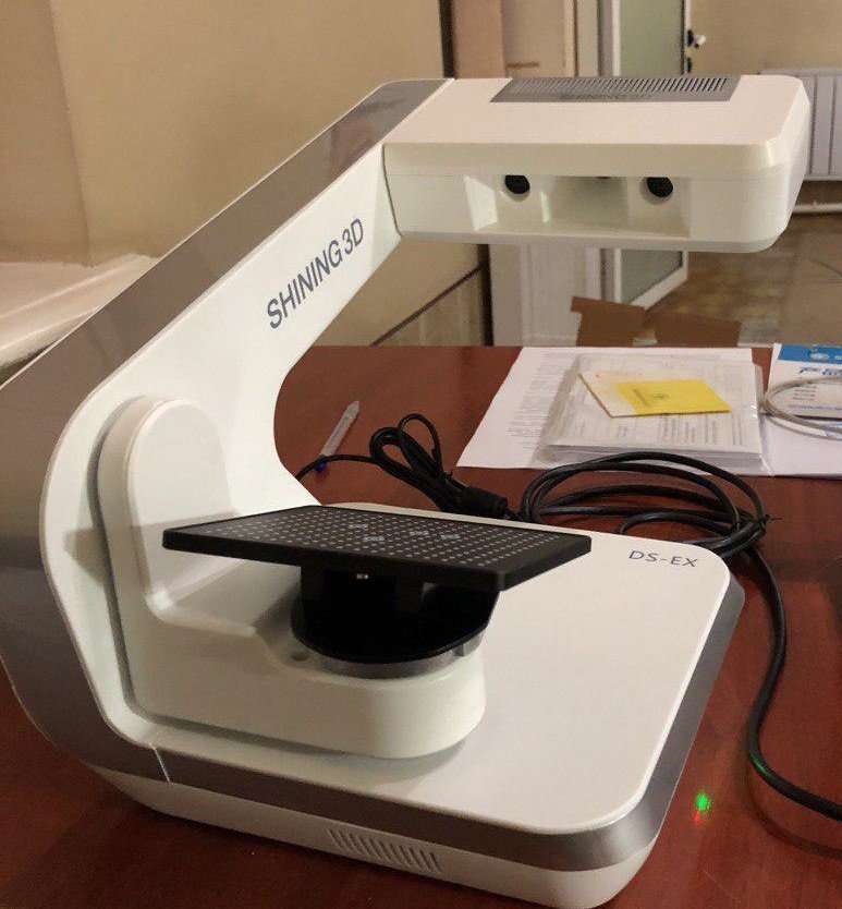 Petersburg. Cost...
Read more
5
Follow the author
Subscribe
Don't want
Compared to traditional casting, 3D printed sand casting has several advantages...
Read more
82
Subscribe to the author
Subscribe
Don't want
Collaboration 3D
We are pleased to present you our joint development with Speci...
Read more
Created the most accurate 3D scanner | Jewelry.INFO
07/05/2019 03:53 Production
Ukrainian inventor Leonid Nazarenko and his son Denis create a high-precision 3D scanner for jewelers. It has no analogues in the world in terms of price and quality.
The story of two inventors began about four years ago when they wanted to get high-precision 3D models of small objects, such as coins or figurines. But faced with the fact that the laser scanners available on the market, firstly, are very expensive, and secondly, their accuracy left much to be desired.
The very idea of the scanner was born when Denis Nazarenko was trying to make a model of the statue of Manjushri. “But scanners capable of capturing the smallest details of a model cost at least 17,000 euros and were out of reach for a small company. So we decided to create our own,” the Kickstarter presentation reads.
Who are Nazarenko
In a small office in the town of Vyshneve near Kyiv, father and son set about experimenting. The background allowed them to use deep knowledge from completely different engineering fields.
Leonid Nazarenko began his career at the Antonov plant, which built the world's largest An-225 aircraft. He created models of aircraft from childhood, and then taught schoolchildren to do the same. Leonid had a good understanding of metalworking and a wide range of knowledge in engineering disciplines.
Denis Nazarenko won various competitions in mathematics, physics and computer science. He has been working on software development for many years. And his most famous project is Start Menu X, a convenient alternative to the Windows Start menu, which has been used by many people around the world.
LED vs. Laser
Two engineers found that the laser projector creates a lot of scanning noise, which is detrimental to the quality of the 3D copy. And he has a worthy alternative. The light-emitting diode (LED) beam in combination with good lenses made it possible to achieve noticeably better results.
This photo shows how much noise the laser beam has compared to the LED beam:
Another bonus. This technology does not require expensive projectors and cameras.
Entrepreneurs decided to take their idea to Kickstarter through a partner who lived in Canada. Last spring, they managed to raise over $22,000 to produce their first model, the D3D-s desktop 3D scanner.
According to Denis Nazarenko, who was contacted by the journalist of Liga.Tech , together with his father, they collected and delivered about 10 scanners to investors who supported them with money on the crowdfunding platform during the year. A few pieces are still being finalized.
Fashion for second rings
According to Nazarenko, during this time they managed to find the exact niche for their devices - the American jewelry market. According to him, the tradition of wearing so-called shadow wedding bands is widespread in the States. These are additional rings that spouses order in addition to engagement rings, for example, for a wedding anniversary, and then both of them are worn on the same finger.
In such cases, jewelers need to scan the engagement ring and actually make a replica of it.![]()
Antique ring scanned with D3D-s scanner by D3D-s on Sketchfab
Ukrainian inventors started receiving requests from jewelers and dentists. Such niche demand prompted Nazar and Denis to launch their second Kickstarter campaign - a 3D scanner specifically for jewelers. They launched it a week ago, at the end of June 2019, and have already collected the requested amount - $13,600 out of $15,000. The project was supported by eight people who wanted to get a jewelry scanner. The first supporters will get it for $4000-6000. And in retail, the device will already cost $8,000
“The D3D-s scanner is suitable for both self-employed jewelers and professional teams with experience using ultra-expensive scanners,” the developers note in the project description.
According to Denis Nazarenko, a 5 megapixel camera is installed in the scanner, which is much cheaper than a less accurate 1.2 megapixel camera designed for laser scanners.
Another innovation is mobility. The scanner also has six directions for movement. This allows you to scan figures of any complexity with a light beam. Scanning is fully automatic. You just need to specify the size and click the button.
“When we created the desktop scanner, we wanted to achieve a resolution that would allow us to scan a coin. As a result, adapting the scanner to the needs of jewelers was not a problem. We have added another axis of rotation and reduced the size of the scanner. We've also upgraded the optics and camera, as jewelers don't need color scanning. We also installed high-precision motors,” the developers of the device say.
The price of the device is much cheaper than analogues. The closest model is B9Scan 350 - will cost almost $15,000. At the same time, even the most expensive laser models (for $50,000) cannot provide such a distance between points as the Ukrainian development - 0.010 mm.
Denis and Leonid can now produce 1-2 scanners per month in their office near Kyiv.