1 x 3d printing mount package
Ultimate 1 — ELITE MACHINE WORKS
OVERVIEW
This project started when a friend requested a simple, precise, and reliable 3D printer based on the “prusa” design. I had also been wanting to design a simple and robust 3D printer for engineering and prototyping uses. The goal was to produce a machine under one thousand dollars that would outperform similar desktop 3D printers costing thousands more. The end result was so good I decided to produce a limited number of kits aimed at serious 3D printing enthusiasts.
MACHINE SPECS
PRINT AREA: X 250MM; Y 250MM; Z 300MM
CONTROL: DUET WIFI V2; ONBOARD TRINAMIC 2660 DRIVERS (SpreadCycle mode for quiet operation )
POWER SUPPLY: 24V 200WATT MEAN WELL
PRINT BED: 1/4” MIC6 PLATE; PEI MAGNETIC PRINT FLEX SURFACE; 220 SQ. 600 WATT 120VAC SILICONE HEATERS CONTROL VIA OMRON SSR
Innovative Z axis
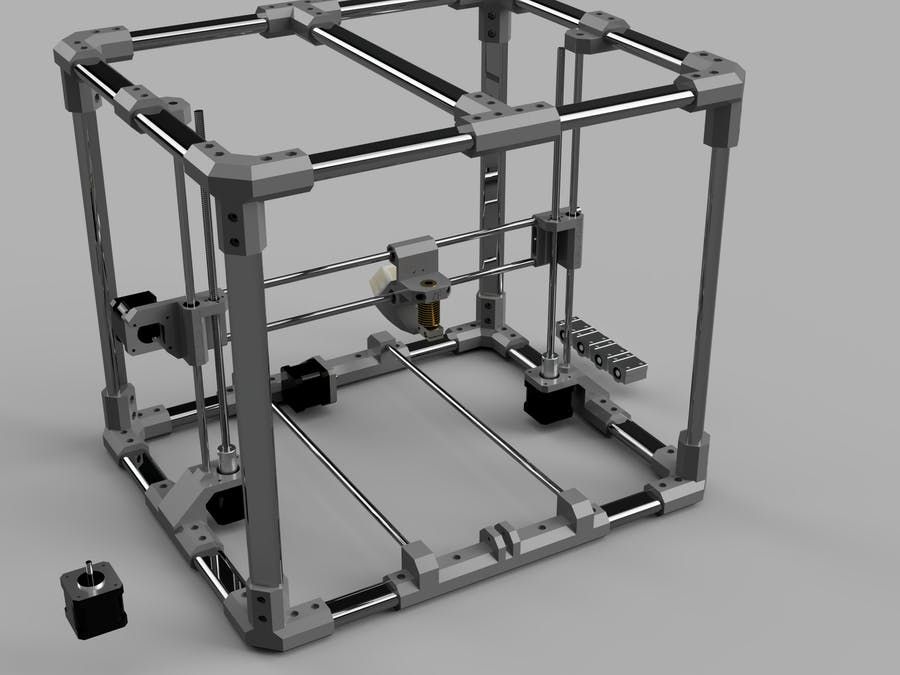
Heading into the project I knew I wanted to eliminate the leadscrew driven Z axis design that was and still is the industry standard for the market segment.
There are many drawbacks of the leadscrew design that can cause printing artifacts. These drawbacks are a combination of design and manufacturing defects of the components used. The leadscrews can have pitch deviation throughout the length causing the layer height to vary. The runout is also a major contributor to print defects. The runout will cause what is known as “Z wobble” making the side of prints uneven and “wavy” mimicking the runout of the leadscrew. The basic “prusa” design uses two open loop stepper motors to drive a leadscrew at each end of the X gantry. The open loop control does not actively synchronize the motors which can lead to skewing of the X gantry in the XZ plane.
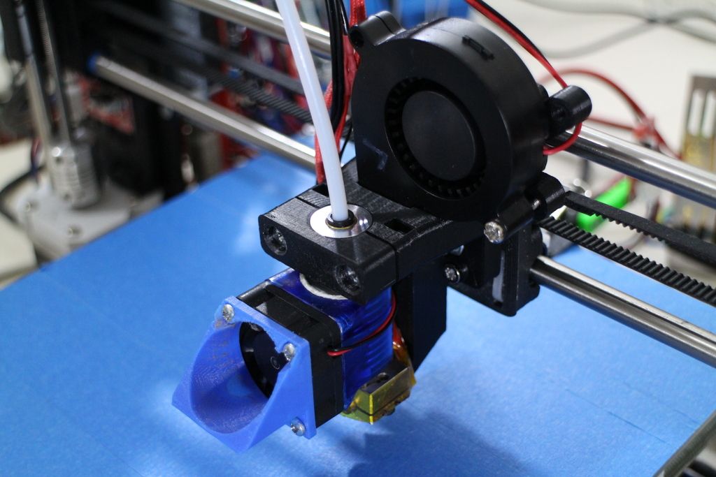
To solve these issues I designed a belted reduction setup with a single motor. The reduction is 5:1 ensuring the natural detent torque of a Nema 17 motor with greater than 50oz-in torque rating can support the mass of the X gantry when powered off. The tension of the Z axis belts also adds rigidity to the X gantry compared to relying on the mass of the X gantry to pre-load the system in a leadscrew setup.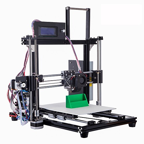
This design has proven to be very effective and reliable. I have tens of thousands of print hours across twenty custom printers using the design with zero defects or mechanical failures.
Motion Platform
motors: Nema 17 (wantai)
belts: genuine gates
Y AXIS - 2:1 belted reduction; Motor: Nema 17 72 oz-in. 1.2 amp; Main axis drive belt: 9mm gt2 2mm ptich
x axis - direct drive; motor: nema 17 60 oz-in 1.5 amp; belt: 6mm gt2 2mm pitch
z axis - 5:1 belted reduction; motor: nema 17 68 oz-in 1.5 amp; drive belt: dual 9mm gt2 2mm pitch
Linear setup
y axis - dual misumi 16mm linear rod; misumi lmu16 bearings
x axis - dual hiwin mgn9 rail; hiwin mgn9c carriages
z axis - dual misumi 16mm linear rod; misumi lmud16 special length bearings
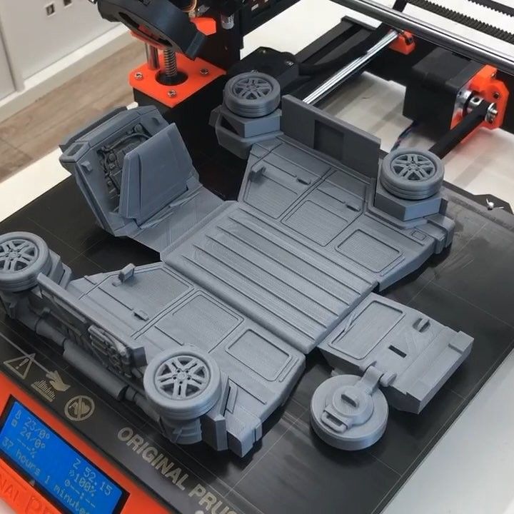
Design
I wanted to build a printer that was far more rigid and robust than other commercial desktop 3D printers. The frame is constructed from 1” X 2” 80/20 extrusion.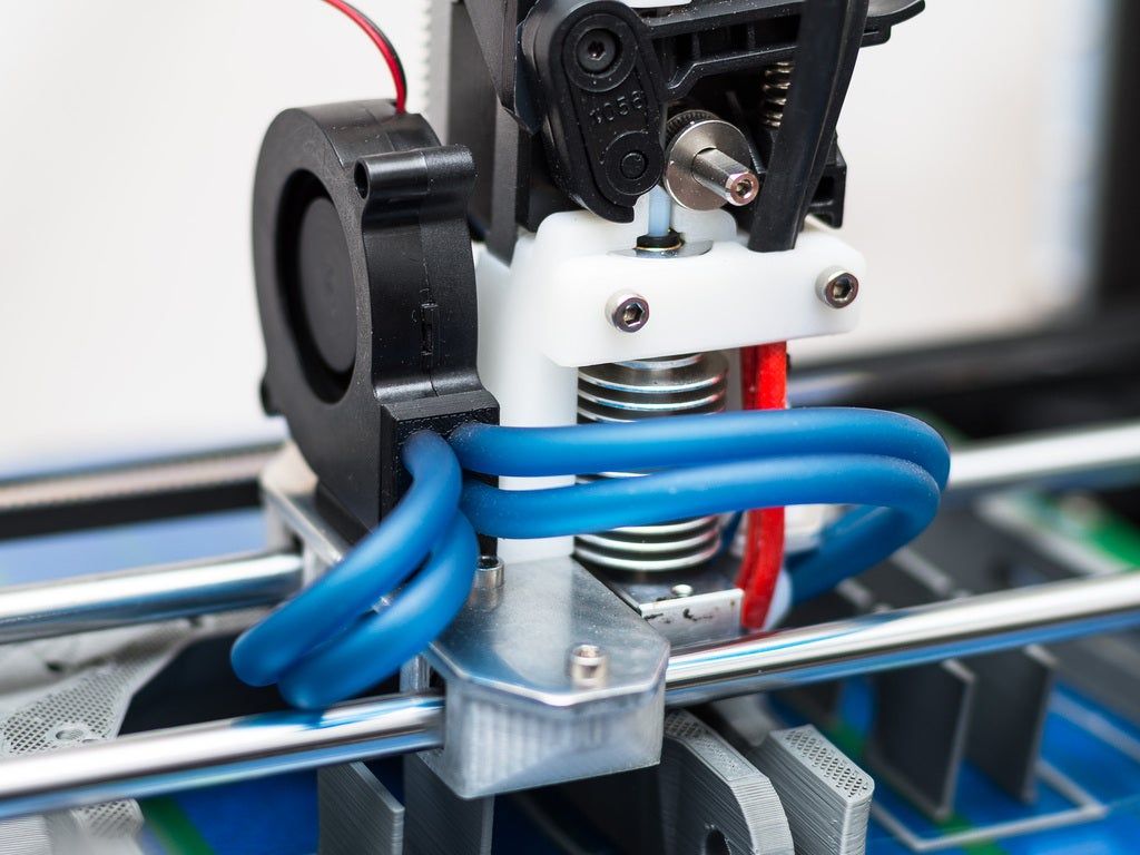 I machined all of the extrusion on my CNC mill to produce a precise and easily assembled frame. After completing the first printer I decided to test the market and produce a limited number of kits aimed at serious 3D printing enthusiast. I went through the design eliminating components and consolidating sub-assemblies into as few parts as possible. For example, the Z axis motor mount was originally a sub-assembly consisting of three separate plates sandwiched together using 3D printed spacers. The mount was also susceptible to bending under the tension of the reduction belt. This assembly required many screws and a tedious assembly process. The mount was re-designed to add rigidity and reduce the part count down to only two plates. The prototype printers also had many machined parts which would add time and costs to the manufacturing of the kits. I substituted many machined parts with 3D printed ones. The Y axis motor mount was also redesigned so that it could be laser cut and bent from 1/8” aluminum plate.
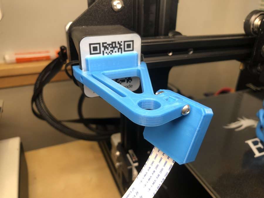 To aide in the assembly process various features were added throughout the design such as imprinted part identification, shallow milled pockets for the Z up rights, and dowel pins where part alignment is critical.
View fullsize
View fullsize
View fullsize
View fullsize
Moso3D | Making 3D printing easy
Moso 3D
Automatic 4 Tool Changer
Toolchanging means truly being able to print in multiple materials, even if they have different requirements, because each material has its own extruder.
Thanks to its custom design and simple setup, the Moso MT is the ideal solution for printing any project.
Get a quote
Making 3D printing easy
Toolchanger
Being able to change extruders on-demand during a print enables true multi-material printing. This printer allows you to use different nozzle sizes and multimaterial in the same print
Multimaterial
Printing in more than one color or material will no longer be done by pushing different filaments through a single nozzle, which limits a print to materials that extrude under similar conditions and temperatures.
Autolevel & Autoffset
Autoadjust bed leveling and offset of all tools to get an easy & reliable prints without effort. A touch user interface guides you through the entire setup and printing process.
KEY FEATURES
- Four extruders /Tools
- Auto-leveling & Auto-offset
- Heated chamber & bed
- Humidity controlled storage
- Hepa Filter
- Automatic sliding door
Intuitive Interface + Assistant
Hepa filter + Carbon filter
Easy access to the tools
Humidity controlled material storage
Heated chamber 70ºC
Get a quote
Print Volume 300 x 300 x 300 mm
External dimensions 806 x 737 x 862 mm
Printing technology FFF
Bed temperature 150ºC
Chamber temperature 70ºC
Leveling system Automatic
Weight 90 Kg
Maximum power 2000W
Moso MT Brochure
Extrude it all
We are developing new customs tools that allow you to print a wide range of materials.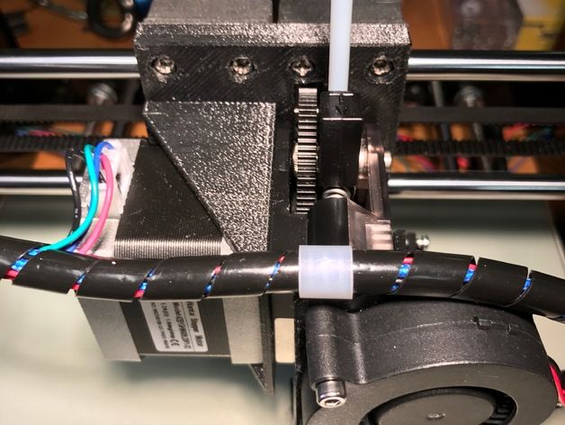 Extruder tools with auto-alignment and auto-offset calibration for easy use and high reliability
Tired of switching between nozzles in each printing?
Now you can have all of them installed and just select your desired one in the slicer.
Choose your Tool
Discover the desktop 3Dprinter with an automatic multitool change system and bamboo enclosure.
Thanks to its custom design and simple setup Most MT ECO is the ideal solution for 3D printing keeping in mind sustainability.
Moso MT ECO
PP is a hard to print material, prone to warping and a difficult bed adhesion. Get rid of all these problems with this combination of printing surface and specially designed PP material for easy 3D printing
PP Pack
All you need to print soluble supports with great reliability. Moso soluble Pack includes a unique soluble support materials VXL 90, VXL111 and a custom designed solvent by XIONEER.
Print effortlessly, adhere to most materials, and dissolve quickly.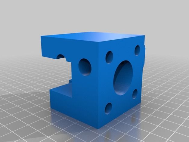
Soluble Pack
All you need to print soluble supports with great reliability. Moso soluble Pack includes a unique soluble support materials VXL 90, VXL111 and a custom designed solvent by XIONEER.
Print effortlessly, adhere to most materials, and dissolve quickly.
Soluble Pack
Moso 3D Forest
With each Moso 3D product, we will plant trees to reduce the CO2 footprint. We finance small agroforestry projects in different countries around the world thanks to Treedom.net platform.
Our customers will be able to follow the history of the project to which the trees will contribute, see pictures when it’s planted and know the exact place where it will grow.
More info
The first layer does not stick when printing on a 3D printer?
Home » Articles » Problems with 3D Printing » First layer not sticking when printing on a 3D printer?
First coat not sticking?
This problem must be urgently solved, since the quality of the model construction depends on the first layer serving as the basis, or rather on the reliability of its fastening to the desktop.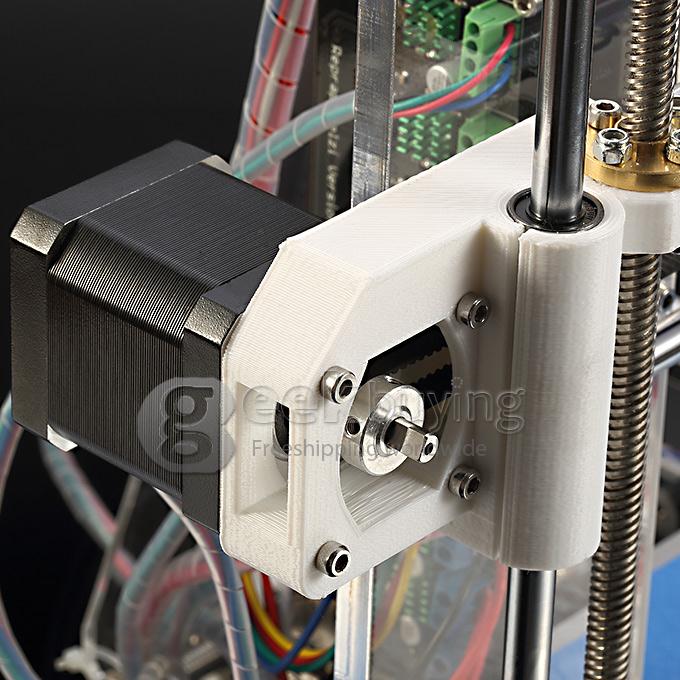 There are several reasons for its appearance, consider the most common of them.
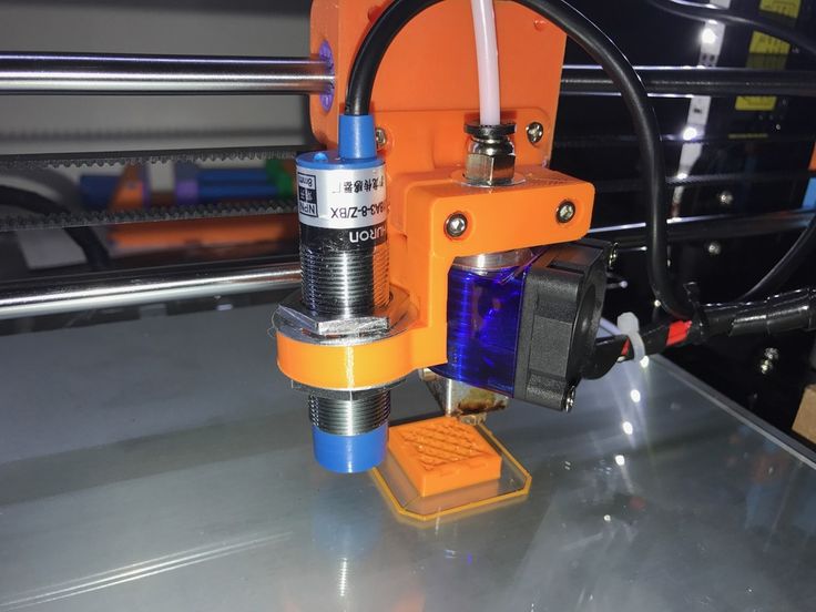
1. Skewed print bed.
The print platform must be in an absolutely flat horizontal position before starting the 3D printer, otherwise the distance between the nozzle and it will be uneven. To align it with the design of the printer, screws and handles are provided, as well as a special function - the "Bed leveling wizard". It can be found in the "Tools" menu and can be used to step-by-step configure the platform by setting the required parameters.
2. Wrong working distance calibration.
Leveling the worktable is only half the battle, it is important to place the extruder nozzle over it correctly so that there is enough free space for the filament to exit, but at the same time the filament seems to be pressed into it. To do this, you need to use the calibration function of the working platform, which most modern models have. If your 3D printer does not have this feature, then you will have to manually calibrate the desktop - fix the print head in a static position and stop the motors, and then adjust the distance by moving the print unit.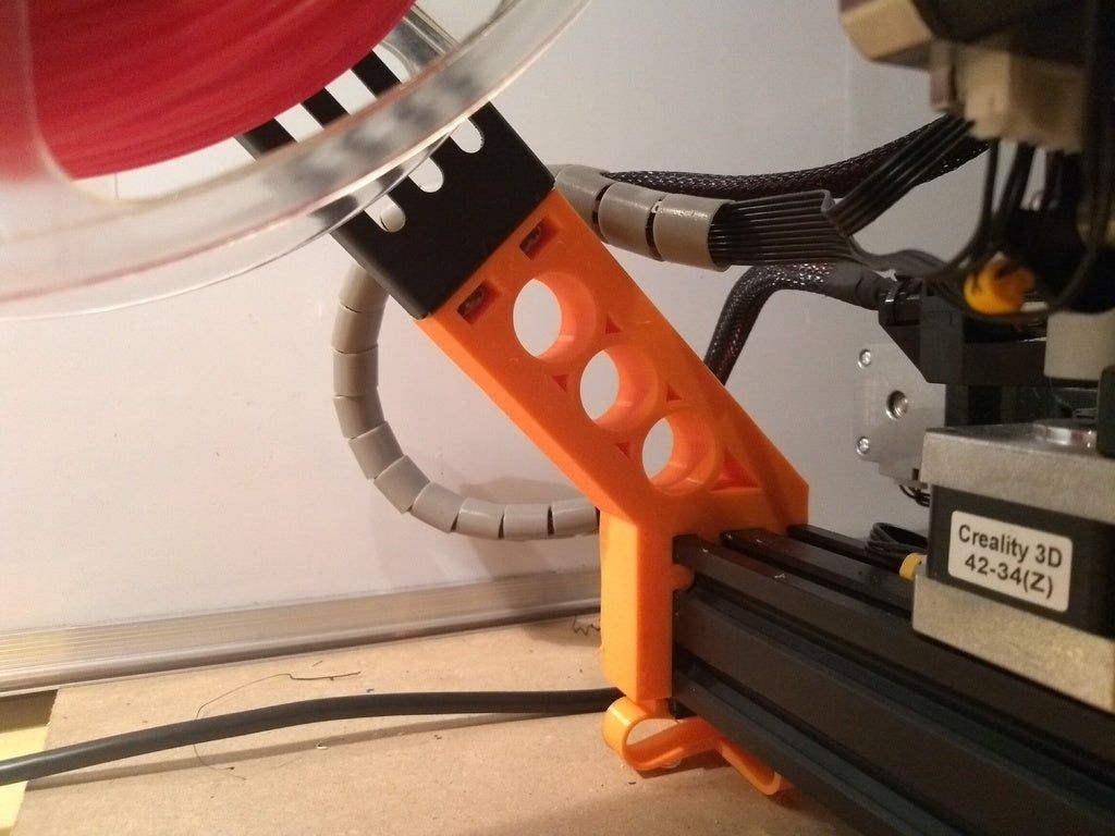
Another way to calibrate the 3D printer desktop is software adjustment, which is highly accurate and easy to use. You will find all the necessary parameters for it in the menu. All you need to do is to correct the indicators in the slicer G-Code. Initially, it is better to set small distance values, and then control them by test printing and, if necessary, make changes to them.
When calibrating the 3D printer desktop, please note the following:
- If the nozzle is at a considerable distance from the build platform, there will always be a risk of the filament coming off during printing due to insufficient pressure on it.
- Insufficient clearance between the build table and the nozzle can cause damage to them and poor print quality due to lack of space for the filament to exit and form a 3D model.
- A normal distance between the nozzle and the work table will ensure that the layers are formed correctly over the entire surface area and that they adhere well to each other.
Consider the above recommendations and do not ignore the need for calibration.
3. Print speed selected incorrectly.
An incorrectly selected print speed can break the adhesion between the layers of the model being grown. This is especially true for the output of the first layer. Its insufficient adhesion to the working surface indicates too high a print speed. The output of the filament thread can and should be slowed down using the corresponding First Layer Speed function from the Edit Process Settings menu. When printing the first layer, reduce the speed settings set by the program by half.
4. Wrong operating temperature setting.
A 3D model may warp if it cools quickly. High-temperature ABS plastics “sin” with this, which need to be given more time to cool than other materials. Cooling models provide special fans. They have their own operating parameters, which users can change on their own.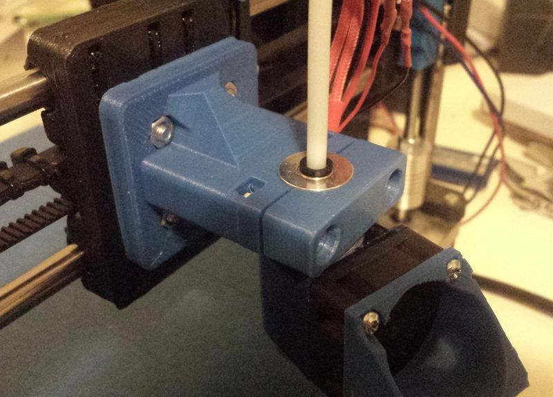 With rapid cooling, there is a risk of plastic peeling off the desktop, which provokes deformation of the 3D model. Switching off the fan is usually enough to prevent this. This will allow the first layers of the model to cool slowly and reduce the risk of deformation to zero. To turn off the fans, the Cooling function is provided from the Edit Process Settings menu. Some models even allow users to specify a different fan speed for the first layer and each subsequent layer. When printing a 3D model with high-temperature ABS plastics, the fan can be completely turned off and the platform heating turned on, which eliminates the risk of deformation of the first layer. This feature is found in the Edit Process SettingsTemperature menu. To turn on the platform heating, you need to specify the temperature parameters of the first layer of the future model. In order not to make a mistake with them, we recommend using the established material heating standards that are used for 3D printing. In the presence of drafts, additional protection of the working platform from cooling is required.
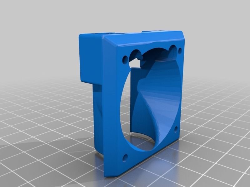
5. Incorrect material selection for platform protection.
For both professional and amateur 3D printing, different filaments are used, so their reaction to the consumables used - tape, glue, etc. difficult to predict. To avoid poor quality printing, you should use a material that is ideal for covering the work surface, which can be purchased at a specialized store. It is allowed to perform 3D printing directly on the desktop without auxiliary materials, provided that it is perfectly clean. To enhance the adhesion of 3D plastic to the desktop, it is allowed to use pieces of tape, glues, sprays, hair sprays and other similar materials.
6. Printing a model with a small bottom surface.
If you want to grow a 3D model with a small bottom surface, use the brim function from the Additions ---> Use skirt/brim menu, which will allow you to artificially enlarge it by printing a "hat" around it. An alternative would be to use a previously printed substrate, which will serve as the basis for a future 3D model.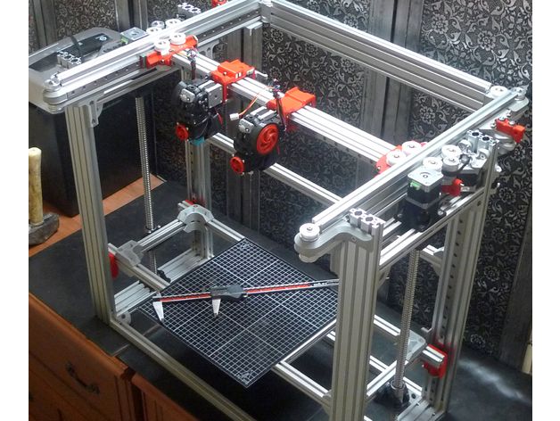
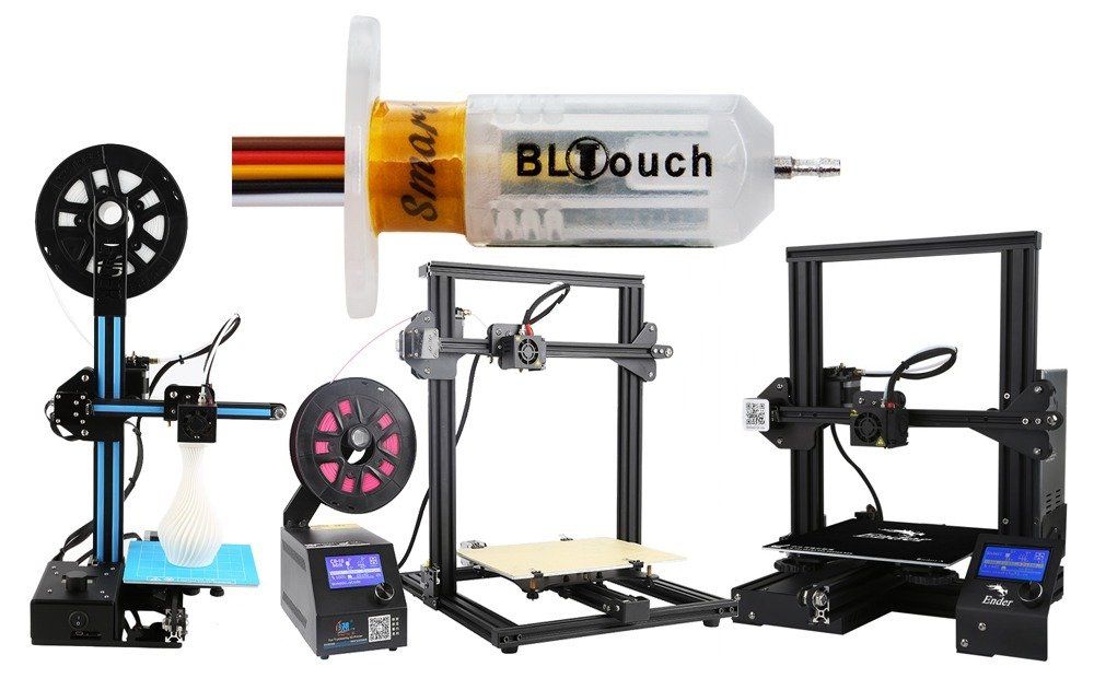
How to assemble the Creality Ender-3 V2 / Amp
The Creality Ender-3 V2 3D printer is delivered in a semi-unassembled box. After the purchase, you need to go through a small quest and assemble the printer. Follow our instructions and you will get a ready-to-use device!
Contents
- 1. Parts to assemble
- 2. Housing assembly
- 2.1. Installing the Z-pillars
- 2.2. Installing the Z-axis limit switch
- 2.3. Installing the Z-axis shaft on the motor
- 2.4. Installing the Z motor
- 3. Assembly of the X-axis unit
- 3.1. Installing the extruder block on profile
- 3.2. Installing the Printhead and Fixing the Belt
- 3.3. Installing the X-axis tensioner
- 3.4. Installing the X-axis on the stands
- 4. Installation of the top portal profile
- 5. Installing external modules
- 5.
 1. Installing the spool holder
 - 5.2. Display installation
- 5.3. Installing the indicator wheel and other parts
- 5.4. Wiring
- 5.
- 6. Printer preset
- 6.1. Tightening X and Y belts
- 6.2. Connecting the network cable
- 6.3. Plastic loading
- 6.4. Table level adjustment
- 7. Printing test model
1. Assembly parts
- 1× Printer disassembled
- 1× Manual
- 1× PLA (test roll)
- 1× Spare parts kit
- 1× Key set
- 1× Set of nylon ties
- 1× Nozzle cleaning needle
- 1× Spatula
- 1× Cutters
- 1× microSD card (8 GB)
- 1× USB microSD card reader
- 1× Mains cable
2. Body assembly
For threaded connections, use the hex wrench set supplied with the printer or use your favorite screwdriver. The manufacturer may have put in a few spare screws. If after assembly you still have extra parts, this does not mean that the printer was assembled incorrectly.
2.1. Installing the Z Axis Stands
What you need:
- 1× Printer Bed Assembly
- 2× Vertical Portal Post
- 4× Screw M5×45
Turn the printer base on its side. It is much more convenient to mount the portal racks on its side.
Pay attention to the holes in the uprights. They are not symmetrical. In the left column, two holes are located at the bottom at the same level, and in the right column, they are vertically above each other.
Attach the standoffs with the screws on the bottom of the printer.
2.2. Fitting the Z Axis End
What you will need:
- 1× Z Axis End
Install the trailer into the bottom of the rack so that its protruding edge rests against the base of the platform. Turn the nuts on the end cap vertically and insert it into the profile, then tighten. The nuts must turn and secure the limit switch. If they don't turn, loosen and re-tighten the screw.
2.3. Fitting the Z shaft to the motor
What you need:
- 1× Z motor assembly
- 1× Z Shaft
Insert the shaft into the coupling until it stops. Tighten the top and bottom coupling screws.
2.4. Z Axis Motor Installation
Items Needed:
- 1× Z Axis Motor with Shaft Assembly
- 2× Screw M4×18
Place the motor and shaft behind the left printer stand.
Attach the motor with two screws to the printer stand.
3. Assembly of the X-axis unit
3.1. Installing the extruder block on the profile
What you need:
- 1× X-axis belt
- 1× X-axis extruder and motor assembly
- 1× X-axis guide
- 2× Screw M4×16
Pass the strap through the safety clip. The belt should be turned with the ribbed side towards the toothed pulley.
Attach the X-axis guide to the X-axis extruder and motor assembly. The holes on the guide are not symmetrical. If the holes don't line up, turn it right side up.
Screw the extruder and motor assembly to the rail through the holes on the back of the plate.
3.2. Mounting the print head and fixing the belt
What you need:
- 1× X-axis extruder and motor assembly
- 1× Z axis carriage
- 1× Print head assembly
- 1× Screw M4×16
Slide the printhead onto the X-axis profile. Pay attention to the position of the printhead relative to the extruder.
Screw the second carriage onto the X axis. Tighten only one screw.
3.3. Installing the X-Axis Tensioner
What You Need:
- 1× X-Axis Block Assembly
- 1× X axle tensioner
- 1× Screw M4×16
- 1× Screw M4×14
Loosen the tensioner adjusting screw and pull the unit out of the housing.
Pass the belt through the profile under the two carriage wheels so that the teeth of the belt are facing towards the profile.
Attach the other end of the strap to the print head.
Pass the loose part of the belt through the pulley. Note that the deep groove of the block faces the underside of the axle.
Attach the free end of the strap to the printhead.
Insert the plastic housing of the tensioner onto the mounting block. Pay attention to the slot in the body. It should face away from the print head.
Fasten the housing to the profile with an M4×16 screw.
Secure on the back with a countersunk screw. Do not overtighten this screw.
Screw the adjusting screw onto the protrusion of the unit mount.
3.4. Installing the X-axis on stands
The X-axis with the extruder unit is assembled. Put it on the stands.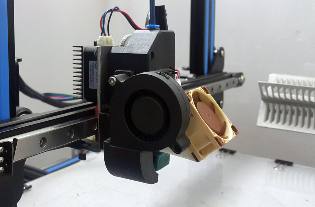 The print head must be on the front side.
4. Installation of the portal top profile
What you will need:
- 1× Portal bar
- 4× Screw M5×25
Screw on the top of the portal.
5. Installation of external modules
5.1. Installing the spool holder
What you need:
- 1× Plastic part of the spool holder with nut
- 1× Spool holder metal part
- 2× Nut M5
- 2× Screw M5×8
Screw the nuts onto the metal holder bracket.
Install the nuts along the profile groove. Place the metal holder into the groove and tighten the screws. The nuts should turn and secure the bracket.
Remove the large nut from the plastic holder, thread it through the metal bracket and tighten the holder nut.
5.2. Display installation
What you need:
- 1× Display module assembly
Remove the display from the bracket.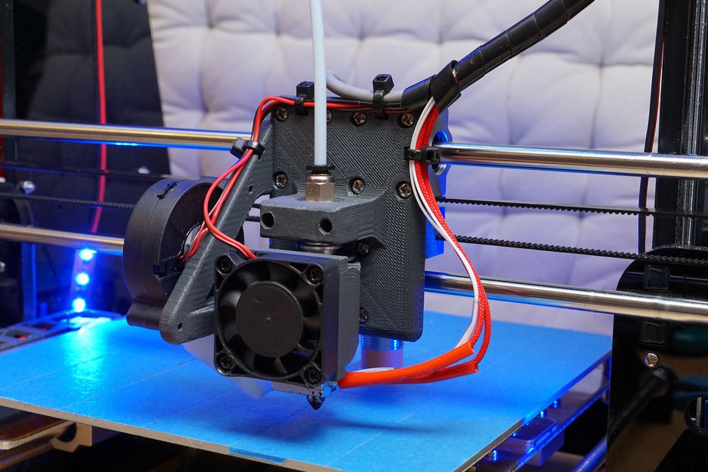
Turn the nuts parallel to the groove in the profile. Attach the fastener to the profile and tighten the screws. The nuts should turn into the slots and secure the display bracket.
Connect the display cable to the connector.
5.3. Installing the indicator wheel and other parts
What you need:
- 1× Indicator wheel
- 1× Fitting
- 2× End caps per profile
Screw the fitting onto the extruder. Tighten it with a wrench.
Slide the indicator wheel onto the motor shaft.
Place the caps on the top profile of the portal.
5.4. Wiring
Insert the Teflon tube into the extruder fitting all the way. Install latch.
Connect the extruder cable to the motor. There is a label with the letter "E" on the cable.
Connect the X axis motor cable. There is an “X” mark on the motor.
Connect the X-axis limit switch cable.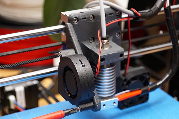 There is an "X" mark on the cable.
Connect the Z axis limit switch cable.
Connect the Z axis motor cable. There is a corresponding mark on the cable.
Tie the wires that go to the Y axis with a tie. The protruding end of the tie can be cut off.
6. Printer preset
6.1. Tightening the X and Y Axis Belts
Turn the X and Y Axis adjusting screws until the belts are tight. Don't drag them! Belts should not sag, while the axles should move freely.
6.2. Connecting the network cable
Plug the network cable into the socket.
Check that the switch on the power supply is in the "230V" position.
6.3. Loading plastic
Use the encoder on the screen to enter "Prepare".
Select "Preheat PLA" if you are printing with PLA or PETG, and "Preheat ABS" if you are printing with ABS or other high temperature plastics.
Exit to the main menu using the "Back" item.
Wait until the temperature reaches the set temperature.
Cut off the end of the plastic thread. It is better to cut it obliquely so that the end is sharp and more convenient to get into the fitting.
Thread the extruder.
Rotate the knob until plastic comes out of the nozzle.
6.4. Adjusting the table level
Screw in the table screws so that the table is as low as possible.
Use the encoder on the screen to enter "Prepare".
Select "Auto home". The printer will set the nozzle to the zero position.
Then turn off the motors with the "Disable stepper" command.
Place a piece of paper between the nozzle and the table. Unscrew the screw until the nozzle begins to scratch the leaf.
Move the print head and table by hand. Repeat this operation in each corner of the table to set the most even position in the horizontal plane.