Stepper disabled 3d printer
let’s fix it! – 3D Solved
Altough I think I know my way around a 3d printer, it always scares me when a machine fails due to a potential hardware issue. In contrast to changing some obscure setting in the slicer, my heart tends to skip a beat when I’m dealing with mechanical and electrical parts.
Sooner or later, you will have to deal with a stepper motor not working correctly. If you are like me, you certainly prefer to do some research before trying potentially irreversible things. Although we are going to dig deeper into each cause, these are the most common causes of a stepper motor not properly working.
A 3D printer’s stepper motor may not be working due to insufficient electrical current, a loss of continuity along with the wiring or a connector, or a faulty stepper motor driver or control board.
Of course, this brief summary is not very useful when it comes to solving your issue at hand, so let’s get started!
Table Of Contents
- How to fix a Stepper Motor that is not moving
- Check the stepper motor driver board
- How to Fix a Noisy/Clicking Stepper Motor
- Other frequently asked questions
- Check out our recommended products section
How to fix a Stepper Motor that is not moving
When it comes down to issues related to non-functioning hardware, the recommended path to solve them is always going from the simplest to the most complicated possible solution. It is useless to check the firmware settings or modify advanced configurations of our printer if we do not first verify that the machine is turned on. Although it sounds silly, most problems are usually solved via almost trivial and very basic checks. when dealing with stepper motors, this is not the exception to the rule.
Before we start tracking down the problem that does not allow the motor to move, I will ask you a question: is the problem being caused due to the stepper motor itself?
Many users don’t know it (and why should they?), but the 3d printer’s firmware is set to prevent the extruder motor from moving when the hotend is cold. That means that before you try to move it, you must pre-heat the hotend to a temperature above the minimum (I recommend 200 degrees, just to be safe).
Now that we are aware of this, let’s try to fix that annoying motor!
Stepper motor not receiving electrical current
First of all, you must check that the motor receives electrical current.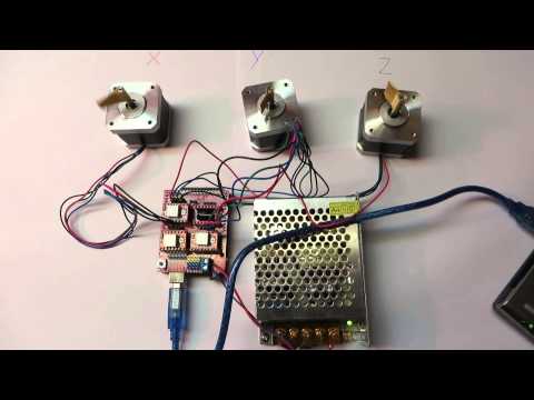 To do that, you don’t need a multimeter or any particular tool, just turn the printer on and try to move the motors from the menu.
On Marlin-type printers, select “Prepare” -> “Move axis” and select the axis of the motor that is not working. Order a sufficiently long movement, such as 150 mm in the X / Y axes, or 100 mm in the Z-axis. If during the movement you can move the motor using your hand, it means that the magnetic field is not being generated within the motor, which is necessary for its operation. Since the field is generated by an electric current, it is most likely a power problem.
Check the voltage supplied by the source with a multimeter. Some printers run at 12V while others need 24V. The reading should be stable at all times. If the power source terminals are not delivering the necessary voltage, the printer components will start to fail. Replace the power supply if necessary.
Having done so, make sure that the motor connection plugs are correctly connected, and verify that there are no bent pins. Try checking the continuity of each wire using a multimeter (the video below shows you how to do it). Failure in any of the wires will result in the engine not working properly. If you find any wire that does not pass the continuity test, replace the connector.
Check the stepper motor driver board
The next step in finding the cause for the failure is verifying the driver. Typically, a Pololu A4988 is used. This small board regulates the power of the stepper motor and it serves as the link between the control board and the stepper motor.
Wiring schematic of an Arduino Uno, a Pololu A4988, and a stepper motor. SourceTry moving the driver to another plug and see if the problem is transferred to the engine where you connected that driver.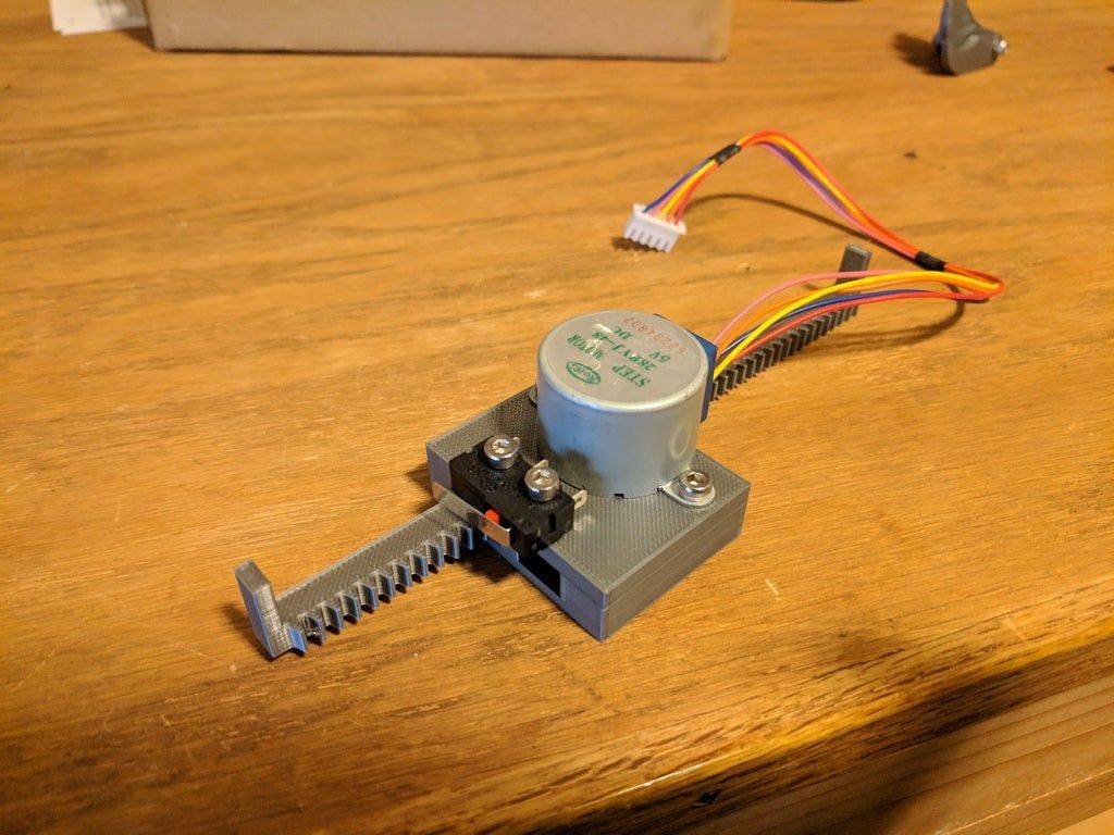 Be very careful when connecting the driver, as its pins must be oriented correctly (look for the “Enable” pin on both the driver and the board and match them). Placing it upside down will cause the driver or control board to burn out.
If you find that the problem was the driver, replace it with the same or an equivalent one. There are quieter and longer-life models, but they are much more expensive than the A4988 driver.
Now it is time to check the control board. RepRap 3d printers often use an Arduino Mega + Ramps combination as they are the cheapest and most reliable version you can get. You will need to get another board to test if the problem still occurs.
How to Fix a Noisy/Clicking Stepper Motor
Increase motor driver voltage to achieve the required torque
When a stepper motor has to generate a really big torque (higher than what it can deliver), it will stop moving, but the magnetic field continues to demand the motor shaft to spin.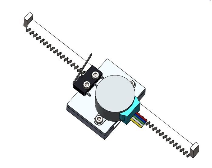 This can be heard as one or more “clicks” within the engine.
Since the control board has no feedback regarding the extruder position, printing continues as if nothing happened and the step is “lost”. This produces a displacement of layers in the object, or sectors without deposited filament when the motor that loses steps is the extruder motor.
The most common cause of loss of steps in the movement axes is a low voltage set in the motor driver. In order to increase the voltage, the drivers have a small potentiometer on the top. Using a ceramic tip screwdriver, turn the potentiometer clockwise. At the same time, the delivered voltage should be read with a multimeter.
The necessary voltage varies on each printer, type of stepper motor, and load required by the motor. Z-axis and extruder motors oftentimes will require more tension than the others. Some people perform calculations to determine the voltage according to the motor used, but in my experience this must be done empirically, increasing the voltage value until a reliable operation is reached.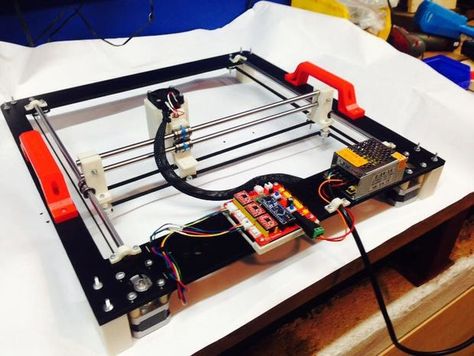
Other common causes
- Lack of lubrication in the guides: this makes the movement demand a greater torque.
- Excessive tension on the belts: the belt pulls strongly on the motor shaft, making it unnecessary tense. The straps should be relatively tight, but make sure not to exaggerate it.
- Low extrusion temperature: if the filament is not hot enough, it will not flow smoothly through the hotend, causing the pressure required for extrusion to increase. A temperature tower is the best test in order to establish the optimum printing temperature.
- Failure in the barrel cooling: if the heat “rises” along the barrel, it causes the filament to become soft. The upper part of the filament should act as a piston, so it must be as cold as possible. When this fails, the motor is forced more, leading it to lose steps and generate a jam in the nozzle. Adding a heat sink and/or a cooling fan may help with this issue.
- The set speed is excessive: the acceleration required from the engine must be within its capabilities. When the motor fails to meet the demand for movement, it loses steps. The X / Y axes are the most affected by this problem.
- Backlash on the shaft: if the belt is too loose, or the guide system allows a small amount of backlash, the first steps in a change of direction will be lost, causing a distortion of the object.
- Driver overload: As drivers handle very large currents, they need to dissipate large amounts of heat. For this, aluminum heatsinks are usually attached to the main chip of the driver. When the heat is excessive, the driver starts to malfunction and one of the most frequent symptoms is the loss of steps in the motor. To avoid that, I recommend placing a cooling fan pointing directly at the drivers.
Other frequently asked questions
Can a Stepper motor get too hot?
If you touch the motors during a very long print, you will notice that they can get quite hot. This happens because part of the power generated by the motors is transformed into mechanical energy and another part is lost as heat.
The motor housing and its internal components are designed to withstand a lot of heat, but if a maximum temperature is exceeded, they could be damaged.
The maximum operating temperature of a stepper motor is always specified on the datasheet of the specific model. Although the specific values varies quite a lot, it usually falls in the 70°C-100°C range.
As a rule of thumb, we could say that if you cannot touch the stepper motor, it is because it is clearly too hot. Although this is relative, it is a good starting point. Regulate the voltage in the drivers at a midpoint, in which the operation is as expected but without increasing the temperature too much.
Once you have a good configuration, I recommend that you take note of the values for each stepper motor. In case you need to replace a driver, you will not have to redo this test.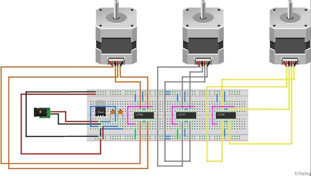
Do Stepper Motors Require Maintenance?
Stepper motors are maintenance-free. It is not necessary to go into details, but unlike common direct current motors, they do not have brushes or parts in contact that can wear out. Just make sure to keep it dust and dirt-free. If you use hairspray to improve bed adhesion, be sure to cover all the electronic parts before spraying it.
How to Replace a Stepper Motor
If you got here without finding the problem, the stepper motor is most likely out of order and you need to replace it. For doing so, it is important that you know that the NEMA 17 designation (the most used in 3d printing) only refers to the distribution of the mounting threaded holes. Within this range of engines, there are countless variants that may or may not match the specifications you need.
Before purchasing a new motor, check with the printer manufacturer for the specifications regarding:
- Operating voltage
- Torque
- Degrees of rotation for each step (number of steps per revolution)
- Height of the motor (to make sure it fits in the same place as the previous one)
We created a recommended products section that will allow you to remove the guesswork and reduce the time spent researching what printer, filament, or upgrades to get, since we know that this can be a very daunting task and which generally leads to a lot of confusion.
We have selected just a handful of 3D printers that we consider to be good for beginners as well as intermediates, and even experts, making the decision easier, and the filaments, as well as the upgrades listed, were all tested by us and carefully selected, so you know that whichever one you choose will work as intended.
Pushing the Limits of Stepper Motor Control in 3D Printing
A guest blog by Jan Kotarski
Theory
In the 3D printing community, newcomers are often having a hard time understanding how stepper motors are really driven. Questions like “voltage rating for my motor is 4.6V, can I use it if my printer has a 12/24V power supply?” and similar pop out from time to time.
This is because most of the electronics we use every day use constant voltage supply with variable current and that’s what we are used to think about. A 12V LED strip will be powered by a stable, controlled 12V and the current consumption will increase as the number of diodes – the load – gets bigger.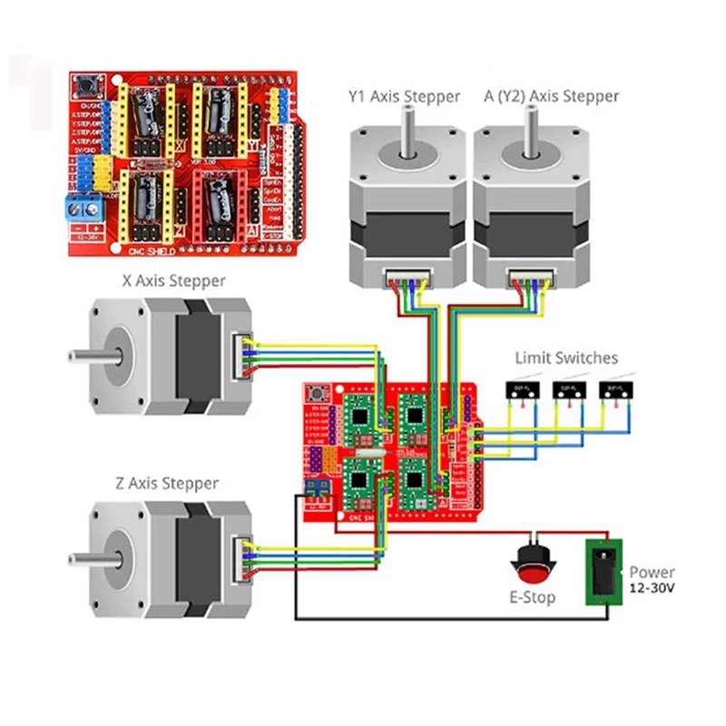
Stepper motors are powered in a reverse way – the current is constant/controlled (more on that later) and the voltage required varies together with the load. That’s why in 3D printing 12V power supplies were replaced by 24V or even higher voltage supplies – because (apart from other benefits) this way the printer can deliver more power to the motors, reach higher movement speeds and be more dynamic, despite the set motor current staying at the same level.
But the typical power supply delivers constant voltage. How is it converted to regulated, controlled current? It’s the job of the stepper motor driver, like the TMC2208.
The current regulation is achieved using a technique called PWM (Pulse Width Modulation). Voltage is very quickly switched on and off using MOSFET transistors in a manner that results in the current flowing at a desired level. But this current control method will not work with a simple resistive load – the current regulation can only be achieved when driving coils – and they, together with magnets or other coils are making the stepper motor rotate. A coil – an inductor – has an interesting property – it “slows down” the current flow, adding “inertia” to it. That means that if a voltage is applied, the current flowing through an inductor will not rise immediately – but slowly. The same thing happens when the voltage is disabled – the current will not immediately drop to zero amperes but will decrease over time.
By the way, LEDs are actually current-controlled too – but in the case of a simple LED strip, a resistor is enough to regulate the current, so finally a LED strip is working as a constant voltage device.
Practical measurements
The described current control method can be seen clearly on actual measurements:
The yellow curve represents current flowing through a motor coil, the cyan line shows the voltage being switched on/off. This measurement was taken during standby, when the motor was not rotating, but holding its position. The current is pretty much constant and the voltage is regularly switched on for a short period of time and then turned off again.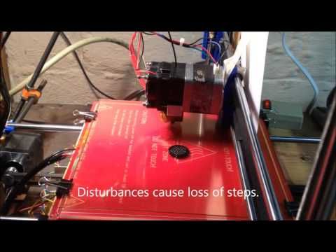 Please note that this switching is happening over 30.000 times a second!
When the motor starts moving, that’s when the interesting stuff happens. The shape of the current waveform is not flat anymore – it’s a sine wave. To rotate the motor, the current needs to be changing to alternate the magnetic field, which results in motion. This principle is true for all brushless electric motors. The TMC2208 is actively measuring and regulating the current, creating a sine current shape with set amplitude and the effective voltage varies accordingly. Rotation speed depends on the frequency of the current sine wave.
Don’t worry about the waviness of the voltage measurement – it’s an artifact. The amplitude – seen at the bottom of the screen – is more or less equal to the supply voltage which I was using (32V). The RMS value is an indicator of “how much” effective voltage is delivered to the motor coil. In this case, the measured/calculated value is not very precise, but it shows that at this speed we deliver less than 40% of the nominal supply voltage.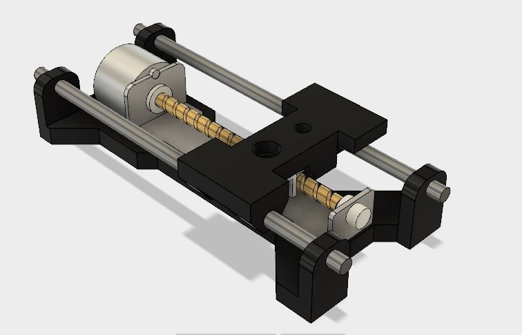
When we zoom in, we can clearly see the mentioned special property of an inductor:
When the voltage is on, the current is rising, but quite slowly compared to how fast the voltage is rising/falling. When we turn off the voltage, current flowing through the coil falls, but again – quite slowly. Before it goes too low, the driver turns on the supply and the current goes up again. This is essentially how we keep the current at the required level. Please also note that the time how long the MOSFET switch is conducting (how long the voltage stays ON) depends on the “position” on the sine wave. When we look at the sine wave, we can see regions that change slowly (near the top/bottom) and which change faster (near zero on the Y-axis). If we want the current to follow this shape, we simply need to apply the voltage for a bit longer in the “fast region” of the sine wave!
The small irregularities, deviations from ideal, smooth sine shape are called ripples and are always present when a coil current is controlled with PWM.
Effects of the motor load
At this point, one very important question arises – what causes the required voltage (actual power delivered to the motor) to vary with changing load? That thing is called BEMF – Back ElectroMotoric Force – the inherent property of every electric motor. I don’t want to get into the physics details of this phenomenon in this article – simply speaking, the motor coil during spinning is generating a “counter” voltage, which is fighting with the voltage that we are applying from the power supply to the motor, that’s why it is called Back EMF. The higher the speed (or load), the higher the BEMF that we need to fight with.
BEMF is affected by three main factors:
- motor coil inductance – the smaller, the better;
- set current – the higher the current, the stronger the motor is, but so is generated BEMF;
- speed/mechanical load – of course the BEMF increases together with the load.
That’s how the sensorless homing using StallGuard works – it measures the BEMF!
Actual influence of BEMF
On the measurement below, we can see an acceleration move and close-ups of two regions – with low/high speed.
When the speed was still quite low, the motor controller still had plenty of headroom to nicely regulate the current, so the sine wave can be considered ideal. But if we zoom in a bit later, we can see that the current looks more like a triangle, and the voltage is applied not very precisely. That’s because the controller had no voltage headroom to properly regulate the current and in effect, the sine wave gets distorted, although the motor is still operating.
Now that we understand how a stepper motor is controlled, we can get to the next point and answer the last question – what happens when the BEMF is so high that the mentioned “counter” voltage is getting too close to the supply voltage? One might guess that the motor will start losing steps – and that’s true, but not immediately! I was honestly surprised by how well the drivers and motors are handling extreme speeds.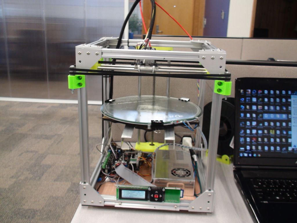 Let’s take a look:
This is the current flowing through the motor coil during a full move using a 24V power supply. The printer starts at standstill, then it accelerates to 900 mm/s at 9000 mm/s2 and then stops.
So, what is actually happening? In the beginning, the driver is able to maintain a prover sine wave, but a bit later, when the BEMF gets close to supply voltage, the waveform degrades, as we have seen above. But at that point the printer still did not reach the desired speed – soon the back voltage generated by the motor was so high that it was impossible to reach the set current value. It drops until the desired speed is achieved and then the amplitude gets stable, but we are not looking at a sine wave anymore – at that point, it is much closer to a square wave.
These results look pretty bad, but actually – they are ok! The machine was running with settings like that for over a year without problems. It is quite normal in high-speed applications.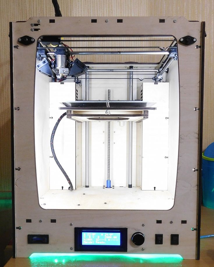 Of course, the torque is greatly decreased and the accuracy may not be perfect, but after slowing down, the motors regain nominal torque and the position is accurate. 900mm/s is the maximum speed that I considered safe before starting to lose steps.
I also tried to use raw data from the oscilloscope to calculate and show the averaged “voltage consumption” during operation. It proved to be a bit harder than I’d anticipated, so the results are only indicative – that’s why there are no numbers presented. Anyway:
The two graphs present voltage and current with “Local RMS”, which is more or less the averaged effective value. We can see that as the speed increases, we need to apply more and more voltage until we reach the limit and at that point the current is falling a bit. Two important conclusions come from these graphs:
- We can never deliver 100% of the supply voltage because we need the current to be changing -> we need some time for it to fall down;
- At high speeds, we are unable to deliver full power to the motor.
Benefits of higher supply voltage
Some of you could have realised that in most of the measurements I was using 32V, not 24V power supply. That’s true – I recently upgraded my machine to 32V and that’s why I decided to play around with my oscilloscope and compare both options.
Was it worth it? Definitely!
With move parameters like previously, the waveform shape looks much better and current amplitude is ~60% higher than before, which means better stability and higher margin before motors start losing steps. On the other hand, instead of a higher safety margin, I can print with quite high accelerations and even reach a speed of 1200mm/s! Not that it makes much sense for a filament printer.. but I’m really happy with the results.
Summary and recommendations
Even a few volts of difference will improve operation of our stepper motor driver or allow us to reach higher speeds. Sometimes higher printing speed will come with decreased print quality, but that’s often not a big issue and at the very least we can increase the travel speed, which will not only reduce print time but is also helpful for retraction tuning.
With all the knowledge we got, now we can choose motors for our machine more confidently. So:
- Keep the motor rated inductance and resistance as low as possible;
- For drivers like TMC2208 or TMC2130, 1.5 – 1.7A rated motor current should be optimal;
- For TMC2209, TMC2660 and TMC51X0, 2.0 – 2.5A rated motors will be OK;
- Choose motor power supply voltage as high as possible, but double-check ratings of your drivers and mainboard!
Personally, I think that in the next few years we will see more and more 36V and later 48V – ready motherboards for Reprap/commercial 3D printers, as our machines keep getting better and could make use of a speed boost. The only downside to it is that heaters are usually designed for 24V – but maybe that will change too! We will see.
Equipment used:
- Siglent SDS 1104X-E Oscilloscope
- Hantek CC65 current probe
- 150W Mean Well power supply
- CoreXY 3D printer
- Custom TMC2208 board
You can learn more about PWM here:
https://en.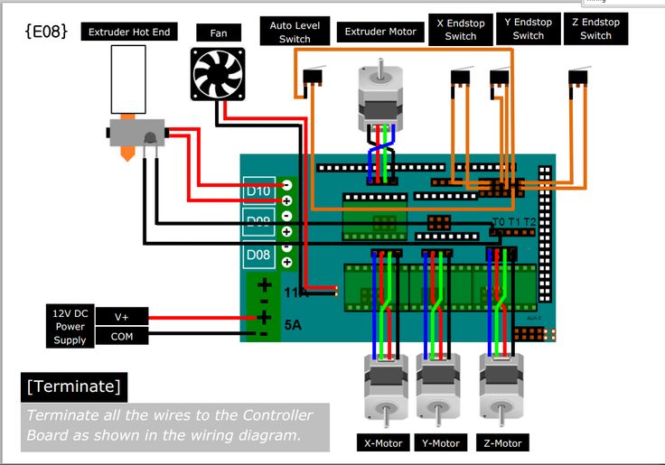 wikipedia.org/wiki/Pulse-width_modulation
July 30, 2021 / Trinamic /
Categories: Guest blog, Products, technology
Tags: 3d printing, guest blog, motor driver, technology, TMC2208
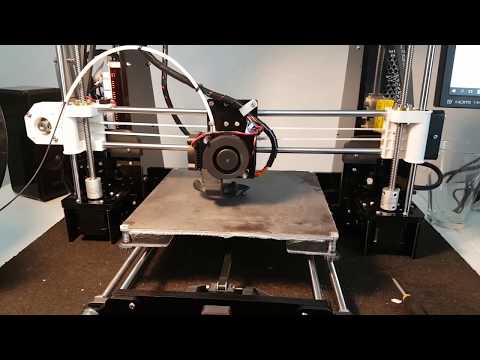
(There is a solution) Y-axis error
I have a used Creality CR-10S and have been using it for a day now. Looks like I'm having trouble with the y-axis. Several times when I chose "Automatic Home", the type bed only moved a fraction of the distance it needed to have to get the head into the bottom left corner. The only problem is the movement of the table; head each time successfully moved to the leftmost position.
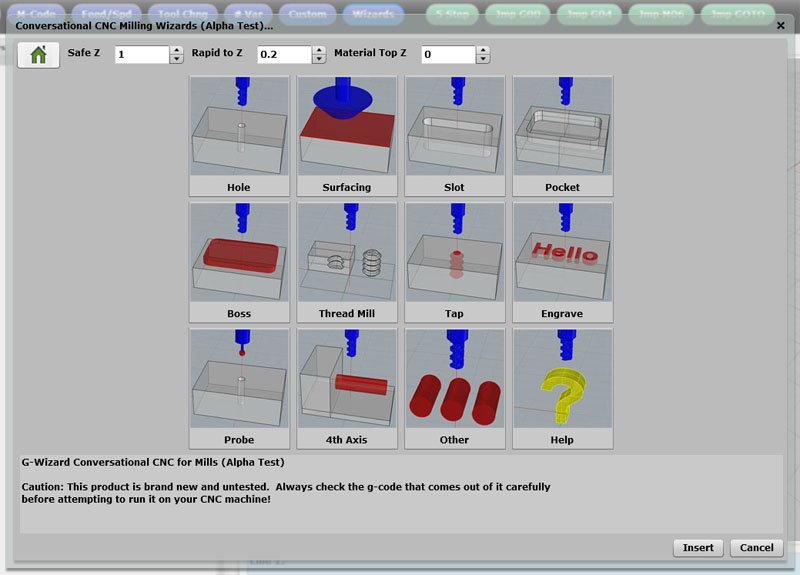
It doesn't always happen, and when it does it usually seems to go half as far as it should, but one day the table didn't budge at all. I have a similar issue with "Automatic Table Leveling". Once, when it was supposed to go to the rear left corner, the nozzle missed the table by about 5 mm. I tried to move it with "Move axis" but it thinks it's at 0.00 and it won't let me go negative. One way to fix this is to "Disable steppers" and then move the table manually. nine0003
I made two prints, and in both cases there was no y-axis offset during printing. After the first print, "Auto home" was only halfway through, but I didn't pay attention to other details. After the second print, the machine was off and I moved the table by hand in response to @octopus8. Then I turned it on and selected "Auto home". The head went down and moved to the left, but the Y-axis didn't move at all.
When I move the table manually through its entire range, either with the machine turned off or after selecting "Disable Steppers", it is quite smooth. It has some movement resistance, about the same as the X-axis resistance. I can feel very small "steps" if I move very slowly. They are both consistent throughout his range. There are no separate places where he behaves differently. nine0003
I made sure the table belt is tight.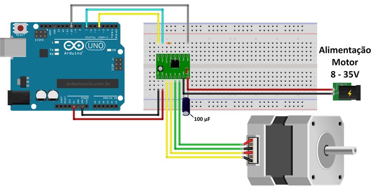 I check the wheels under the table. I wiped them off with a rag. When I turned them by hand, a few slipped onto the rails (not making the table move when I turned the wheel.) I tightened their bolts and it pulled some of them to the rail, but a few others are still sliding on the rail. Is it important? After making these adjustments and turning on the printer, "Auto home" worked, and the steps on "Bed Auto Leveling" also did the right thing. I'll report back more experience after adjusting as I get it. nine0003
Please let me know what tests I can do and what additional information I can provide to help resolve this issue.
▲ 1
octopus8 recommended a series of tests to determine the cause of the problem.
I started by moving the table manually (don't forget to turn off the machine or select "Disable steppers" from the "Prepare" menu) and the movement was relatively smooth with some resistance, the same as moving the X axis. If you are moving very slowly , you may feel light, small "steps", this is normal.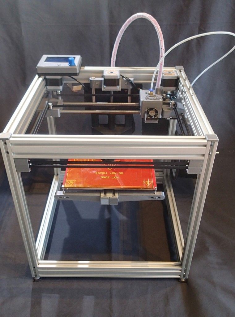 Movement was consistent across the entire range of motion. nine0003
Since this did not indicate a problem, I proceeded to check the drive belt and road wheels. The belt had a slight slack which I tightened. Several wheels under the table slid along the tracks they were running on. I pulled them tight. This improved the movement of a pair of them, but the pair still slipped a bit.
I had no more problems after that. For 10+ prints within a week or so, there was no incorrect Y-axis movement and "Auto home" always worked. However, I continued with the next test proposal, which was to send some simple gcode to the printer via USB. I used both Ultimaker Cura 4.8.0 monitor mode and [sending commands from Linux terminal][1]. I sent commands
G28 G0 FG0 X200 Y0 G0 X200 Y200 G0 X0 Y200 G0 X0 Y0
with values 900,1800,2700,3600 and 4500 for and each time the print head returned to the same place.
This indicates that tightening the belt and wheels probably corrected the problem.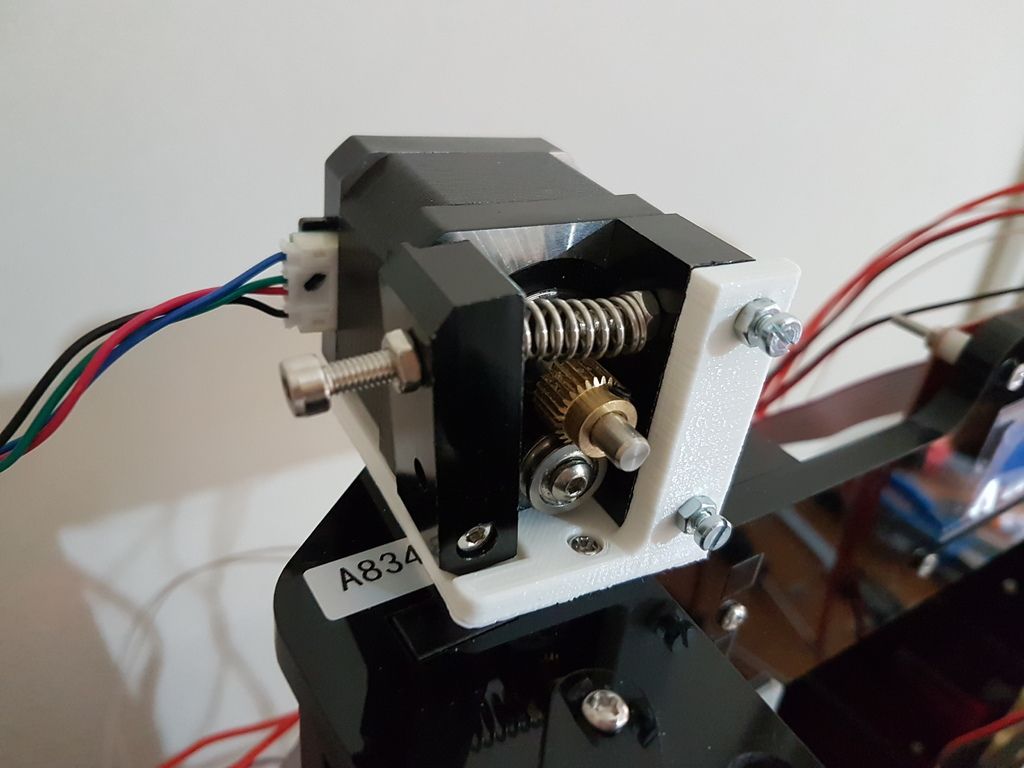 [1]: How to directly send a G-code to a printer from a Linux terminal?
, @ brett stevens
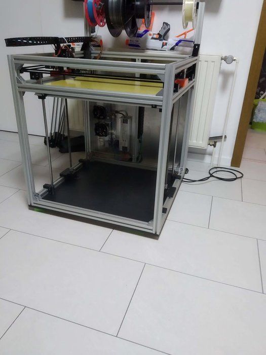
I saw, plan, assemble a 3d printer from junk and sticks / Sudo Null IT News0001
I have long wanted to have a 3d printer. A year and a half - exactly, maybe even more. I even learned how to model a little in DesignSpark Mechanical and occasionally drew all sorts of useful and not very things in it, for example, I redid the buttons on my Logitech G27 steering wheel to make it easier to press with gloves: G27 Button Plates. The flight of fancy in the manufacture of all sorts of different things was limited only by the lack of a printer, because printing somewhere else is long, inconvenient and not too cheap. Only one thing stopped me - I needed money for my printer, and for some reason they are always chronically lacking. After much deliberation, I decided to assemble the printer myself, and, given the above circumstance, to make the most of any rubbish lying around at work. nine0041
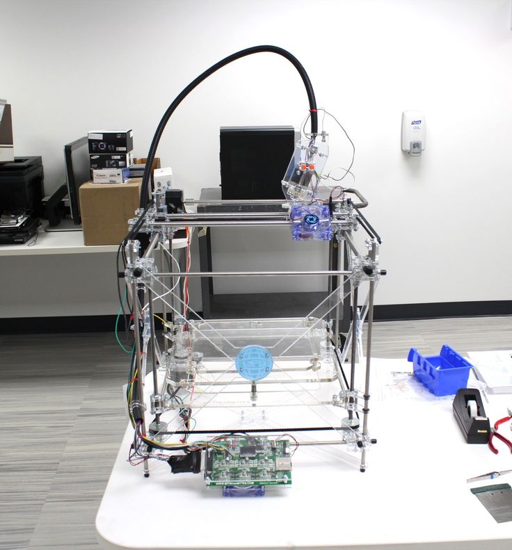
Since before that I had only seen 3D printers from afar and had a very rough idea about them, I began preparations by studying the forums, while the best one I found from Russian speakers on this topic is the section on 3D printing on roboforum.ru (http://roboforum. ru/forum107/). Local elders recommend assembling the first Mendel90 printer from dibond (aluminum composite sheets), by this time I had already begun to assemble Prusa i3 from 12 mm plywood. Looking ahead, I’ll say that this is not the best choice, it was necessary either to order a ready-made aluminum frame, or to do all the same Mendel90, it is much more rigid, which will increase print speed and reduce noise and vibration.
The first step I tried to imagine what exactly I will collect. DS Mechanical was fine for a quick first sketch:
A sample shopping list originally looked like this:
- 3D Printer Controller RAMPS 1.4 + Mega 2560 R3 + 5pcs A4988 For Arduino RepRap + 3 endstops goo.
 gl/trkdsM $ 40.00
 - 12V 24V 3D Printer Heatbed MK2B RepRap PCB Hot Plate Heat Bed For Prusa & Mendel goo.gl/4nS4ry $ 12.00
- (2)8mm Bearing CNC Aluminum Rail Linear Motion Shaft Support Series Slide SK-8 goo.gl/Dzwxtr $ 4.00
- 12v Extruder for 3D Printer goo.gl/rOonr5 $ 60.00
- SC8UU SCS8UU 8mm Linear Motion Ball Bearing Slide Bushing Linear Shaft — 4 pcs goo.gl/T36aYa $ 13.00
- 8x400mm Outer Diameter Shaft Optical Axis Cylinder Linear Rail Series - 1 goo.gl/XlLMtN $ 5.00
- 2 Meters Of GT2 Belt goo.gl/M2q7VH $7.00 nine0051 GT2 20 tooth Timing Pulley - 2 pcs goo.gl/M2q7VH $ 4.00
- 20T 5mm Bore 6mm GT2 Timing belt Idler Pulley 1 pcs goo.gl/gtNVeE $ 10.00
- 4pcs NEMA 17 1.8° 2.6 kg.cm flat shaft Stepper Motor goo.gl/8KBxcg $ 60.00
- Mounting Bracket for 42mm NEMA17 stepper motor 3 pcs goo.gl/G2eg7A $ 18.00
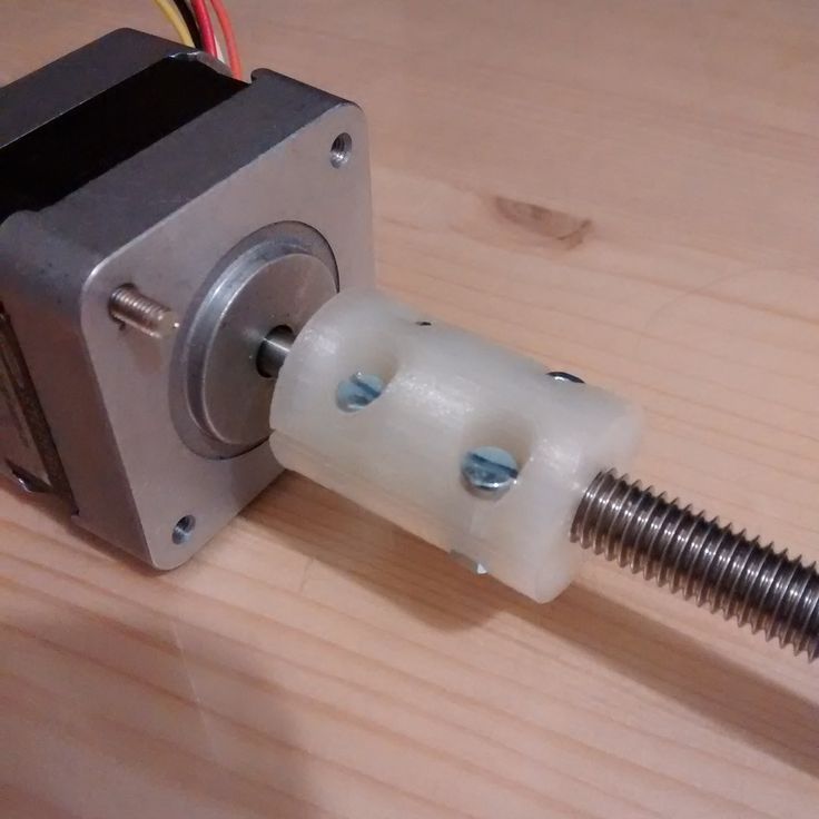
- 2pcs Coupler 5 x 8 mm for 3D Printer Z Axis NEMA17 Stepper Motor RepRap goo.
 gl/PJkouI $ 4.00
 - 10pcs Spring for 3D Printer Extruder Heated Bed For Ultimaker Makerbot $ 2.00
- 2 Pcs 8mm Zinc Alloy Pillow Block Bore Inner Diameter Metal Ball Bearing goo.gl/tUYyZp $ 6.50
Printed parts were not supposed to be used at all, steppers should be hung on metal corners, vertical feed - on M8 construction studs, frame and table - from 12 mm plywood, guides - 8 mm with SC8UU plain bearings, clamp them into brackets SK-8 (all searched on eBay by name). I made a preliminary list of parts and started looking on ebay for what you can buy at auctions cheaper. While choosing where to buy cheaper - I drew a sheet of plywood:
Sawed by hand, no laser cutting, only electric jigsaw, only hardcore!
While I was processing pieces of wood, I was picking up an old scanner at work, a couple of matrix printers, a card embosser, I managed to get hold of one long 8 mm shaft, two short 10 mm, a steep aluminum rail along which a steel plate with holes rode on wheels.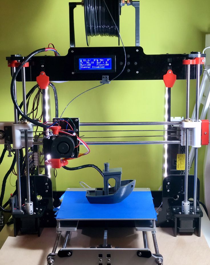 From there, I broke out the fastenings of the print head of the matrix, they had bronze plain bearings. As a result, already at the frame assembly stage, small changes were made to the project and the frame already differed from the first picture:
One of the 8 mm shafts still had to be ordered, the hope of finding suitable steppers in the printers did not materialize, NEMA 17 still comes across in the matrix, but with insufficient torque and a tightly mounted gear, which I could not remove. Since I ditched the 8mm x guides in favor of the embosser rail, I drastically reduced the number of SC8UU bearings needed, in the final version, three were enough. By the way, the bearings are shit, when I put them on the shaft - balls flew from one to the floor, they slide badly too, they have no lubrication at all from the factory. I ordered extended LM8LUU to replace, I'll see how they behave. In general, the people of the carriage and on rolling bearings collect, they say that it turns out much better.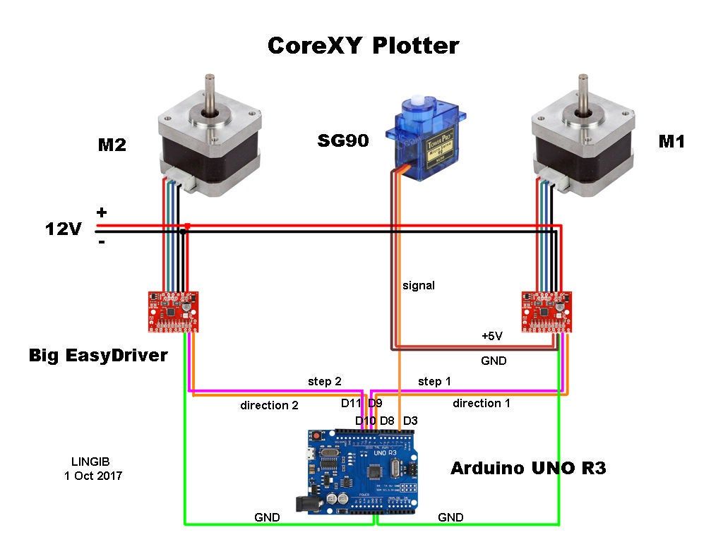 nine0003
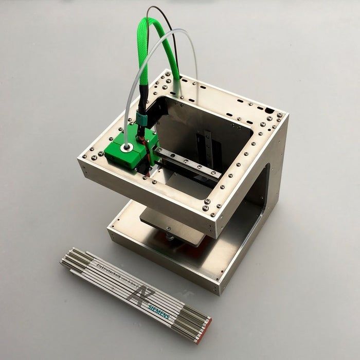
The plywood frame is not too rigid, so I decided to use a Bowden extruder to increase the print accuracy. The lighter the head, the less the frame will swing during acceleration, the higher the print accuracy. I managed to find a small and light hot end, with a very successful fastening at the bottom with a copper plate, and not with a clamp at the top, like most:
frames. In general, it is better to immediately assemble a reinforced version of the frame, such as this one:
Separately, I want to mention the plywood hot table - never do that! I was tormented to put it evenly, 12 mm plywood easily bends when tightening the fastening of the heating element, on the third attempt I managed to achieve relief fluctuations on the printed surface within 1 mm over the entire area, but it was not easy. It’s better to take a ready-made aluminum one, on eBay in the region of $ 30, but how much nerves you will save is beyond words.
The second interesting point is that the parts from the children's iron constructor were very useful, while the printer itself cannot print yet - a lot can be assembled from it. Here, for example, the belt roller along the Y axis:
Another way to save money is the power supply. The savings, however, are so-so, the power supply for LED strips for 12 volts 30 amps on eBay costs not at all space $ 30. I decided to go my own way again and used a 500W power supply from an HP Proliant server, which delivers the same 30 amps on the 12 volt line, but at the same time it makes quite a noticeable noise. The power is enough, but I'd rather change it to something quieter.
I decided to use the cheapest electronics - RAMPS 1.4 + Mega R3, however, I took more powerful drivers - DRV8825. Radiators were included with them, they were of little use, they warmed up so that it hurt to hold your hand, I hung a 60 mm fan with a diameter of 0.2 A opposite, now they almost do not heat up even without radiators. By the way, I am very surprised that many people advise using microstepping 1/16, I even had skipped steps at 1/8, everything was fine at 1/4. The direct drive extruder works without microstepping at all, it is noisy, but there are no feed problems. Carefully insert drivers into RAMPS !!! Insert it upside down or with an offset - the arduina will rise beautifully and go to the trash, I have both chips burned out :(((
As a result, after a couple of months of finishing with a hacksaw, jigsaw, needle files, soldering and twisting, the printer looked like this:
I am printing a raft…
There were no problems with the mechanics right away, a box with a thickness of 1 layer 0.2 mm was printed immediately evenly and with the correct dimensions, except that the upper layers settled due to lack of cooling. True, I almost immediately replaced the roller from the designer with a normal bearing with a self-printed mount:
Did I manage to save money? Yes, probably 30 percent of the cost of the Chinese Prusa i3 kit with shipping. Everything works, I print with a layer of 0.2 with good quality, there is a slight wobble along the Z axis, I think it will be possible to remove it by changing the fastening of the studs, perhaps by switching to thinner studs.