Solid works 3d printing
How Do I 3D Print from SOLIDWORKS
TriMech Video Tech Tips, 3D CAD, SOLIDWORKS, Tech Tips
By David Cano-Mejia on
As 3D printing becomes more common in the workplace, users are turning to SOLIDWORKS to better understand their designs in the context of 3D printing. SOLIDWORKS offers several 3D printing visualization and analysis tools and all of them can be accessed through the Print3D tool (File > Print3D). Let’s take a look!
Does My Part Fit on My Printer?
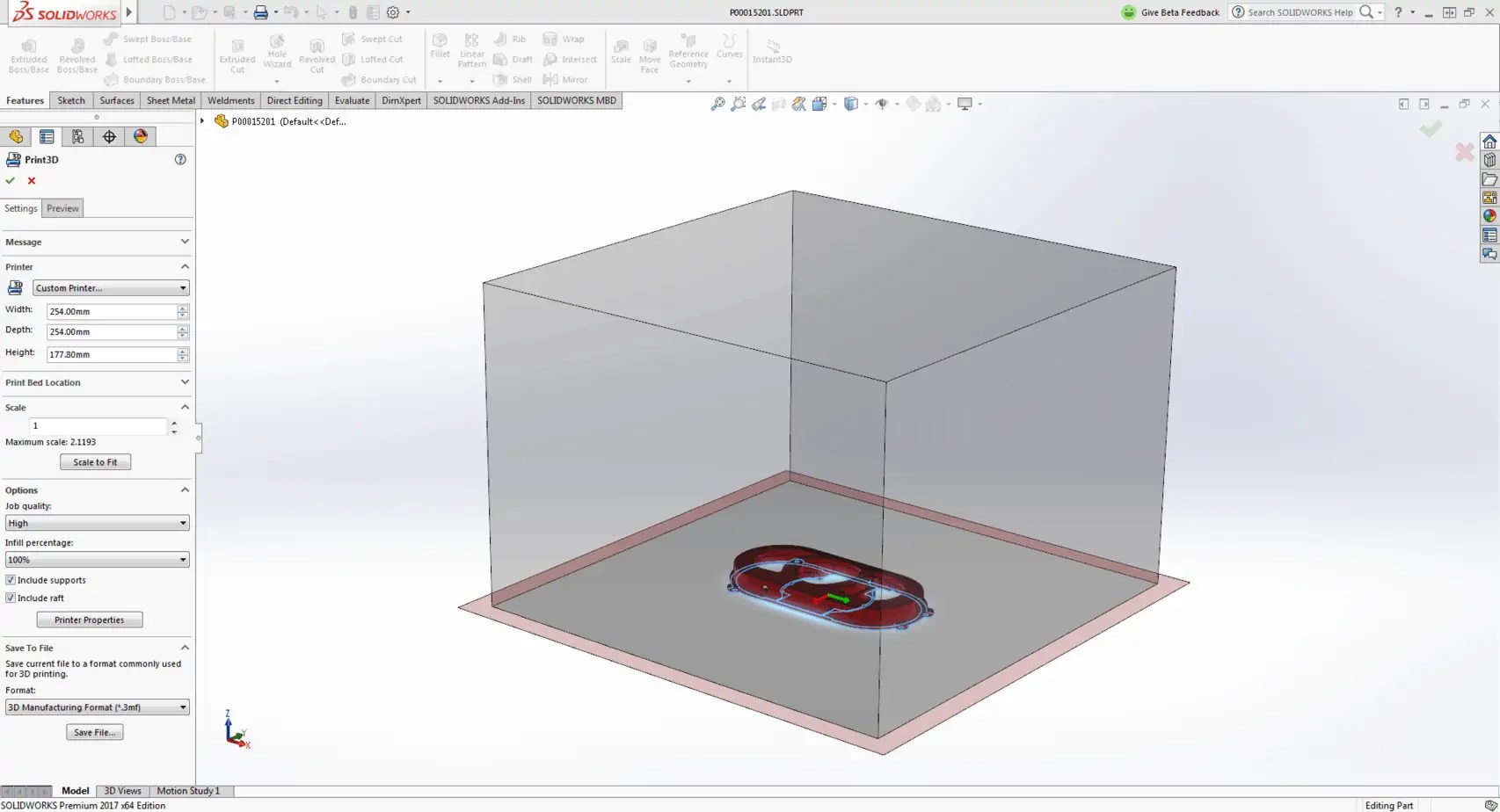
The first step in analyzing your design for 3D printing is to ensure that it will fit inside the print area. Under Printer, you can select the 3D printer that you will be using. If this is your first time using the Print3D command, you will need to add your printers to your favorites list. Click on Manage Favorites to browse all available 3D printers. SOLIDWORKS has added a comprehensive list of 3D printers with up-to-date envelope information so you can quickly find your most used printers and add them to your Favorites for easy access. If for some reason your 3D printer is not listed under this library, you can define a Custom Printer by manually inputting the print volume dimensions.
Under Print Bed Location select a plane, or planar face, to be defined as the bottom plane of the model. This will automatically orient your model on the print bed. If the model is larger than the print volume, the geometry outside the print volume will be highlighted in red and you will not be able to print. If you need to change the orientation of the model, you can use the translation controls, manually type in the desired print bed angle and offsets in the Print3D PropertyManager, or click Orient to Fit to let SOLIDWORKS orient your part or assembly for you.
Under Scale, you can also choose to print your design at a scale other than 1, which is the current size of the model in SOLIDWORKS. To do so, type a value for the scale factor. The new value is saved as a document property in the SOLIDWORKS file so if you print the model again, the saved value is used still there. The Scale to Fit option sets the scale to the largest value that will still fit inside of the print volume.
Can I Analyze My 3d Print?
Sure! You just have to switch over to the Preview tab in the Print3D PropertyManager. There are several analysis tools that you can use to get a better understanding of the design to be printed.
- Build Analysis
- This allows you to preview the faces of your model that may require supports. Depending on the printer being used, at a certain overhang angle, the print quality is greatly affected unless supports are used. Type in the maximum angle for the faces that will require support.
 I recommend changing the Support face color to red and checking Show As Transparent to make it easy to visualize all of the faces that will need support.
- This allows you to preview the faces of your model that may require supports. Depending on the printer being used, at a certain overhang angle, the print quality is greatly affected unless supports are used. Type in the maximum angle for the faces that will require support.
- Layer Height
- This option lets you visualize the height of each print layer in order to determine whether the print resolution is sufficiently fine to produce the desired print. Type in a layer height and turn on Show Striation Lines in order to get a preview.
- If you are planning on exporting your file as a .3MF (3D Manufacturing Format), you can choose to let SOLIDWORKS generate the slices for the 3D print and embed those into the .3MF file instead of slicing the model using the printer’s slicer software
- Thickness/Gap Analysis
- If you are using FDM (Fused Deposition Modeling) for your prints, this calculates the ideal wall thickness/gap based on the material that you set and the layer height.
How Do I Export the File to Be 3D Printed?
When you are done analyzing and visualizing your design, you are ready to export the 3D print files. You can export part and assembly files to STL (.stl), 3D Manufacturing Format (.3mf), or Additive Manufacturing File Format (.amf) files.
- STL (*.stl)
- This ASCII or binary format file describes only the surface geometry of a 3D object as a raw, unstructured triangulated surface.
- 3D Manufacturing Format (*.3mf)
- This is a 3D focused file format that contains 3D model, material, and property information for sharing full-fidelity 3D models to other applications, platforms, services, and printers.
- Additive Manufacturing File (*.amf)
- This xml-based file lets you select export options that store the color, scale and materials of the object to be 3D printed in the .AMF file, as well as the geometry of the model.
Under Save To File, select your desired format and click Save File. Once you have one of these files, you can import it into your printer’s slicer software to generate the G-code that the printer will use to print your design.
Can I Print Directly From SOLIDWORKS?
Yes, but only if your 3D printer manufacturer uses the SOLIDWORKS 3D Print API. As soon as you finish using the Print3D command and click OK , the 3D printing rapid prototyping dialog box will open to ensure that your printer’s build area is empty. The printer will start to warm up get ready to print. If your 3D printer does not use the SOLIDWORKS 3D Print API, you can still export the file as described above and import it into your printer’s slicer software.
How Do I Set My 3D Printing Options?
If you are planning on printing directly from SOLIDWORKS, you can set the 3D printing options that you would typically set in the slicer software. Job Quality corresponds to the print layer height and is the printer’s approximation to match that resolution. Infill Percentage lets you select the percentage of the part that is solid. You can select between 0%, 10%, 40%, 70%, and 100%.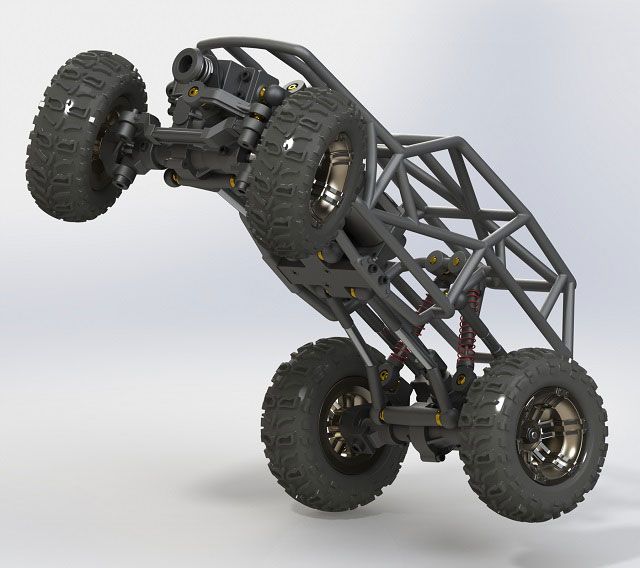 Infill percentage can greatly affect print times and part strength. Include Raft builds the print output on top of a raft of disposable material that you can remove after printing. This option is cleared by default. Include Supports adds supports for model faces that are in open space with no part of the model supporting the face. This option is selected by default and resets to the default each time that you open the Print3D PropertyManager.
The tools available inside of the Print3D command are easy to use and set up. Even if a different slicer software ends up being used to send the model to the printer, these tools can serve as a great starting point to understand the 3D printing requirements that your specific design may have.
Ready to learn more about SOLIDWORKS? Explore the different training options that we have to offer.
Should you use SOLIDWORKS for 3D printing?
Published on May 7, 2020 by Carlota V.
In industrial sectors and product design, SOLIDWORKS is a CAD solution many rely on. The software has been around since the mid 90s and the latest figures estimate that there are around 9.3 million active users across 80 countries. It is based on parametric modeling and is primarily used to create 3D models and assemblies. SOLIDWORKS has also been adopted in the world of additive manufacturing as it enables engineers to save their models in a STL format; the format needed for a 3D model to be processed by 3D printing software.
SOLIDWORKS was developed back in 1993 when John Hirschtick, a member of the MIT Blackjack Team, recruited a team of engineers to create the first accessible and affordable 3D modeling solution. At the time, AutoCAD, which had been released in 1989, was limited to the creation and editing of 2D geometry. Therefore, SOLIDWORKS was the first software to bring an accessible 3D modeling solution to the market. For many engineers, 3D modeling truly changed the way they could bring creations to life.
One of the first versions of the software
Soon enough the software became extremely popular and Dassault Systèmes decided to acquire it in 1997 for $320 million in stock. At the time, Dassault Systèmes was known for its CATIA solution, a product lifecycle management suite, which combines design, engineering, and manufacturing features used for automotive, aerospace and aeronautics. Essentially, SOLIDWORKS is a lighter version of CATIA.
Main Features of SOLIDWORKS
As mentioned, SOLIDWORKS is a CAD software based on parametric design. Parametric design is a process that clarifies the relationship between design intent and design response. One of the key features of parametric models is that attributes that are interlinked can automatically change their feature when one attribute is changed. This modeling process is great for projects with a lot of manufacturing requirements. 3D models can be created for high performance parts and assemblies used in sectors such as aerospace & defence or automotive.
For example, the very popular AutoCAD solution from Autodesk is primarily a 2D CAD software that caters to architects, home builders and civil engineers. Even though it is possible to create basic 3D surface and solid modeling with AutoCAD, it is not its key feature, and definitely not as easy as working on a parametric modeling software. This is the key benefit of SOLIDWORKS.
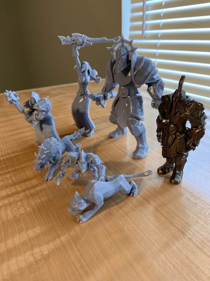
It is primarily used to model parts or assemblies (as is the case here)
Furthermore, SOLIDWORKS also includes very beneficial features for a number of industrial applications such as simulation, rendering tools and CAM (computer-aided manufacturing) tools. You will be able to create solid models with SOLIDWORKS, but also import, create, and manipulate surfaces, view models in wireframe mode, and generate 2D drawings from the 3D solid models.
SOLIDWORKS Standard
SOLIDWORKS Standard will enable engineers and designers to create parametric parts, assemblies, production level drawings, as well as generating complex surfaces, sheet metal flat patterns, and structural weldments. Thanks to its parametric design feature, the models will automatically update with design changes. Conceptual design is also an important capability of the software as it allows to create layout stretches, apply motors and forces to check mechanism performance, etc. The Standard license costs $3,995 with an annual maintenance fee of $1,295.
SOLIDWORKS Professional
SOLIDWORKS Professional builds on the capabilities of SOLIDWORKS Standard to increase design productivity, with file management tools, advanced photo-realistic rendering, automated cost-elimination, design checking and a parts library. The Professional licence costs $5,490 with an annual maintenance fee of $1,495.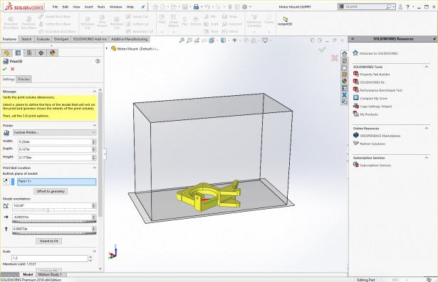
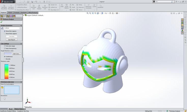
It can offer powerful simulation tools
SOLIDWORKS Premium
SOLIDWORKS Premium adds powerful simulation and design validation to the capabilities of SOLIDWORKS Professional, plus reverse engineering, and advanced wire and pipe routing functionality. ScanTo3D tools, available in SOLIDWORKS Premium, import mesh and point cloud data from which you can create surfaces and solid models. The Premium licence costs $7,995 with an annual maintenance fee of $1,995.
SOLIDWORKS for 3D printing
As mentioned, SOLIDWORKS can be used for additive manufacturing technologies because you can save your 3D model as an STL file. This is the format needed to transform the data from the model into G-code that a 3D printer can work with. However, this is not the only way in which SOLIDWORKS is suited for additive manufacturing projects. When designing for additive manufacturing, there will be many design considerations to take into account. Anything from distortions, warping, and breaking can occur, which means a 3D model must be adjusted accordingly.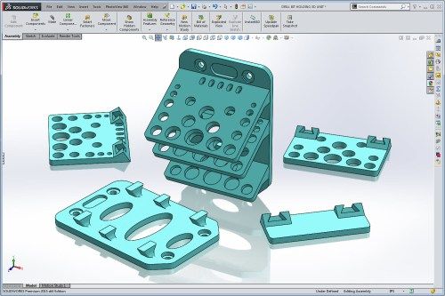
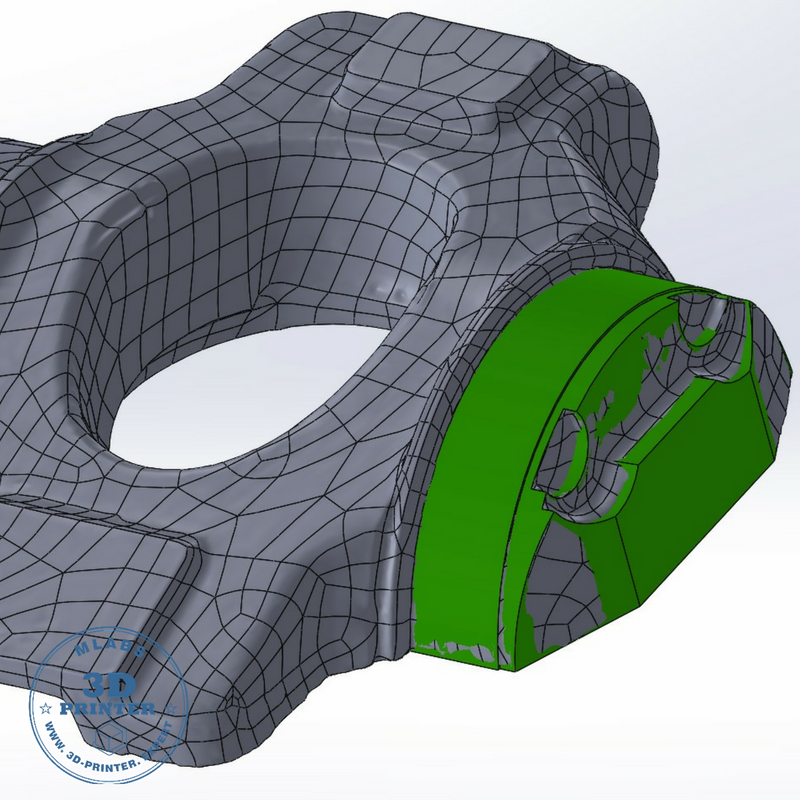
Topology Optimization is one of the design techniques possible on SOLIDWORKS
SOLIDWORKS has put in place tools that account for the special requirements of AM techniques, including support structures, and any distortion that can arise during printing. These features are extremely important, especially when working with expensive materials such as metals, where failed prints can be very costly. Finally, given the design freedom that 3D printing technologies allow, design techniques such as topology optimization can be applied to models. Another way to save material consumption and optimize a part! You can find more information HERE.
Do you use SOLIDWORKS? Let us know in a comment below or on our Facebook and Twitter pages! Sign up for our free weekly Newsletter, all the latest news in 3D printing straight to your inbox!
Preparing a model for 3D printing in SolidWorks
by 3DAdmin · 10/09/2016
In this article, you will learn how to create and prepare a model for subsequent 3D printing in SolidWorks.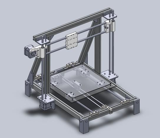
The process of building a three-dimensional model of the part:
- Open the SolidWorks program, create the document “Part”.
- Open the Design Tree, click on the Top View icon.
- Orient this plane perpendicularly in the View Orientation panel.
- On the "Sketch" toolbar, click on the "Rectangle" icon and draw this shape in the sketch.
- With the left mouse button (LMB), click on any free space in the drawing window. The rectangle will turn blue, indicating that no dimensions have been set.
- Click on one of the sides of the rectangle and delete it.
- In place of the remote side, draw an arc using the “Arc through three points” function.
- The next step is to relate the origin to the sketch elements. You can do this by activating "Add Relationship".
- Between the center of the arc and the starting point, we establish the relationship “Coincidence”.
- After that, open the window and set the dimensions of the sketch.

- Click LMB on any point of the figure, and then on any free space outside the drawing. This activates the "Automatic Dimensioning" function.
- Create a solid element.
- Click on the “Extruded Boss” icon, set the extrusion. We activate the function.
- Create a cylinder.
- Activate the top face of the base with LMB.
- Click on the “Create Sketch” icon and call the “Perpendicular” function.
- Activate the “Circle” icon.
- Move the cursor to the starting point and click LMB. Move the cursor away from the center and press the button again to designate the second point.
- Set the circle size on the SolidWorks toolbar. Activate the "Automatic dimensioning" function.
- Click on the “Extruded Boss” icon and extrude the circle by 30 mm.
- Building a square cutout.
- Activate the top face of the base. Click on the “Create Sketch” icon and orient it perpendicularly.
- Click on the “Rectangle” icon, draw a square and enter its dimensions from the edges of the part.
- Activate the "Extruded cut" function, enter a value of 20 mm.
- Click on the “Slope” icon, enter the parameters. “Tilt angle” - 15 mm, “Neutral plane” - the bottom of the square cutout.
- In the “Slope faces” window, double-clicking the LMB, we write the side faces of the square cutout.
- Click on the “Rounding” icon, enter the value of the rounding radius -10 mm.
- Create a cutout. Orient the sketch plane perpendicularly.
- Select the "Polygon" icon. Click LMB on the place where the polygon will be located. Click again with LMB and specify the position of one of the vertices.
- Activate "Add Relationship". Click LMB on one of the edges of the polygon and set the relationship “Vertical”.
- Enter the edge size - 10 mm.
- Set the size of the position of the center of the figure.
- We establish a relationship between the starting point and the center of the polygon.
- Activate the "Extruded cut" and set the value to 150 mm (inside the part).
And so, we have created a 3D model. And now the most important part - preparing the model for 3D printing.
- In order to be able to print a 3D model, it must be “water tightness” (i.e. solid, forming a closed volume). If blue surfaces are visible on the model, then more layers should be added so that this color is not visible. Each edge should have no more and no less than two layers, if this is not the case, then the extra surfaces should be removed. The most common errors when modeling in SolidWorks:
- Internal surfaces
- Holes
- Keep in mind that if your model consists of several objects (for example, letters), they must be combined into one object using a slicer.
- It is desirable that the base of the model be flat. If it is not so, delamination may occur, as a result of which the coordinate axes may shift. If it is not possible to make the base flat, the model should be printed on a raft.

- If your model has a lot of overhanging structures, make a support for each. In order to successfully print the model, the angle of inclination of the walls should be no more than 45 degrees.
- If the model has many small parts, they must be larger than the nozzle diameter. Otherwise, the 3D printer will not be able to print them.
- If your model is large, it is better to print it in parts. To do this, it should be cut, and then connected with glue. However, it will be better if you immediately foresee this and make secret connections.
- You should also think about the strength of the model. It is better that the load is distributed across the layers. But if you make it across, the model will quickly unstick.
- It remains to decide on the file format. The most popular and convenient is STL. It is with him that most slicers work, including Repeater-Host and Cura.
Thus, we have learned how to create parts in the SolidWorks application and prepare them for subsequent printing on a domestic or industrial FDM 3D printer. Now try to apply the acquired knowledge and create your own unique model.
Did you like it? Show your friends!
You will like it
3d modeling in SolidWorks | Planet3DRu
11/27/2021
In this tutorial, you will learn how to create motion in assemblies based on the physical properties of various materials, and also analyze the results of the interaction of various elements of an assembly with each other using SOLIDWORKS Motion (more…)
10/29/2021
You will learn how to create a thread in SolidWorks in several ways, these are really simple and convenient ways. (more…)
06/19/2021
If you don't know how to make a drawing from a sketch or an assembly in SolidWorks to make a part according to the drawings, then in this lesson a detailed explanation (more...)
03/13/2021
In this SolidWorks lesson, you will learn how to split a large part into several smaller ones if, for example, the part is not within the printable area of a 3D printer. (more…)
03.03.2021
In this article, you will learn about ten rules of good form when modeling products in SolidWorks. (more…)
01/25/2021
In this lesson, you can learn how to create threads in various ways (more…)
07/09/2020
In this SolidWorks video tutorial you will learn how to create a 3D model using a photo as a reference. (more…)
05/11/2020
Lesson 9: Creating assembly drawings and product specifications (more…)
04/30/2020
This is the eighth lesson of the SolidWorks Foundation Course. This time we will talk about creating part drawings. (more…)
04/29/2020
The seventh lesson from the basic course SolidWorks. (more…)
04/29/2020
The sixth lesson from the basic SolidWorks course, in which I will show you how to create assemblies. (more…)
04/29/2020
The fifth lesson in the SolidWorks Core Course, in which we continue our introduction to the basics of part modeling.