3D printed engine block metal
Creating Pistons and Engine Block
GM’s LS3 Engine is part of the company’s vast family of small-block V8’s. It was used in the Corvette for 5 years (from 2008 to 2013) and in the Camaro SS for another 5 years (from 2010 to 2015). The LS3 is an updated version of the LS2 casting, but with bigger bores and a 10.7:1 compression ratio. the camshaft is a more aggressive 0.551″ lift, and the overall displacement is over 6.1L.
Traditional small-block V8’s have a certain sonic characteristic to them that sounds guttural and off-balance. The sound is raw and distinct, as the pistons fire at offset intervals, which rattles the block a lot more.
I’ve always wanted a V8 engine, but rather than spending over $7000 for one, I figured I’d 3D print one. The project was exciting, time consuming, but in the end, totally worth it. These next few blogs will be a part-by-part account of the entire project from start to finish. At the end of each part, I’ll include a “Tips n’ Tricks” section where I cover some important bits of information pertaining to the topics discussed in the segment.
Let’s get started.
The 3D Models
I think of myself as “pretty proficient” at 3D modelling and designing. However, I knew that modelling an engine assembly from scratch was going to take an unreasonable amount of time. I searched online and found what could arguably be the best 3D model of an LS3 engine I’ve seen to date. Eric Harrell (AKA “ericthepoolboy“) has working models of a Chevy LS3, a Subaru EJ20, a Ford flat head V8, and a Toyota 22RE 4-cylinder engine. You can find all of his designs on Thingiverse.
3D Printed LS3 Engine, courtesy of Eric Harrell.
Eric’s design files include the block, cylinders, headers, valve covers, crankshaft and camshaft assemblies, as well as rocker arms and valves. The parts are extremely detailed have been designed for easy fastening, with pre-cut holes and bores for M3-sized screws. The entire engine – once assembled – moves freely, with integrated bearing sockets for the crankshaft and camshaft. A DC motor is attached to a mounting point that connects the motor to the flywheel, meaning the entire thing will run on its own once powered.![]()
Looking at his final design a little closer, I noticed he was powering the DC motor directly from the wall, so the pistons were “firing” at the same speed. I wanted to demonstrate something a little more dynamic, so I planned out a design for a gas pedal (which I will discuss in a later post). The pedal would act as a potentiometer that would regulate the speed of the pistons.
Once the 3D models were all downloaded, it was time to get printing.
The Print Jobs
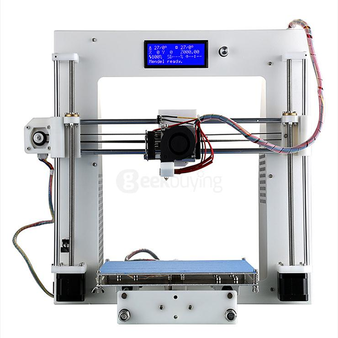
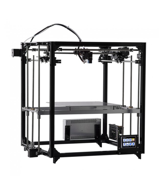
Printing all of these parts was a lot of fun. I had three printers at my disposal, the Fortus 450mc, the 250mc, and the Stratasys F170, part of the Stratasys F123 Series. These three printers, though different in both age and capability, extruded the parts in incredible detail with no hiccups or setbacks. I didn’t have a pre-determined plan on which printer would print which parts, so I organised a print schedule based on what colour options I had access to. I had more colour choices for the 250mc (such as orange, yellow, and grey), so I used it a lot more than I did the F170 and 450mc. I tried to stick with a double-density sparse infill for most of the parts, as it was good balance between material efficiency and part strength. This wasn’t the case for all parts, as they varied in size and complexity (I explain a little more about this in the Tips n’ Tricks section at the end).
The pistons, piston rods, and camshaft were the first things that were printed.
Pistons, piston rods, and camshaft assembly all printed on one build sheet.
Using the “Optimize” feature on the Arrangement tool, the parts were positioned in a way that made it easier for the printer to extrude the material. This optimisation was implemented with every printed cluster of parts.
The full printed piston assembly.
Next was the engine block. This was the longest print out of all of the parts. The block was done on the 250MC and took almost 4 days to finish (not including time for washing and drying). I wanted to print the block in orange (harking back to classic orange Chevy V8 engines), and the only orange material I had was for the 250.
Printing and washing the engine block took almost 6 days to complete.
Most of the other large components were printed in black to compliment the orange block. These parts included the headers, intake manifold, cylinder heads, crankshaft, and flywheel. A few bracket parts like the valley plate and covers were printed in grey to accent the black and orange.
Smaller parts, such as the crankshaft assembly seen below, needed to be printed at a lower layer thickness in order to maintain part detail and fastening features. This was especially important for gears, as the gear teeth needed to be detailed enough for them to sink in and align properly.
The crankshaft assembly was printed on the F170 at a thickness of .070″.
Tips n’ Tricks
It’s a good idea to understand the relationship between layer thickness, detail, and overall part strength. There’s a fine balance between these three aspects of a print job that determines how your part will emerge once printed. For big parts such as my engine block, intake manifold, and cylinder heads, using .10″ layers is ideal. The parts come out stronger, but because they don’t have many finite elements, the detail is still high. Smaller parts such as gears, spacers, pins, bumpers, and rails should be printed in .070″ layers to maintain part accuracy and detail. The parts do come out a little weaker, but you can work around that by printing them solid. The only drawback to this is that the print time will be significantly longer.
Choosing the right layer thickness is determined purely on a case-by-case basis, and is still entirely up to you.
Subscribe for Part 2
This concludes part 1 of my project blog. Subscribe now to receive more parts of my 3D Printing a Small-Block V8 Engine story.
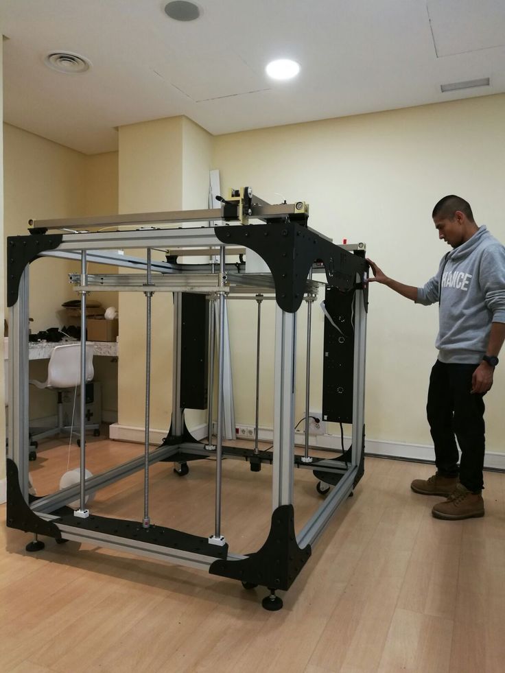
Massive 3D Printer Could Build Engine Blocks
If you could create an engine without restrictions, what would it look like?
Charles Murray | Apr 20, 2018
Watch This Webinar
A gigantic new metal additive manufacturing system at Roush Industries may finally give engineers a glimpse of 3D printing’s ultimate potential in the auto industry.
The new system, an X Line 2000R 3D printer from Concept Laser GmbH, could enable automakers to build radical new test versions of engines, transmissions, and other large components that could previously only have been built by conventional means. By doing so, it could allow OEM engineers and suppliers to consider concepts that they couldn’t previously. “Now they can ask, ‘If we threw out all the rules, does this engine block need to look this way?’” noted Brandi Badami, business development manager for Roush Industries. “’Does it need to be manufactured this way? If we wanted to build the best engine we could without restrictions, what would it look like?’”
The X Line 2000R has a build-envelope of 32” x 16” x 20.” (Image source: Concept Laser GmbH) |
The X Line permits engineers to think in such ways because its build-envelope (32” x 16” x 20”) is unlike anything that has preceded it in metal additive manufacturing. Measuring approximately 17 feet long, the machine is so big that it couldn’t be transported by air; Roush instead had it shipped from Germany to the US by boat. The machine includes two staircases, work platforms, a cooling system, and a material handling system.
As a result of its size, it allows automotive engineers to create 3D-printed engine blocks and large transmission parts, as well as suspension components, chassis components, driveline components, and heat exchangers. It also enables them to redesign multi-part assemblies – integrating them into large single-piece components. Roush Industries, a service bureau that does design and manufacturing work for the auto industry, has already used the machine to incorporate a specialized cylinder head onto an engine block. Badami said the company has more such projects in the works.
“A lot of companies have been embracing additive manufacturing in the last few years, but they’ve been restricted by the size of the build envelope,” she told us. “Now they can consider the components they couldn’t before.”
Badami said the initial, obvious application for the machine is in test. “You can print an engine block and test it before you spend all your time with casting tooling,” she told Design News. “In conventional manufacturing, if there’s an engineering change, it’s expensive and time-consuming to change casting tooling. Here, you can work out the product development up front, before committing all the time and money to tooling.”
In the process, engineers are able to try new ideas, she added. Complex geometries, such as corkscrews, baffles, and tight channels, could be added to an engine block as a test.
To date, the X Line machine has been employed for the creation of aluminum parts using an AlSi10Mg aluminum alloy. Parts produced with the system reportedly exceed or are equal to conventionally manufactured aluminum parts—both in terms of mechanical properties and dimensional tolerances.
Badami said that automotive OEMs have been anxious to employ such ideas for several years, but have been deterred—not only by the small build envelopes, but by the low-volume nature of 3D printing.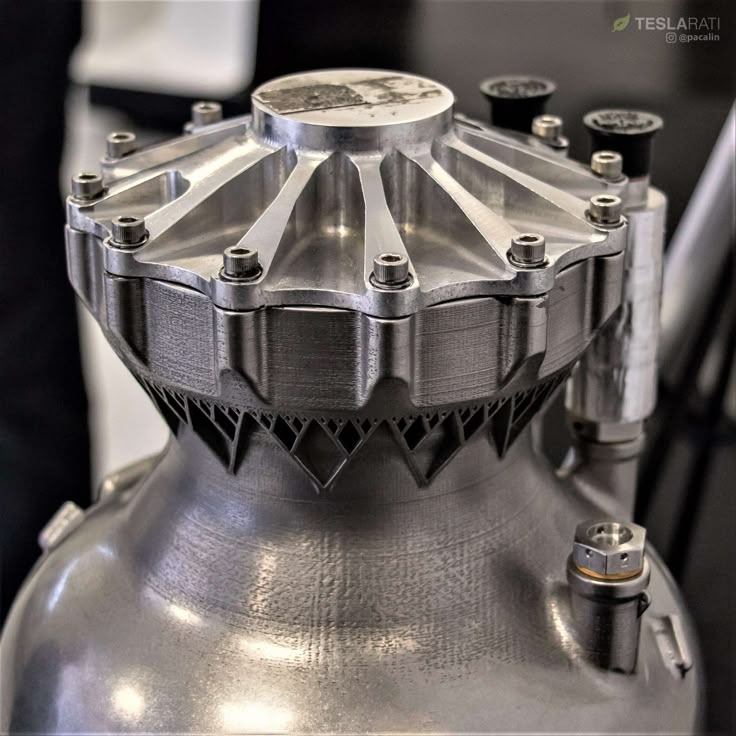 “Medical and aerospace have perfect (production) volumes for additive manufacturing,” she said. “But in automotive, you have millions of parts, so a lot of engineers haven’t considered it. Now, though, the machines are getting bigger and faster, so automotive has the opportunity to catch up and use this technology.”
Roush Industries, a sister division to Roush Performance, knows the auto industry well. It provides expertise in design, engineering, test, assembly, machining, inspection, and manufacturing to automotive, as well as to the aerospace, consumer, energy, and entertainment industries. The company also has 15 years of experience with 3D printing.
Initial expectations for the new 3D printing system in automotive are mainly for test and low-volume applications, Badami said. But that could change over time. “When people start trusting the technology and the materials, and start thinking more in terms of additive manufacturing, we’ll see more complex engineering programs,” she told us.
Read More Articles on Automotive Technology
12 Future Electric Crossovers to Watch
Innoviz Designed a Lidar to Make Any Car Autonomous
Are Small Displacement Turbo Engines Reliable in the Long Term?
Top 10 Most Reliable Car Models for 2018
Senior technical editor Chuck Murray has been writing about technology for 34 years. He joined Design News in 1987, and has covered electronics, automation, fluid power, and auto.
Today's Insights. Tomorrow's Technologies. ESCreturns to Boston, April 18-19, 2018, with a fresh, in-depth, two-day educational program designed specifically for the needs of today's embedded systems professionals. With four comprehensive tracks, new technical tutorials, and a host of top engineering talent on stage, you'll get the specialized training you need to create competitive embedded products. Use the Code DESIGNNEWS to save 20% when you register today! |
 Get hands-on in the classroom and speak directly to the engineers and developers who can help you work faster, cheaper, and smarter.
TAGS: Automotive Engineering
Small firm that started the 3D printing revolution in space
3D printing continues to make its way into the rocket industry. For example, SpaceX used a 3D printed part of the main oxidizer valve back in 2014. And Blue Origin uses 3D printed components in its powerful BE-4 engine.
But one of the organizations with the most experience with 3D printed parts is Rocket Lab based in New Zealand and the US. Founded in 2006 by Peter Beck, Rocket Lab is today the leader in small satellite launches with its Electron rocket. So far, there have been successful launches of six of these rockets – each powered by nine Rutherford engines, built primarily from 3D printed metal parts. In addition, there are a number of other elements obtained using 3D printing technology on board these rockets.
In the traditional subtractive manufacturing approach, the final products are cut from a block of material. 3D printing technology, known as additive manufacturing, allows you to create the desired shape of the part layer by layer. This makes it possible to obtain lighter objects with a complex internal structure that cannot be created in any other way.
Today, Beck, who became President and Chief Engineer of Rocket Lab, discusses with us the company's decision to make significant investments in 3D printing technology and how this technology is being used in the rocket industry today.
How do you see the role of 3D printing in the development of rocket science from the moment you decided to use it to create your engines?
When we started using metal 3d printing, we were among the first to use this technology. I remember when we first announced the Rutherford engine at the National Space Symposium four years ago, everyone looked at it and said, "this is very strange. " But today, if at least part of your engine was not created on a 3d printer, then you are considered behind the times.
We have sent over 50 Rutherford engines into space - that's more 3D printed engines than anyone in history has done. You can do it once, but succeeding 50 times in a row is another level of process understanding and quality control required.
Can you use off-the-shelf commercial equipment or did you have to build your own?
We first bought ready-made 3d printers and improved them. We have modified them to meet our requirements. We print parts in such a shape that even today most industries using 3d printers will tell you that such geometry cannot be printed. Even today, a large number of our components go beyond the conventional boundaries of what is possible.
Have there been any fundamental changes in the design of rockets that you were able to implement only through the use of additive manufacturing?
Of course. I mean, the Rutherford rocket engine, at least as far as we know, is the most successful liquid oxygen and kerosene engine in America, and it performs better than SpaceX's Merlin 1D engine. This is partly due to 3d printing. We 3D print all injectors and we can 3D print the injector geometry that gives us the best mixing and best performance. This cannot be achieved using other manufacturing processes. It's really hard to get a small engine with really big efficiency.
Do you think that 3d printing offers any advantages specific to rocket science?
Yes, of course. The same can be said about any industry. When very complex components are used, you can chain them together to make more efficient subsystems or higher-level components—more cost effective, or better performing.
But this is where I saw how it's done wrong. Someone will definitely try to make a bracket on a 3d printer. And it will just be a waste of time. It makes no sense to 3d print the bracket. After all, the point is in the technology itself, and not in getting excited about it, and starting to make everything that comes to mind on 3d printers. You need to choose complex components that can be combined together, and there are a lot of such components in a spaceship.
If you 3D print the entire supporting structure, and inside it has a bracket that connects not one, but 50 components along the fuel tanks, then this is exactly what we are talking about. This will be a really useful application of this technology.
Was it difficult to attract customers with a 3D printed engine?
Not very good. One such test was a NASA mission flight. NASA very carefully checks every detail of all systems of launch vehicles, and of course they spent a lot of time on the Rutherford engine, understanding the 3D printed components used in it, and the whole technology in general. But everything has been carefully reviewed.
Do you think early adopters have an edge when it comes to launching small satellites and 3D printing?
Undoubtedly.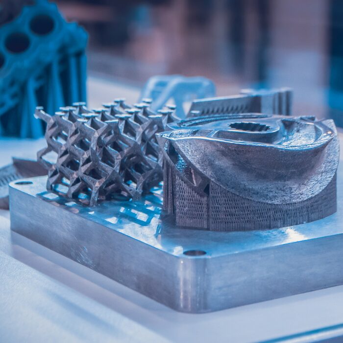 Today, a large number of small launch vehicles are being developed. And at the same time, they all focus on the same consumers. Therefore, we predict a truly tough consolidation in the market for small launch vehicles. Right now, this can definitely be considered an inflating bubble. I think that this direction will experience really difficult times in the next 12-18 months.
And how does this affect Rocket Lab?
We are in a rather unique position and we are the only ones launching rockets right now. So we see a lot of companies doing nothing but promises (these are companies that haven't launched their rockets yet), and people are beginning to realize that these companies they bought launches from will take many years to actually fly. The path to the first flight is in itself very difficult, but the road from the first flight to serial production is no less difficult.
Source
SpaceX, 3d printer, main oxidizer valve part, Blue Origin, 3d printed components in their powerful BE-4 engine, Rocket Lab, Rutherford engines, 3d printing technology, Peter Beck , 3d metal printing
3D copper printing
14. 00
00
Normal
0
false
false
false
0081 X-NONE
Copper is a ubiquitous metal known for its conductive properties. But did you know that you can 3D print it? Check out this article to find out more.
What is this?
Even coins can be 3D printed (but they are not legal tender). (Source: i.materialise.com)
Although metal printing in general is still quite difficult at home. However, there have been significant advances in professional metal printing over the past few years. This is now commonplace in some industries, such as the automotive industry.
Method 1: FDM Printing
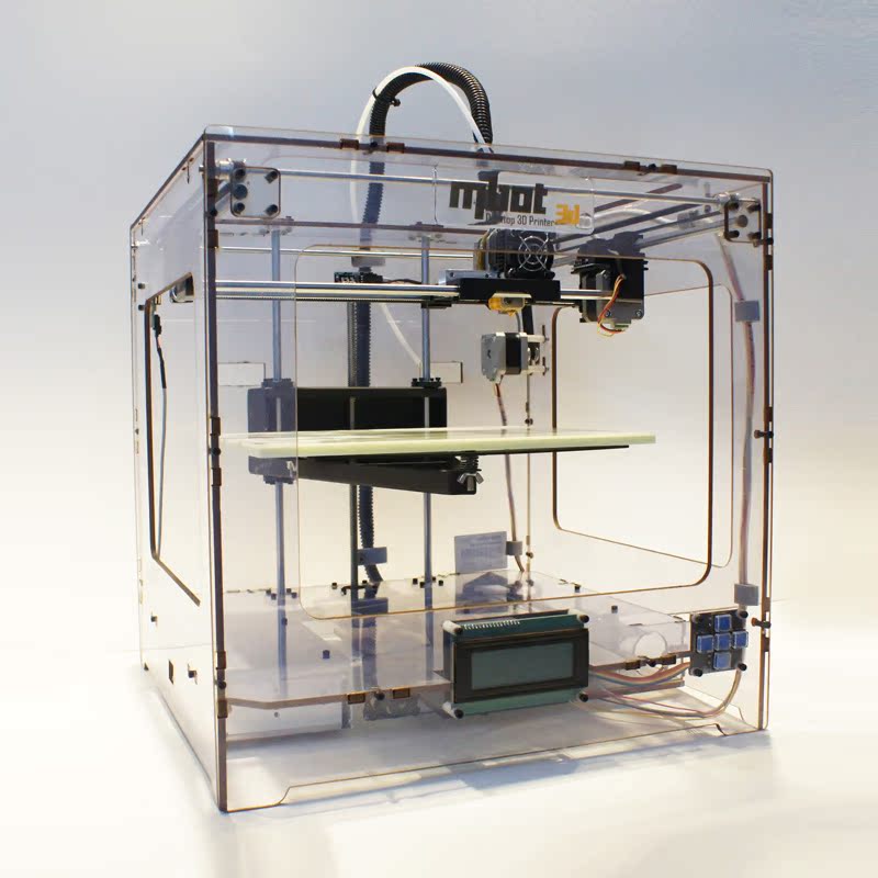
This Filamet copper engine block was printed on a standard FDM printer. (Source: hackaday.com)
In terms of FDM printing, the only real option is to use copper filament. Many try to produce it, but only one company, The Virtual Foundry, achieves 90% metal in their PLA hybrid filaments. The idea behind the filament is that once an object has been printed, it can be fired in a sintering oven to achieve a 100% copper composition.
Of course, one of the big drawbacks of this method is that the loss of the PLA binder causes the part to shrink by 15-20%. However, most details can be adjusted before printing.
After firing the material in a furnace, it retains all the properties of copper, incl. high electrical conductivity.
Of course, this thread does not come cheap. One kilo costs $121, and because of the much higher density of copper, you end up with a lot less filament than you'd expect than if it were 100% PLA.
Unlike conventional PLA, Filamet must be preheated and hung on a low friction spool holder to prevent filament breakage during printing. Also, Virtual Foundry recommends printing slowly (less than 30mm/s) at first.
In terms of performance, the filament can print layers up to 100 microns thick.
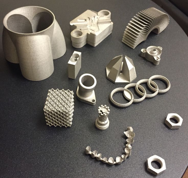
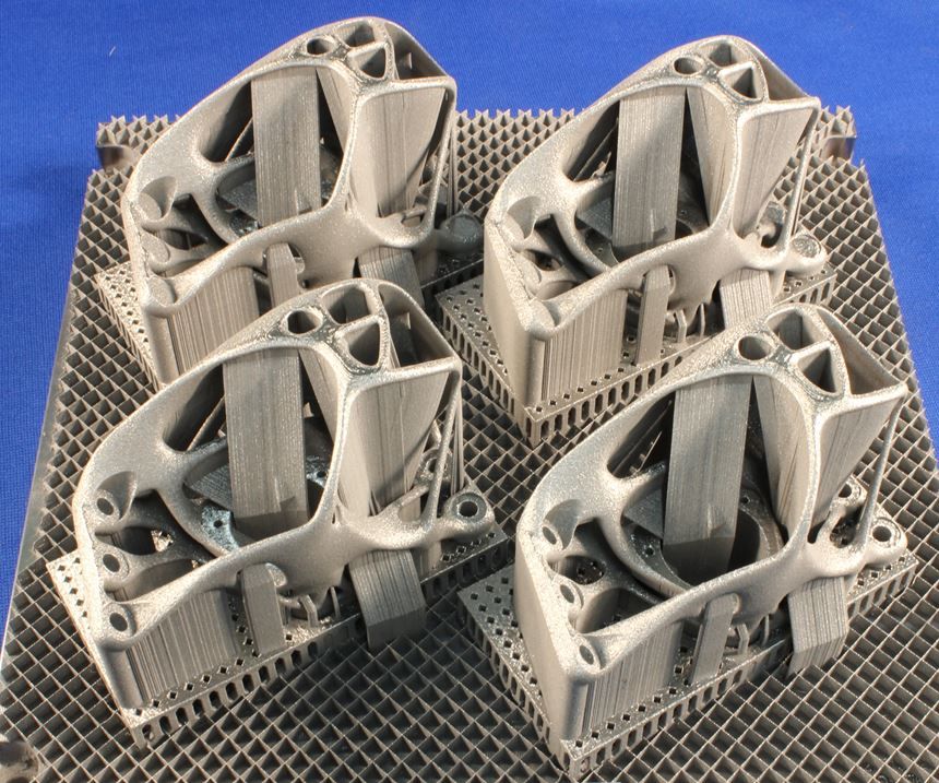
Method 2: Direct Metal Laser Sintering (DMLS)
Parts made using DMLS. (Source: proto3000.com)
DMLS is a laser-assisted process that fuses metal powder into a fully functional 3D part. The powder is deposited and the product is built up layer by layer. After building the part, excess powder must be removed using compressed air in a closed chamber.
This process is quite messy and requires tools similar to those that will be used for a sandblasting system. Health issues should also be taken into account, as it is dangerous to breathe small metal particles.
Buying your own DMLS machine is not an option for most people as these machines typically cost over $100,000. However, various 3D printing companies can print your parts on demand. Despite this low availability, DMLS has many uses, depending on the type of metal used. For example, NASA is investigating DMLS to produce printed rocket parts.
Price: depends on the complexity of the part and the amount of metal used, but in general over $1,000 per kilogram.
Availability.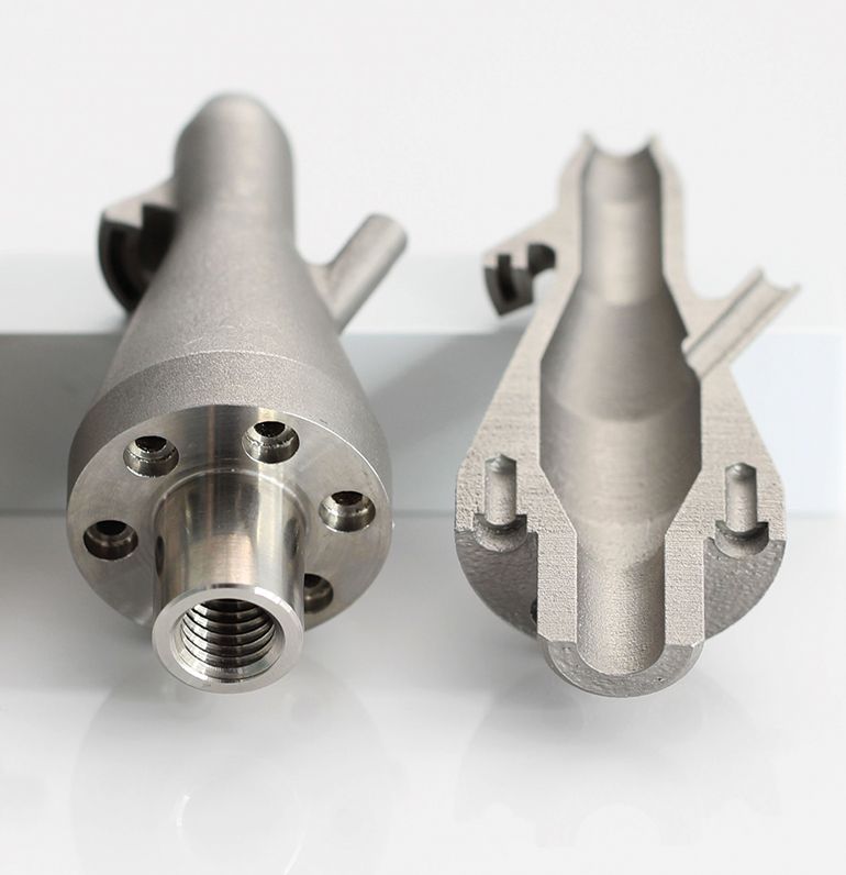 The availability of DMLS technology is essentially zero for a person who wants to purchase their own machine, but it is possible that a 3D printing service will print your part for you.
Performance: The layer thickness is about 38 microns, and the finished metal part has the same properties (conductivity, density, etc.) as the cast metal part.
Method 3: Investment casting
Metal casting. (Source: 3D systems)
Wax casting
Lost wax casting is the process by which an original object created in wax can be turned into a mold to create a part from another material (usually metal). The steps to achieve this goal are as follows:
1. Create an object in wax.
2. Pour plaster around the wax part to create a plaster mold.
3. Place the plaster mold in the oven to burn the wax out of the inside of the mold.
4. Pour molten metal into a plaster mold to create a cast object.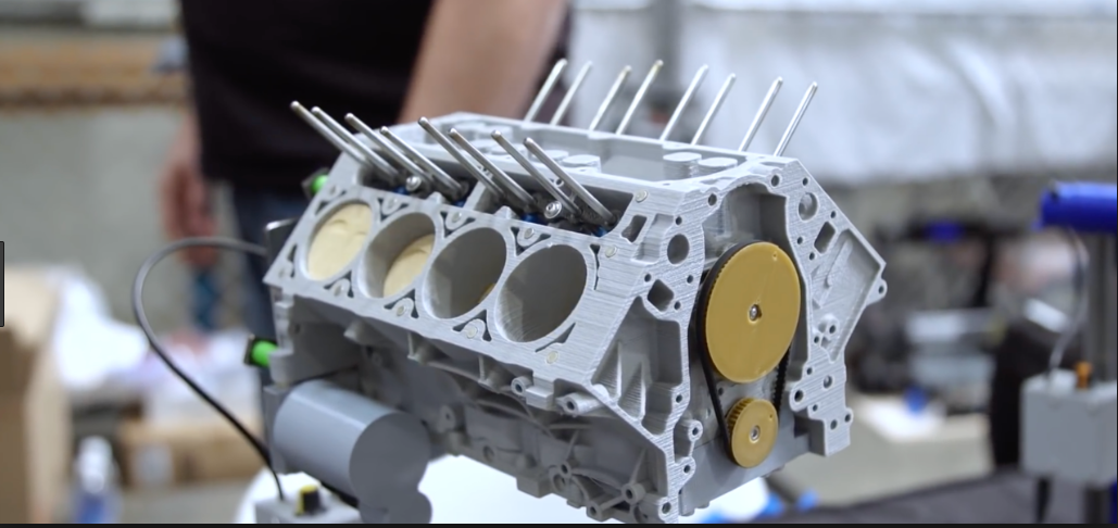
5. Clean the part from the plaster mold.
It should be noted that this investment casting process results in the loss of small parts and results in a finished part smaller than the original wax cast. Therefore, exact dimensions compared to the original part should not be expected without careful consideration of material shrinkage.
PLA Casting
Lost wax casting is done in the same vein with 3D printing, but it is a faster process. You need to follow a few simple steps.
1. 3D printing of an object in PLA. During the design process, access channels can be designed in detail to make it easier to pour the copper into the mold after it has been created.
2. Create a plaster mold around the 3D printed object.
3. Burn the PLA from the inside of the mold.
4. Pour molten metal into an empty plaster mold to create a cast object.
5. Clean finished part.
In terms of cost, printing an object will cost no more than a few dollars (depending on the size of your print). The price of melting PLA depends on whether you are using an existing oven or decide to build your own. Furnaces can cost anywhere from $500 to several thousand dollars, depending on the size and thermal performance desired. Gypsum and sand can be purchased for less than $50, depending on the quantity needed.
Price: Over $600 (as initial investment)
Availability: Oven and casting experience required.
Productivity: Technically, PLA can be printed at 20 micrometer resolution if needed, but such casting features can be difficult.
3D printing: a question of choice (Source: pliustrys.com)
If you want to print on metal but are not willing to buy an oven or pay more than $100 per kilo of metal filament, you can use a 3D printing service. Here are some things to keep in mind before choosing one of the methods:
Does your idea have fine detail?
How much are you willing to pay?
· How fast do you want your product to be made?
In general, small parts (less than 100 microns) cannot be reliably created using lost wax casting or PLA technology due to method limitations.