Servo gripper 3d print
STL file Servo Gripper for Robotic Arm
Writing Machine V2.0 - 2D Pen Plotter
€6.57
2D Pen Plotter - Arduino Writing Machine
€4.48
Motorized smooth Camera Slider
€4.48
DIY LED Panel Light - 3D Printed Dimmable
€1.13
Best 3D printer files of the Gadget category
Large Thomas the Tank Engine - Thomas & Friends
Free
Sony A6000/A7 Hot Shoe Cover
Free
Junak 123 motorbike phone mount
€2
Fab Lab Tulsa Paddle Boat
Free
MBT-70 (German: KPz 70 or KpfPz 70)
€14
censor curse word cigarette holder
Free
Lost in Space Chariot(netflix) /MINI-Z 4x4 Body/(fan art)
Free
Cork Pals: Frankly my Deer
Free
Best sellers of the category Gadget
G17- DD17 Rails Frame
€7. 50
F18 SUPER HORNET - 50 MM EDF JET [RC PLANE]
€12.20
Perritos fantasma / Spooky dogs
€3.25
DJI Avata Bumper
€3.50
WALL KEY HOLDER - EYE (ENTIRE COLLECTION)
€1.88
DJI AVATA GoPro Mount
€2.50
Owl - Wall Key Holder
€1.85
V8 engine print in place
€0.88
App to turn your photo into 10 types of decoration
€3.54
Gato fantasma / spooky cat
€3.25
ELEPHANT PIGGY BANK - NO PAINTING REQUIRED
€3
App to create dual text illusion
€3. 54
54
JEEP WRANGLER PEN HOLDER - 3-IN-1
€1.82
App to create switchable business cards
€3.54
wall key holder (dragon ball)
€1.25
Bone Finger Updated
€6.59
Would you like to support Cults?
You like Cults and you want to help us continue the adventure independently? Please note that we are a small team of 3 people, therefore it is very simple to support us to maintain the activity and create future developments. Here are 4 solutions accessible to all:
ADVERTISING: Disable your AdBlock banner blocker and click on our banner ads.
AFFILIATION: Make your purchases online by clicking on our affiliate links here Amazon.
DONATE: If you want, you can make a donation via PayPal.
WORD OF MOUTH: Invite your friends to come, discover the platform and the magnificent 3D files shared by the community!
▷ servo gripper 3d models 【 STLFinder 】
Servo Gripper
thingiverse
Also i changed the design for the servo spacer to made it thicker and attach it to the rear screws, since the small 2mm screws that i have for the servo are not long enough to reach the top plate. ... Links: [OnShape document with some...
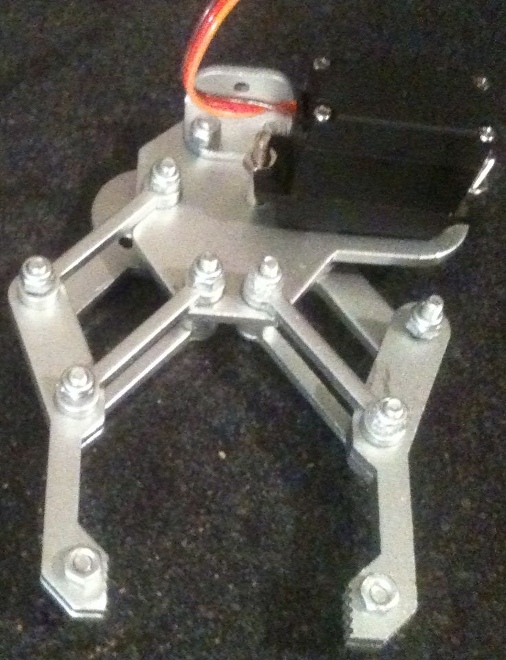
Servo gripper
grabcad
This model was design for work with a SG90 servo for the gripps and a MG995 for rotation.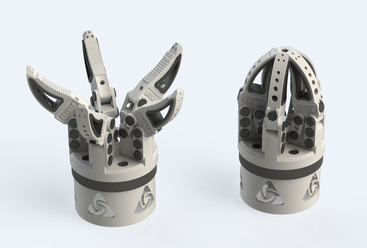
Mini servo gripper
cults3d
This servo gripper is modified for smaller servos than the original edition. Also 4mm plywood is used. ... The work is based on http://www.thingiverse.com/thing:4849 with changes to 4mm plywood, more separators and different gear.
Mini servo gripper
thingiverse
This servo gripper is modified for smaller servos than the original edition. Also 4mm plywood is used. The work is based on http://www.thingiverse.com/thing:4849 with changes to 4mm plywood, more separators and different gear. ... Instructions Cut all...
Servo Gripper (TRAKYA CAM)
grabcad
This servo gripper, 60 kg.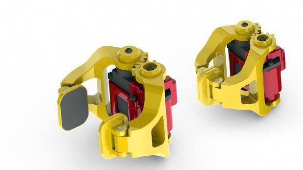 payload, Hyundai HS60 depends on the robot. This robot from production, "raki" glasses are 9 units, conveyor waiting to fill in the boxes 3x3 cell. 1 time in 3 lots, 9 cups puts. ... The cycle time of 7 seconds.
Mini servo gripper
thingiverse
A little video:http://www.youtube.com/watch?v=7CUNx4kPw6w For more pictures and info:http://jjshortcut.wordpress.com/2010/04/19/my-mini-servo-grippers-and-completed-robotic-arm/ Instructions To assemble the gripper you use m3 nuts and bolts. For the...
Mini servo gripper, routerized
thingiverse
This is jjshortcut's mini servo gripper (http://www.thingiverse. com/thing:2415) routerized and adapted for 6.7 mm plywood. I am using a 1.5 mm spiral cutter in 1 mm passes. It appears to work great mechanically speaking (now need to make that servo...
Mini servo gripper Plate
thingiverse
They are done in openscad and require the original files from the Mini servo gripper. There are currently two plates: one for geared parts, another for the rest of the parts. This is so you can print the gears at better quality and to avoid possible...
littleBits-modified mini servo gripper
thingiverse
This is a robot hand part for littleBits servo. . ..You can mount this directly to a littleBits mounting board. This is a modification of jjchortcut's mini servo gripper. ...He did an awesome work!
Standard servo gripper
thingiverse
A gripper compatible with a standard servo. I used a RS 2 J/R servo from modelcraft. My model is made with a 3 axis CNC milling machine but it's also printable. It's made of 4mm hardboard. For a little video:http://www.youtube.com/watch?v=HPPdbNW-OvI...
Simple servo gripper
thingiverse
It works with this servos http://www.miniinthebox.com/mini-9g-servo-with-accessories-translucent-blue_p638990.html You just need to print it and use a screw that is already shipped with the servo, so you don't need any additional hardware.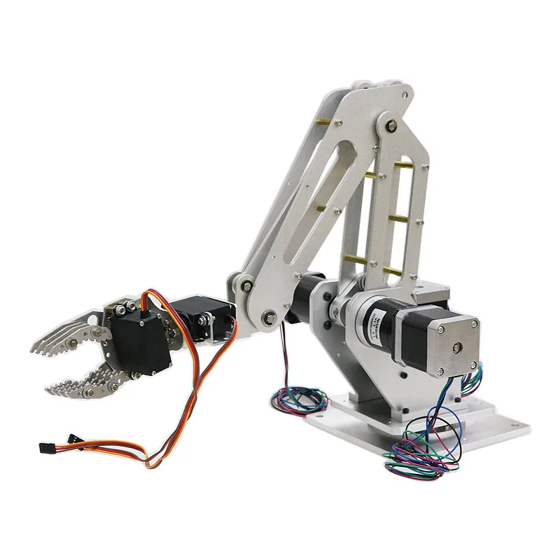 ... Use...
RobotArm - Mini Servo Gripper
thingiverse
This gripper is remixed of [thing:2415](/thing:2415) for this [robotic arm](/thing:1718984), to assemble you need: * 1 x Tower pro SG90s servo or compatible * 7 x M3x18 screws * 7 x M3 nuts, prefer nylock type * 1 x M2x6 tapping screw Video demo:...
Simple Printable Servo Gripper
thingiverse
There is a narrow support column in the middle of the servo hole, that must be cut off, this allows printing without support material. Use a Hitec Hi-55 or similar. Picture shows the gears done with my $200 laser cutter. ...Be sure to check out my.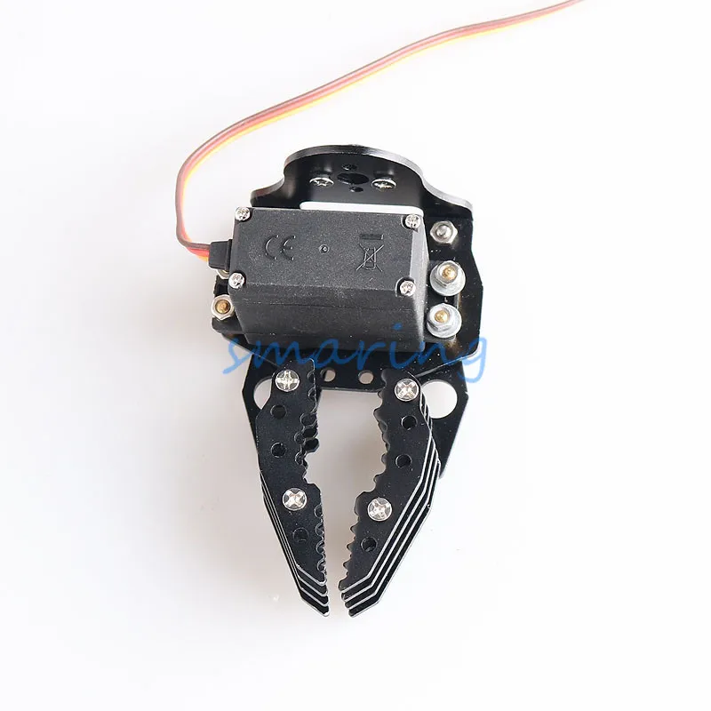 ..
..
Simple servo gripper Mg90
thingiverse
Rafts: No Supports: No Resolution: 0.2 Infill: 20 Post-Printing Requirements To mount the clamp you need: External Parts: 1 x Mg90 Servo 9 x M3 screw with self-locking nuts ( the holes may require an additional drilling work with 3 mm drill bit)...
RobotGeek 9G Servo Gripper
thingiverse
A discontinued RobotGeek Gripper. ...Available for download in .stl and .dxf so you can make your own on a 3D Printer or Laser Cutter! Gripper Getting Started Guide Gripper Assembly Guide
Mini Servo Gripper (Modified)
thingiverse
I just had to modify the base plate that the servo slots through and make a mounting plate for it to offset it as the horn sticks out much more than with the server used in the original design.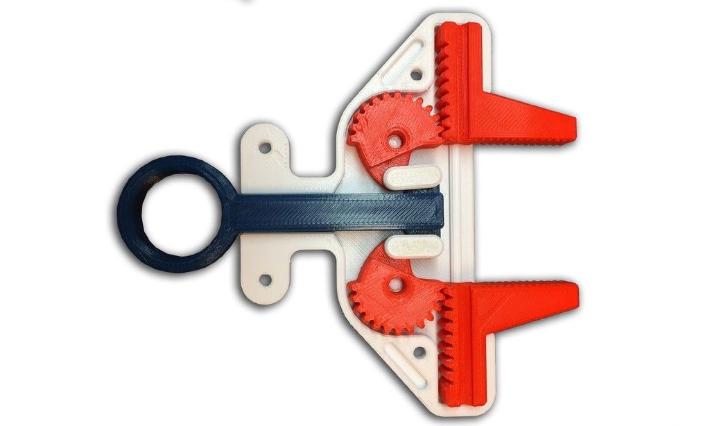 Many thanks to jjshortcut - the original author.
I...
Many thanks to jjshortcut - the original author.
I...
sg90 servo gripper (pinza para servo sg90)
grabcad
sg90 servo gripper, ideal para imprimir en 3D
Servo gripper for cube solving robot
thingiverse
This is the servo gripper for my cube solving robot. https://youtu.be/EGCICLFrrK0 The robot itself can be found here: https://www.thingiverse.com/thing:4978925 The grippers are a modified version of the heavy duty gripper by Kas49:...
Snap-Together 9g Servo Gripper
thingiverse
This is a snap-together version of the classic servo-driven robotic gripper.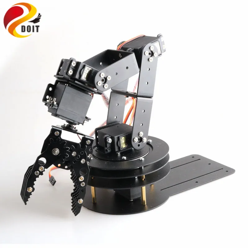 A single screw (usually included with your servo to connect various servo horns) is required to ensure a good connection between the servo and movement lever. Everything...
RobotArm hobby servo gripper mod
thingiverse
Modified gripperBase for MG995 servo actuator. ...Tested with MG995 / MG996 / Futaba S3003 (or clones thereof)
Servo Micro Gripper
thingiverse
Servo Gripper a robotic gripper for micro-servo motors This Servo robotic gripper can be assembled in just minutes with simply a Phillips screwdriver. The gripper kit comprises three parts, assembled using three screws supplied with the kit. ...It is...
Servo gripper Mg90s
thingiverse
Developing toy. ... Did with his son.
Servo Gripper Arm for SG90/ MG90s Servo motor
thingiverse
This is a 3D Printed Servo Gripper made using 3d printed parts and a MG90S Metal Gear Servo Motor. This gripper can pick objects and can be attached on a robotic arm for picking up objects. i have used a servo tester to test the movement of the...
MG-995 Servo Gripper (Ver 1.0)
grabcad
Gripper For MG-995 Servo (Ver 1. 0)Material : AclyricManuf. ...Method : Laser Cutting
3-D Printed Servo Gripper V0.8
grabcad
This is a 3D printed robot gripper that I built for a larger project. ...It is not quite perfectly fitted with the servo but is functional.
Parametric Servo Gripper Not-Lego Brick Set
thingiverse
ABS filament: http://amzn.to/2tzUZoR TPU filament: http://amzn.to/2uzk3Ja SG90-9g Servo: http://amzn.to/2tEdh8p FS90R-continuous Servo: http://amzn.to/2tL3XQG Gearmotor: http://amzn.to/2tE91Wf Also be sure to check out my collection of the best Lego...
Simple 3d printed 9g servo gripper
thingiverse
A simple 3d printed claw that I designed to be used with a 9g servo.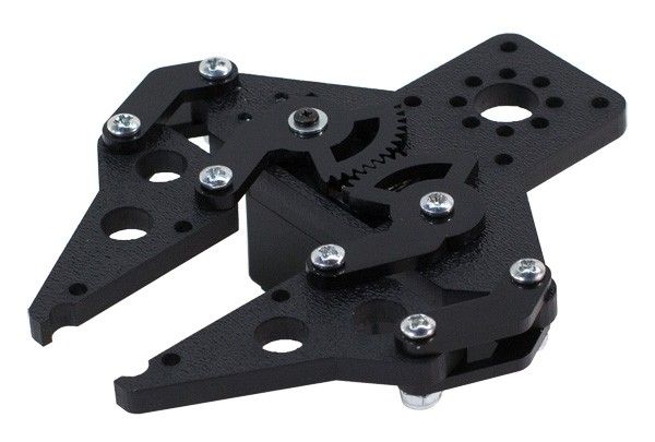 ...It keeps the servo parallel to te claw action in order to reduce the weight in the arm. ...
https://www.youtube.com/watch?v=FNFmIbqV8nc
...It keeps the servo parallel to te claw action in order to reduce the weight in the arm. ...
https://www.youtube.com/watch?v=FNFmIbqV8nc
Attachable gear for 9g servo gripper
thingiverse
Note: This is the gear only, the other components are available from the original. ... You may need some force to attach the gear to the servo, but after that it should fit really well.
SG90 3d printed 9g servo gripper
thingiverse
...
-The two-piece claw set made was modified into one piece and longer to grab a more significant range for larger objects.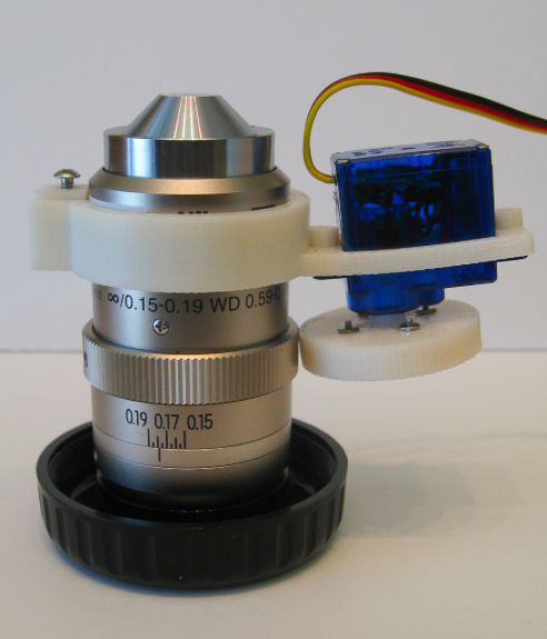 -Added a base to the main frame that secures the servo in place so that you can place the claw evenly on a flat service.
3D Printable 6 DOF Robot with Servo Gripper
grabcad
And exactly as I like it: 2 cubes of sugar and stirred well.The blue, gray and black components are 3D printed, the servomotors ordered from China.Overall, the articulated robot has 6 axes and a servo gripper. It is currently being driven by Pololu...
Creation of the base of the SG90 servo bracket, preparing the model for 3D printing.
In this article, we'll show you how to create an SG90 servo bracket base in Blender and prepare it for 3D printing. The SG90 servo drive is used in robotics, also to control small machines.
In this article, we'll show you how to create an SG90 servo bracket base in Blender and prepare it for 3D printing.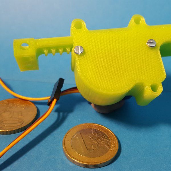 The SG90 servo drive is used in robotics, also to control small machines. This base is the lower part of the bracket, the whole bracket is as follows:
Let's place the base drawing, on which we will create our model, in the window UV / Image Editor .
We will create a model from a regular cube. Since we will create the model by dimensions in millimeters, we need to activate Metric , since by default all objects created in Blender have dimensions in units (Blender units of dimensions). Go to tab Scene and select the metric system.
But it is worth considering that if we switch to Edit Mode, then our sizes will be different. To make it all right, in Object Mode we need to press Ctrl + A and apply scaling.
You can view the dimensions by activating Display the length of selected edges.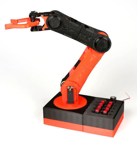
You can also select Angle display if needed. You can also use the Ruler to determine the dimensions. To do this, go to the tab Sketch Pencil and select Ruler/Protractor .
Let's move on to our model.
Set the dimensions of the base: 37*33*3 mm.
You can specify other dimensions, it all depends on what you will attach this base to. It can be cut and cut, or another other form.
We need a base with standard dimensions, so the model will be similar to the one in the picture.
Now using the edge loops Ctrl + R create an intersection where the center of the top of the base will be placed.
Activate Vertex Select and select this central vertex.
Next, to bind the cursor to the selected point, press Shift + S and select Cursor to selection . Now the cursor is located in the place from which we will build a cylindrical element.
Press Shift + A and create Circle . We set the radius of the outer part of the cylinder, in our case it is 12 mm.
Next, apply the tool Fill ( Alt + F ). Select our ring and the face on which we want to place it and press Alt + F . Now our circle is part of our model.
Let's remove the initial edges so that we don't get errors when forming STL file .
Now let's create the wall of the upper part of the base. To do this, select the circle and hold down E onwards S . The wall is ready. Now fill in the circle by pressing F .
Next, we need to create a socket for the cross, which fixes the shaft.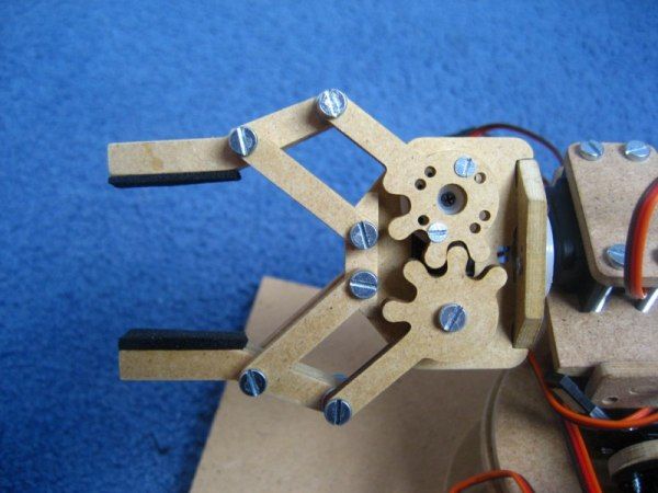 The crosses themselves come with a servo.
Activate the cursor binding to the selection again and create Plane . Scale it a bit with the key S .
Inscribe a new plane in the plane of the circle ( Alt + F ). Let's delete the initial edge again.
Next, subdivide the square plane. Press W and select Subdivide.
Now select the center edges and apply the Chamfer tool ( Ctrl+B ).
Let's combine a little with scaling ( S ) and now combine the planes into one ( F ), from which we will make a nest.
Next, create the wall of the nest, using extrude ( E) and scale ( S) . And we extrude ( E ) to the desired height along the axis Z our nest.
Do the same with the circle. Select all faces and extrude ( E ) in Z to the desired height. Ours is 9mm.
Now let's create holes in our base. We will create them using Boolean Modifier.
Select the base face for the crosses, place the cursor in the center (as described above) and create a cylinder in this center.
To make the cylinder a separate object, to which we could then apply a modifier, we separate it from the general model by pressing P and selecting By Selection . Go to Object Mode , select the base, select the Boolean modifier, set the operation to Difference, the object is our cylinder . And click Apply. Delete the cylinder and see that we have a hole.
Do the same for the mounting holes. Let's just simplify a little, and before applying the modifier Boolean , after creating and separating the cylinder, apply the modifier Array , thereby spreading it to all corners.
In the same way, we will create holes for fastening the cross. Since the dimensions are not so important for us and there is no need to measure the location of the hole to a millimeter, we place the created cylinder “by eye” and also create holes using the modifier Logical .
Now let's check the resulting model for printability. To do this, select it and click on tab 3 D - print.
Click on the button Integrity and see that the program did not find errors (zeros below).
Next, export the file to STL -format through the File menu.
High speed milling 3D printer with linear drives
Above and below what is printed on Sodick 3D printers. Examples only:
OPM250L and OPM350L 3D printers
Both models are a full-automatic additive laser 3D metal powder printer + high-speed (45000 rpm) milling center in one unique machine, which has no analogues.
For the first time, Sodick has combined high-precision additive laser printing with metal powders and high-speed milling. Inside the working chamber, the metal powder is evenly welded by a laser beam that scans the part (layer-by-layer welding).
Sodick used a Yb laser (ytterbium fiber laser) up to 500W in its printers. The high power of the laser made it possible to increase the speed of 3D printing. The printer prints the most complex metal parts that are either impossible or very difficult to manufacture using another method. The built-in high-speed (45,000 rpm) milling center not only gives the most complex parts a “presentation”, but also makes it possible to obtain parts with amazing accuracy and mirror surfaces in one machine.
| 3D printer specifications | OPM250L | OPM350L |
| Max. workpiece dimensions | 250 x 250 x 250 mm | 350 x 350 x 350 mm |
| Axial movements X x Y | 260 x 260 mm | 360 x 360 mm |
| U travel | 260 mm | 344 mm |
| Internal dimensions of the working chamber | 290 x 290 mm | 390 x 390 mm |
| Z axis spindle travel | 100 mm | 100 mm |
| Metal powder stock | 90 kg | 300 kg |
| Nitrogen supply | 32 Nl/min | 90 Nl/min |
| Machine dimensions (excluding peripherals) | 1870 x 2230 x 2055 mm | 2200 x 2485 x 2220 mm |
| Machine weight (excluding peripherals) | 4500 kg | 5800 kg |
| Laser | ||
| Laser type | Yb fiber laser (ytterbium fiber laser) | |
| Laser wavelength | 1070 nm | |
| Max laser output | 500 W (1000 W = OPTION) | |
| Laser scanning | galvanic scanning (galvanizing) | |
| Milling center | ||
Max. main spindle speed main spindle speed | 45,000 min - 1 | |
| Main spindle maximum torque | 0.8 Nm | |
| Number of tools | 16 | 20 |
| Tool holder | HSK–E25 | |
| Axial / Simultaneous | XYZUB + spindle / max 4 axes | |
Examples of 3D printing on Sodick additive laser printers with high speed milling:
With the launch of the OPM250L and OPM350L Additive Milling Centers, the metal 3D printer and high-speed milling in one machine, Sodick has actually introduced a complete set of technological solutions
ALL IN ONE .
Sodick provides end-to-end support for all processes from design to injection molding, linking it all with advanced technologies, including EI wire-cutting machines, EI jig-piercing machines, injection molding machines, as well as machining centers.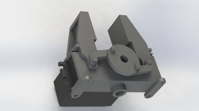 Performing additive laser manufacturing of parts and tool molds and high-speed milling in the same machining center allows you to obtain complex shapes with a high degree of freedom, as well as high-quality finishes that are simply impossible in conventional metal cutting operations
Sodick CNC and CAM system with “Z-asso” functions.
After the tool mold is designed using a 3D CAD system that supports the design of cooling channels, the temperature variations of the plastic are simulated using the CAE system. The 3D CAD data of the optimized shape is then loaded into a CAD with “Z-asso” functions, which generates CNC programs and directly transfers this to the LN2RP computer CNCs.
Settings
Laser processing
Tool management
Easy parameter setting for mold making. Mold making data can be imported by simple drag and drop procedure.
K-SMC - Sodick motion controller.
Absolutely precisely controls any movements of linear motors (LM) by computer CNC commands (CNC).