Scanning 3d printer
How to Choose the Best 3D Scanner to Use With Your 3D Printer
3D scanning has an important place at the beginning and end of 3D fabrication workflows. Engineers, product designers, and researchers use 3D scanners as a faster and more efficient way to start constructing digital models, whether by incorporating existing designs via reverse engineering, digitizing hand-sculpted clay designs, or referencing the exact shape of the human body.
After fabrication, 3D scanning can support quality control and help to verify the accuracy of a 3D printed part, or, after the part has been used, a scanner can reveal how it’s performed—a scan of a deformed part can show you where to reinforce the design in the next revision.
With such a wide range of product options from handheld 3D scanners to desktop 3D scanners, it can be difficult to choose the best 3D scanning system that’s right for your application and budget. In this post, we explore the most important factors to consider when purchasing a 3D scanner and showcase some of the key applications that are empowered by combining 3D scanning and 3D printing.
White Paper
3D scanning and 3D printing workflows can be applied to replication and restoration, reverse engineering, metrology, and more. Download our white paper to explore these applications and learn how to get started.
Download the White Paper
There are multiple scanning technologies currently on the market, all offering their own advantages and weaknesses.
Laser triangulation uses light projected onto the object to take up to millions of measurements (dots) per second. The light reflected from the dots back into the scanner’s sensor to help it capture the geometry of the object. These types of scanners are often the most accurate, and are great for highly detailed parts that have opaque surfaces.
Laser triangulation scanners do have limitations. For example, this technology is not used in most portable scanners because the laser dots need to project from a stable source, and the source has to be kept a close distance from the scanned object. Laser triangulation scanners don’t always work on transparent or shiny surfaces either. Typically, they require reflective markers to be applied onto the object, which need to be removed after use and can be an obstacle depending on the object being scanned.
Finally, the laser dots can be harmful to human eyes, so it is important to use extra safety precautions when scanning body parts with a laser triangulation system, or to check with your scanner manufacturer to make sure the device is eye-safe.
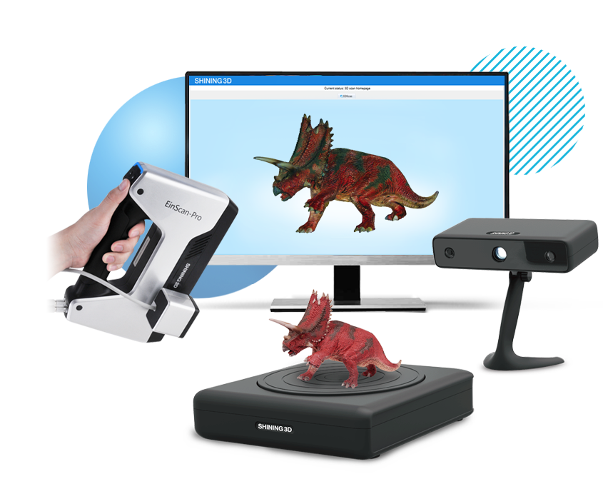
Structured light scanners (also known as white light scanners or blue light scanners) generally use a projector with two cameras at angles on either side. A pattern of light is projected and laid over the component being scanned, the cameras capture the ways in which the object deforms the light pattern, and then multiple images are integrated into a single 3D snapshot.
Structured light scanners are available in both stationary and portable format—the technology is the most commonly used process for handheld 3D scanners.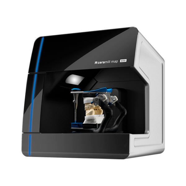 Structured light scanners are far more common in medical applications, since it is safe to use on both humans and animals and excels when an object is not perfectly still. Traditional white light scanners have been slower to scan than laser triangulation scanners.
Structured light scanning is the most commonly used technology in handheld 3D scanners.
Depth-sensing cameras project a field of dots in infrared (IR) to sample a 3D scene. Depth-sensing cameras are simple to use and are the least expensive scanning option, but their accuracy and resolution are low, and fine details are sometimes lost. Large objects may be captured with depth-sensing cameras, but accuracy declines with increased distance from the subject and at steeper angles to the camera.
Photogrammetry means the act of deriving precise measurements from photographs. It involves taking a set of overlapping photos of an object, building, person, or environment, and converting them into a 3D model using a number of computer algorithms.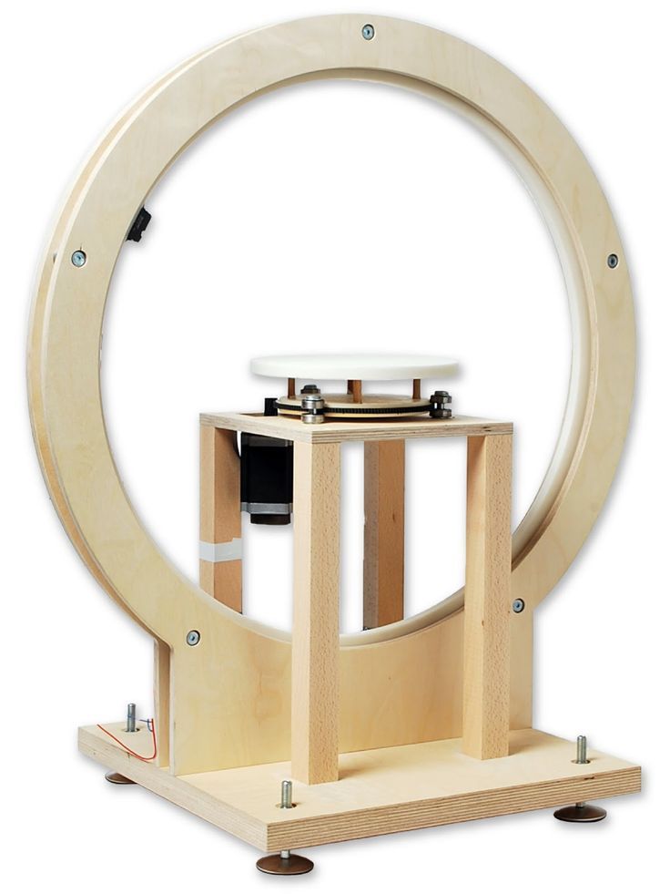 This is the most commonly used method when creating a 3D scan with a smartphone, since modern phone cameras are capable of capturing and combining a large numbers of photos. Photogrammetry should be considered the least expensive and least accurate method for creating 3D prints, and is not suitable for serious business applications.
LiDAR (light detection and ranging) sensors can be found on some higher-end smartphones and tablets, such as the latest versions of the iPhone Pro and the iPad Pro. This has made the iPhone and iPad viable scanners for those with only occasional scanning needs, offering performance a step above devices that only have access to photogrammetry. Applications that generate 3D mesh files via your smartphone’s or tablet's camera should be seen as the floor for entry-level scanning; users should expect additional work in their CAD software to remove gaps in meshes and improve the 3D model for applications like sending it to a 3D printer. Smartphones use fewer light points when scanning objects, resulting in less detail than a true, stand-alone scanner. iPhones are good substitutes for scanners if you have significant CAD design ability or need to transfer basic models into a digital space.
WEBINAR
Watch this webinar with Peel 3D to explore how to integrate 3D scanners into your 3D printing workflow to elevate your product development process.
Watch the Webinar Now
Scan accuracy varies considerably between scanner technologies, and higher accuracy generally comes at a higher cost. The required tolerances of your final part can be a helpful guide for determining your accuracy requirements for a 3D scanner.
| High Price, Highest Accuracy ($15,000 and more) | More Affordable, High Accuracy ($12,000 and under) | Low price, Low Accuracy |
|---|---|---|
| Zeiss T-Scan Hawk Scantech Simscan EviXscan Optima+ M Creaform HandyScan 307 Silver Series | peel 3d peel 1, peel 2 & peel 2-S FARO Freestyle 2 Polyga Compact S1 | iPhone Pro and iPad Pro Structure Sensor Matter and Form 3D Scanner V2 Revopoint POP |
With accuracy in the range of 0.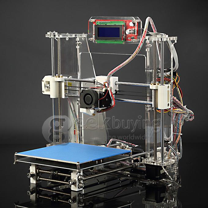 1 mm or better, laser and structured light scanners are a good fit for professional applications and alongside high-resolution 3D printers. Formlabs stereolithography (SLA) 3D printers (such as the Form 3+) produce parts at a similar accuracy, and with a similar printable area, to the scan volume of many desktop 3D scanners.
Besides the accuracy between measured points and their actual location, scanners also vary in terms of resolution, which is the distance between captured points at a given scan distance. This means that details on the scanned object that are smaller than the scanner’s resolution won’t be captured. For example, a highly accurate 3D scanner with a lower resolution might detect the general shape of jewelry on a statue, but not clearly show individual details on a ring or necklace. Depending on your project requirements, this may or may not be a dealbreaker.
An easy way to remember these metrics is: accuracy is the measurement error between the part and digital value. Resolution refers to the density of measurements.
Accuracy can mean slightly different things depending on the manufacturer and 3D scanning technology. For example, the accuracy of handheld scanners depends on the distance to the subject and the quality of scan reconstruction, while desktop scanners have consistent accuracy within the constrained scan volume. If you are considering buying a 3D scanner for precise measurement, make sure to compare like to like.
In general, structured light scanning provides the best resolution and accuracy when compared to laser scanning. For some artistic use-cases for 3D scanning you may need a lot of detail, while overall accuracy is less important—especially if you don’t require your part to fit precisely with other parts in an assembly. In these cases, photogrammetry is an excellent low-cost option to explore.
Both depth-sensing cameras and photogrammetry are a good solution for scanning large objects in order to create 3D printed scale models and also offer enough accuracy for capturing the shape of the human body.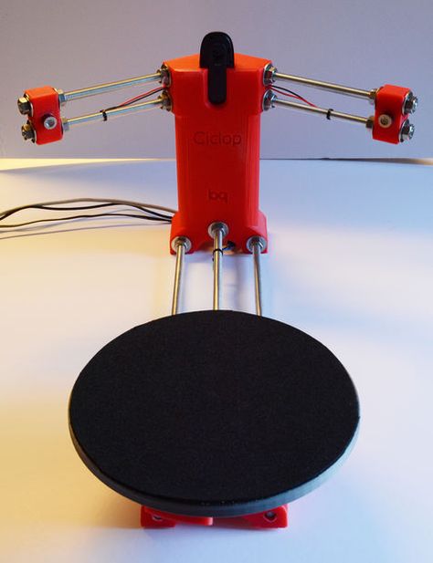
Several entry-level laser scanners are available using technology similar to higher-end systems. These scanners are a great way to start replicating small objects at 1:1 scale. As one would expect, the accuracy of entry-level laser 3D scanners is lower than a high-end scanner, but they can easily provide enough detail to replicate small decorative objects and figures where accuracy is not critical.
If you only have occasional 3D scanning needs, digitization services can scan your object, as well as perform CAD translation and accuracy inspection.
The area that a 3D scanner can capture varies significantly between scanners. Find a scanner that fits your size and resolution requirements without too much overhead, as cost typically increases with scan volume.
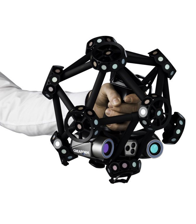
Handheld scanners can be manually moved around the object and have fewer size constraints than desktop models. Most inexpensive handheld scanners can capture objects from the size of a basketball to an entire room. High-end handheld scanners have an even wider range, and fill the niche for all objects that require precise measurements, but cannot fit in a desktop scanner. Handheld scanners are also able to capture objects nearly instantaneously, which makes them well-suited for taking human measurements (where the subject is not perfectly still) for ergonomics and medical applications.
If the area of the model can’t be seen by the scanner, it will cause a gap in the model. You can automatically repair small missing sections with most scan software programs to create a 3D printable model. However, repaired holes are rarely accurate to the original object. For parts that demand close to perfect accuracy, auto-repair of gaps or holes will not be sufficient. Read our MeshMixer tutorial for advanced tips to edit and repair 3D files for 3D printing.
Many scanners use turntables to increase what the scanner can see. The sophistication of a scanner’s turntable affects how easily and completely the object is captured: some scanners have the ability to move the object around multiple axes, imaging the object from more angles. This feature is important when reverse engineering plastic parts with deep recesses and ribs, which are impossible to capture from a single angle.
Scanners may rotate the object to capture occluded areas. Red regions are occluded and will be missing in the scan. Areas with deep relief are difficult for a single axis turntable to fully capture due to occlusion.
Cost concerns are straightforward; how much you are willing to spend on a scanner will reflect your business’s budget and how often the scanner is going to be used. Higher cost scanners will be able to capture small objects and create highly-detailed meshes that don’t require significant touch-ups in CAD software. Handheld scanners are also often on the higher end of the price range, due to their portable nature. The low-cost scanning market offers a wide range of options, but you have to know what to look for.
Use this flowchart to determine what scanner you need based on accuracy, scan volume, and budget.
Download the high-resolution version of this infographic here.
A 3D scanner expands the capabilities of a 3D printer, allowing you to replicate the shape of almost any object. Together, the two technologies create a powerful, digital workflow that can simplify and sophisticate processes in a range of industries.
The output from a 3D scanner is a mesh of triangles representing the surface of an object at a real-world scale. In some cases, the scan can be used directly to replicate objects without any CAD work. A hybrid workflow can also be powerful, where solid CAD models are combined with scanned 3D models. For example, customized ergonomics capture a physical imprint of a part of the human body, and integrate them with a mechanical design.
3D scanners are also valuable tools for measuring the accuracy of manufactured objects. Many factors affect 3D print accuracy, and metrology-grade 3D scanners provide a clear picture of how a material performs for demanding applications.
A variety of powerful workflows are enabled by combining a 3D printer and a 3D scanner:
- Reverse engineering to create replacement parts, products with custom ergonomics, and more.
- Replication and restoration of parts, especially in art and jewelry.
- Consumer audio for creating custom earpieces.
- Dental and medical applications, and how 3D scanning is enabling patient-specific workflows.
- Metrology to validate and measure the accuracy of manufactured objects.
Webinar
Watch this webinar for a detailed look at how to start using 3D scanning to improve part design and production when paired with reverse engineering CAD and 3D printing.
Watch the Webinar Now
3D scanners and 3D printers are essential parts of digital workflows across industries. Download our white paper or watch our webinar to get a detailed look into how to start using 3D scanning to improve part design and production and learn how to pair 3D printing and 3D scanning to empower a variety of workflows in engineering, product design, and more.
Learn more about the 3D printer side of the equation: get to know stereolithography (SLA) and selective laser sintering (SLS) 3D printing technologies and see Formlabs advanced 3D printing materials for yourself with a free sample 3D printed part.
Explore Formlabs 3D PrintersRequest a Free Sample Part
How to Use 3D Scanning and 3D Printing for Reverse Engineering
Reverse engineering is a powerful way to create digital designs from a physical part, and can be a valuable tool in your prototyping toolkit alongside technologies like 3D scanning and 3D printing.
3D scanners measure complex objects very quickly, and can speed up your design workflow tremendously when real-life references are involved. With the ability to capture and modify physical shapes, you can design 3D printed parts that fit perfectly on existing products of all kinds. 3D printed jigs allow you to repeatedly locate a drill or saw, or assemble parts precisely with adhesive. Create close-fitting, reusable masks for sandblasting, painting, or etching.
In this post, we’ll walk through the step-by-step reverse engineering process for an aftermarket digital gauge and explain how to scan a part for 3D printing, with tips along the way for using the right reverse engineering tools, from CAD software to to 3D scanners and 3D printers.
For a full breakdown of 3D scanning workflows and technologies, download our white paper.
Download the White Paper
Looking for a 3D scanner for your 3D printer? Read our detailed guide on choosing the best 3D scanner to use with your 3D printer.
One of the biggest challenges people encounter when converting physical objects to digital is a major incompatibility between two different types of 3D models: meshes and solids.
A 3D scanner outputs a mesh, rather than a constructive “solid” model. Meshes need to be reverse engineered to be made editable.
Meshes are the main output of all 3D scanners, and the format commonly understood by 3D printers (STLs). A mesh represents the surface of a shape with a large number of triangles, connected edge to edge. Mesh models don’t contain any information about the object, besides the position of the triangles that define the shape.
On the other hand, engineers are trained to work with solid models. Solid models hold information about how an object is designed, and this information is explicitly encoded into the model as features in a ‘stack’ of logical steps. In solid CAD, it’s possible to change the dimensions for a single feature, and the rest of the model will update to accommodate the change.
Since meshes lack information about the construction of the object, the ways you can alter a mesh model are limited—CAD software like Solidworks and Onshape can’t directly modify meshes. If you need to make major modifications to the underlying design of a scanned part, the mesh needs to be converted to a solid CAD drawing: this process is reverse engineering.
Reverse engineering is important when you want to create new parts that reference or incorporate older designs, where the original CAD design isn’t accessible.
For example, you can create replacement parts that match the original design of damaged existing pieces, or use reverse engineering processes to integrate complex surfaces from existing objects into 3D printable jigs, which are useful when modifying mass manufactured and handcrafted products.
To demonstrate the basic steps in a reverse engineering workflow, let's take a look at the process for creating an assembly jig for an aftermarket digital gauge that fits onto the air vent of a Volkswagen Golf.
Spray coat the object with a temporary matte powder to improve scan accuracy. Even slightly glossy surfaces tend to degrade scan quality, while reflective and transparent surfaces cannot be scanned at all without a matte coating.
Use a temporary matte powder to improve the scan accuracy of your object.
Use a high accuracy 3D scanner to capture the important sections of the part. Tabletop structure light or laser scanners are the right tools for the job, with accuracy of ±100 or better.
Learn more about how to choose the right 3D scanner for your application in our 3D scanning white paper:
Note: You may need to orient and re-scan your object several times if the object has deep recesses.
Some scanners produce extremely large mesh files, which will make later steps grind to a halt.
Scanner software repairs small gaps and simplifies the scan, making the data more manageable in CAD. Try to reduce the model as much as possible without destroying important details.
Tip: If you need more control, Meshmixer is a great choice for refining scanned meshes.
Import the mesh into CAD software equipped with reverse engineering tools. Geomagic for Solidworks is a powerful choice for resurfacing complex, organic shapes.
If you are reverse engineering a part with simpler flat surfaces, Xtract3D is a less expensive, lightweight alternative.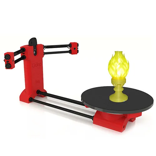
In this step, move and rotate the scan mesh into alignment with any existing design components.
Tip: Make drawing easier by rotating and aligning your scan to face the orthographic view directions.
There are three paths to extract the shape of the scan in order to create a solid model that is editable with CAD tools: semi-automatic surfacing, automatic surfacing, and manual redrawing.
Semi-automatic surfacing
Complex curved surfaces are difficult to manually draw, so you may choose to use semi-automatic surfacing. This function generates surfaces that fit to detected regions of the scan. By varying the sensitivity of the surface detection function, different surfaces will be found.
Tip: Geomagic for Solidworks detects surfaces on the scan to fit 3D curves. Use a “brush” to manually add or subtract areas on the scan from each region.
You may need to repeat this process several times with different sensitivity settings to detect all your surfaces. These surfaces can then be trimmed and knit together to create an editable solid.
Use semi-automatic surfacing to re-create curved shapes when you want maximum editability later on, and when sharp edge accuracy is important.
The re-surfaced result, after trimming.
Automatic surfacing generates a solid model from any watertight scan. You can use standard CAD tools to subtract and add to this auto-surfaced body, but it will be more difficult to move basic features around on the body itself.
You may not need control over edge placement. For example, if you are scanning a part of the human body to create custom ergonomically-shaped products, or want to create a jig to precisely or repeatably modify a handmade object. In these cases, automatic surfacing is a great way to save modeling time.
Note: Compare the results of a automatic surfacing to semi-automatic surfacing: some accuracy is lost, especially around sharp edges.
For simple features such as bosses, holes, and pockets, it’s usually fastest and most accurate to redraw the features using the scan model as a reference. Reverse engineering software allows you to create sketch planes aligned with flat surfaces on the scan and to extract cross sections from the scan mesh, which helps you match the shape of the original object.
Once the scan has been converted to a solid, it can be subtracted from another solid body to create a jig that securely holds the original part.
The design of the new gauge component also references the dimensions of the scan, using curves extracted with semi-automatic surfacing.
Printing the jig on a Formlabs stereolithography (SLA) 3D printer gives you a high degree of accuracy comparable to the output of engineering-grade 3D scanners. Use Formlabs Rigid 4000 Resin for its strength and precision.
Once these steps are complete, the 3D printed jig is ready to use to assemble the new gauge onto the OEM air vent.
The final 3D printed assembly jig, printed in Rigid 4000 Resin.
3D scanning at home. Cheaper and easier than ever!
In the world of 3D technology, scanning is the yin to the yang of 3D printing. While the printer turns computer models into real things, the scanner turns real things into computer models. Along with sketch-based modeling, 3D scanning - in which a real part is scanned into a model in a computer - is another technology for preparing prototypes for subsequent printing.
Advanced 3D scanners are available, but they can be quite expensive and sometimes even more expensive than professional 3D printers.
Fortunately, today there are home 3D scanners that can be used to achieve outstanding results. Today, there are three scanning methods: laser line scanning, structured-illuminated scanning, and image-scanning modeling.
Line laser scanning.
Probably the most popular scanning method for personal scanners. It obtains data about the model by illuminating it with a laser beam. These scanners work best with a neutral background, such as an all-white back set at an angle of 90 degrees. Such a background is inexpensive to make, and scanners based on this technology are cheap. The addition of a 360-degree rotating platform on which the scanned model can stand can greatly improve the quality of the scan.
When everything is ready, you simply turn off the light, illuminate the model with a laser from all sides, the software does the rest.
Although it is possible to use, for example, MATLAB to convert raw scanned images obtained in this way into a full-fledged 3D model, since 2006 the German company David Vision Systems began to develop special low-cost software for this purpose. This software simulates a 3D model in real time, and you immediately see the result of your work. It composes images taken from different angles and forms a 3D model in a format that is convenient for you. The latest versions of the software also support structured-illuminated scanning (see below). You can even use the free trial version to try it out.
Patterned Illuminated Scanning
This method combines a light projector, digital camera and image analysis software for the 3D scanning process and is generally faster than the line laser method.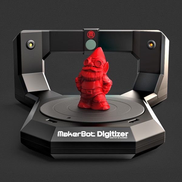 An additional plus is that there is no need to prepare the background from behind. The projector imposes a certain light pattern on the scanned model, often a grid of light and dark stripes, so that the program can determine the shape and coordinates of the object, depending on how the light pattern is distorted on it. The light pattern can be both visible and made in the form of infrared radiation, which you will not even notice.
Infrared scanning has its advantages, for example, because this radiation does not interfere with external light radiation. For example, the Microsoft Kinect device for the XBOX gaming platform uses exactly the method of structural lighting through infrared radiation.
Prior to the use of infrared radiation, ordinary visible color was commonly used. Using this technology, for example, Radiohead's video for the song "House of Cards" was filmed in 2008. The software that supports structured-illuminated scanning is David's software, as mentioned above, as well as ThreePhase, a utility designed specifically for working with structured-illuminated scanning.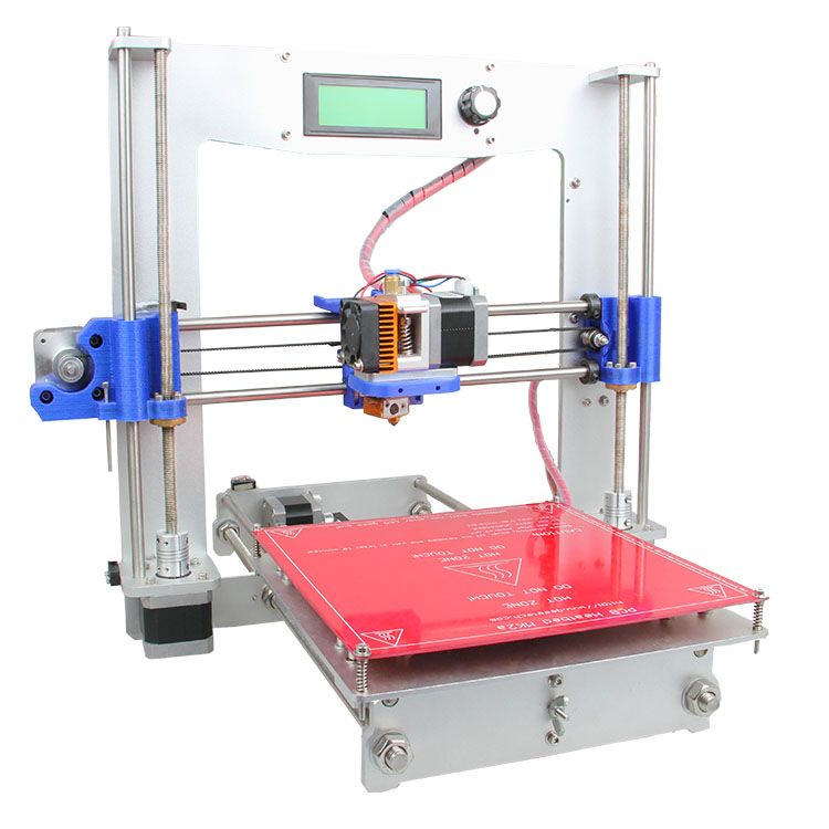 Most programs are usually written for Mac OS X, but ThreePhase can run on all platforms - Mac OS, Windows, Linux.
However, since the introduction of the Kinect by Microsoft in 2010, scanning at home has changed a lot. After several years of development, as well as millions of dollars invested in its research, the Kinect device was obtained, consisting of five elements: right and left microphones, an RGB video camera, an infrared radiation projector, and a monochromatic sensor suitable for a laser. A pair of sensor / laser and allows you to scan and analyze the movement of a person.
In general, the release of the Kinect device prompted many to develop this technology, including in the field of 3D scanning. Against this background, as well as the inexpensive price of the device, interest in structured-illuminated visible light scanning has completely disappeared. Kinect is an incredibly powerful device at a very cheap price and is a great alternative to visible light. At the time of writing, the Kinect sensor costs about $100.
Among all the programs for 3D-scanning, one of the leading programs is the ReconstructMe program from the Austrian company Profactor. This is a quality commercial product that can easily be used for personal purposes. ReconstructMe scans the model immediately at its actual scale, so no further scaling is required. Unfortunately, the program is only available for Windows.
Skanect from the French company Manctl is another popular program that works with both Windows and Mac OS.
Modeling based on image scanning
If you have many photos of the same part from all angles, then special software will convert them into a 3D model. This method is sometimes called photogrammetric, and it has often been used in forensics to analyze crime scenes, car accidents, and so on. based on conventional 2D photos. In this method, the most important thing is to choose the right photos, shooting angles, and also choose the right software.
Programs like Eos Systems' PhotoModeler, David's D Sculptor, and Autodesk's 123Catch make it very easy to select anchor points for photo alignment and then create a 3D model.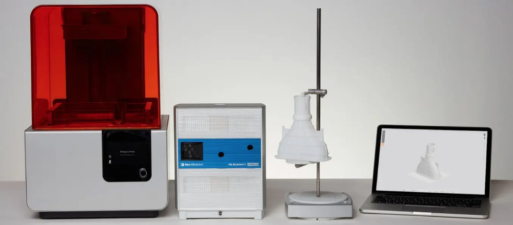
This simulation works best when you have full access to the subject and the ability to take an unlimited number of photos. The more photos, the better the lighting and the more correctly the photo shooting angles are chosen, the better and clearer the models will be.
With good observance of all the factors described above, the programs themselves find a way to combine photos to obtain a model, and human intervention is not required at all.
What should I use?
The choice of one of the three methods described above is based on what equipment you have, what size models you are going to scan, and access to the object - the ability to turn and inspect the model from all sides. If you need some kind of rough rule of thumb to start with, then use laser line scanning for small models (less than a human head), for medium-sized objects, structured-illuminated method, and for something large (for example, for scenery) the optimal choice there will be a simulation based on image scanning.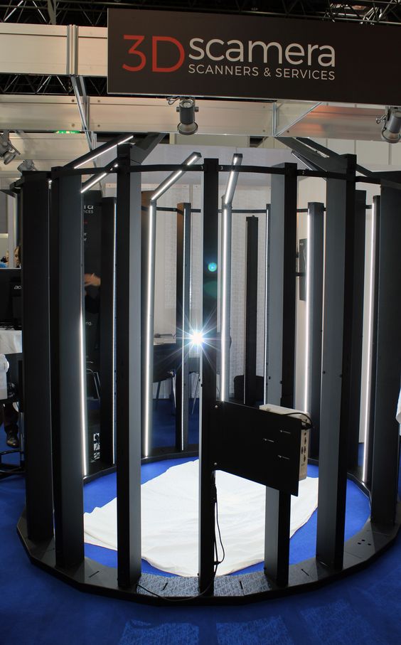
3D scanning of the product together with peel 3d
3D scanners
Reverse engineering
Experts recommend
Author: Ilya Krupennikov
Author: Ilya Krupennikov
1. Unboxing peel 3d 3D scanner | 2. Software installation and activation | 3. Request access to the client center | 4. Connecting a 3D scanner | 5. Calibration | 6. Part preparation | 7. Scan options | 8. Scan object | 9. Editing and saving a scan
Today we will talk about the basic principles of 3D scanning using the example of a professional manual peel 3d device. You will see how quickly and easily you can digitize a fairly complex object, even without experience with such equipment. peel 3d is a range of affordable portable reverse engineering 3D scanners designed and manufactured by market leader Creaform, a Canadian company. You can see the whole process described in the article in the video.
Need help or advice on 3D scanning, hardware and software selection? Contact our specialists and/or order a test scan for free!
Step 1. Unboxing the 3D scanner peel 3d
Let's start with unpacking. Place the package on the table with the label facing up and open it. You will see that all contents are in an antistatic case. First of all, this is the peel 2 3D scanner itself (it is equipped with an upper camera, a lower camera, a color camera and a white light projector), a lens cleaning cloth, a USB power cable that connects to the scanner, a universal automatic power supply, USB software -flash drive, two packs of 500 position markers, as well as standard adapters.
Beneath the foam insert is a calibration plate, which must be handled very carefully.
Step 2: Install and activate software
Now you need to install and activate the program. Take the USB key and run the installer. Then select the language of the program - one of the seven available. The program will be installed on your computer. After the installation is complete, find the "Calibration" folder on the USB key and select the calibration file. It is located in the "Configuration" folder. The license is activated in the same way. Find the "License" folder on the USB key and select the file to activate. Then click "OK". Now, most likely, the activation of the 3D scanner has been successfully completed.
Run the program. You will need to review the terms of service in their entirety and agree to them. Check the box next to "Do not show me again" (Do not show me again). Now you can start working with scans.
Step 3: Request access to the Client Center
It is best to create an account to which updates will come. The Customer Center has a link to request web access. Fill out and submit the form. Within 24-48 hours you will receive a confirmation email with login details (login and password). You can now log in to the customer support center.
Step 4 Connecting the
3D ScannerThe next step: connect the scanner to the computer. To do this, take the power supply, plug it into an outlet, and the other end of the cable into the connection on the end of the USB cable. Connect the USB cable to any USB port on your computer. The other end is with a connector with an arrow on it. The arrow must point up when you connect the cable to the scanner's rear connector.
A light will come on indicating that the connection has been established, and at the bottom of the screen you will see an indicator indicating that the scanner has been successfully connected.
Step 5 Calibrate
Take out the calibration plate. Do not touch the marks on its surface. Select the Calibrate icon in the program. Place the white square on top of the green square and then zoom out. The square will increase and eventually the automatic calibration will be completed.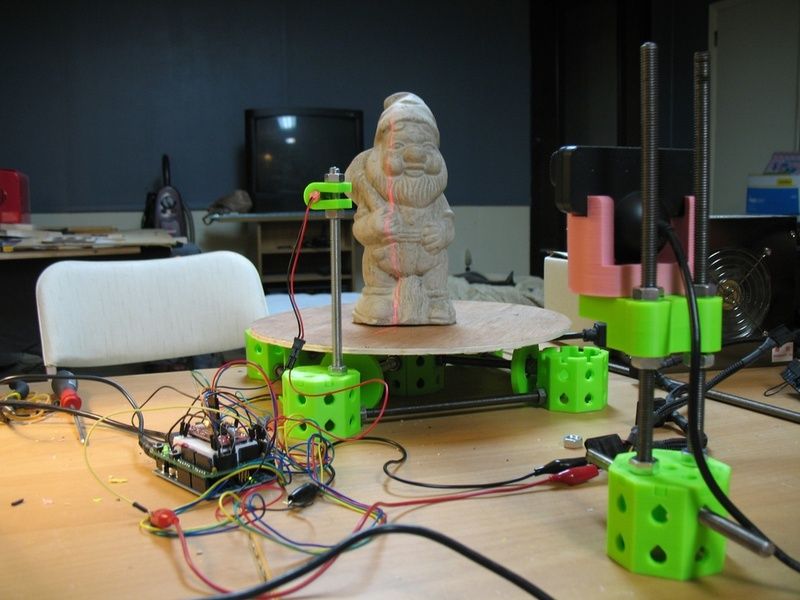 A confirmation will appear that the calibration was successful.
Step 6 Preparing Part
Now we need to prepare the part for scanning. A 3D scanner can determine its location relative to an object using marks, geometry, or even color. This part has a rather complex geometry. We need to provide good tracking, but there are shiny elements that are difficult for the scanner to digitize.
Shiny elements can be sprayed with a Matting Spray, allowing them to be scanned along with the rest in one session. You can also stick several position marks on the object, this will help scanning. The geometry of this part does not require marks, but we use them because it is recommended and allows you to rescan the object if some parts are missing.
Step 7Scan Options
Now let's configure the scan settings. Since the object is single color, we can turn off Texture Capture. The positioning parameters can be adjusted to a specific geometry, and the positioning status display can be left active to see possible interruptions in the scanning process.
We will demonstrate how to adjust the shutter manually if necessary. Automatic setting is fine for most cases, but you can choose to manually adjust the shutter, then point the scanner at an object, press and hold the shutter button, and the device will display the current shutter speed on the surface of the object. Gray color - insufficient exposure, yellow - the most suitable, red - too long.
You can use the slider to adjust the shutter speed to optimize the 3D scanning process. Set the resolution to one or two millimeters. You can always change it after scanning, it's not a fixed value. Now everything is ready for scanning.
Step 8Scan object
Click on Scan. Hold down the yellow button and, keeping an adequate distance (about thirty centimeters from the object), start the scanning process.
On the left in the photo you see a stripe. If it is green, you are at the correct distance. Yellow is too close, blue is too far.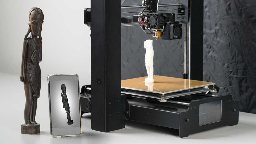
Start scanning. You need to go around the object to capture individual bumps and crevices and for the scanner to "see" every detail in its entirety. However, here it perfectly reads the geometry with one or two marks that we have pasted on the object.
Tracking may be interrupted. In this case, an alert will appear on the screen showing the positioning status. When tracking is interrupted, you can simply go back to a part with marks or a part you previously scanned and the 3D scanner will resume tracking so you can continue scanning. We have a rather complex object in front of us, but you can see that the device is tracking very well.
Step 9. Editing and saving the scan
We process and save the scan. Just click the "Scan" button again for further processing, which is usually very fast. Now you see the end result.
You may need to eliminate unnecessary geometry that you did not need to scan. To remove unwanted surfaces and noise, select the "Connect" (Connect), hold down the Ctrl key and select the main body of the scanned object.