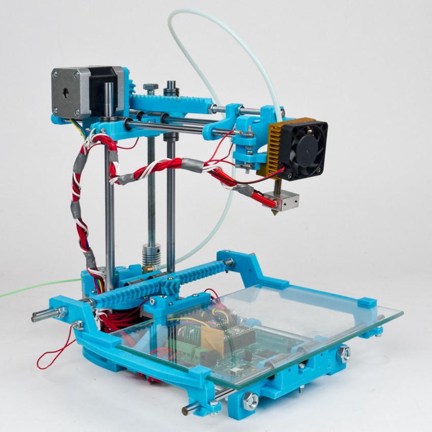
How a 3d printer is made
How Ultimaker 3D printers are manufactured
Our main production facility is based in Zaltbommel, the Netherlands. As an ISO 9001 certified production facility, we place a strong emphasis on quality. We use lean manufacturing methods in order to ensure efficient, high-quality production of every Ultimaker 3D printer that is delivered to our customers. Along the way, we also make use of some 3D printed manufacturing aids to streamline production.
Quality and efficiency across processes
Components that make up Ultimaker 3D printers are delivered to our inbound quality control department, where a sample from each shipment is measured and tested to ensure they reach our standards. Parts are mainly sourced from Europe, but some specifically manufactured parts, such as stepper motors, are sourced from China.
Axle shafts are one example: these are tested for consistency with a dial caliper. If the shaft is ‘out of round’ or bowed, a dial caliper will register it and the part will be rejected. If there are too many rejected parts in a sample, the entire shipment is returned.
An axle shaft is checked for quality with a dial gauge
After testing, shipments are sorted and stored. When parts are needed on the production floor, a centralized system will generate a picklist. Part pickers use a scanner to log each item as picked, and it is automatically deducted from the main inventory.
Raw components are stored in the warehouse until needed
Assembling an Ultimaker 3D printer begins with a set of panels that make up the frame. Each panel is populated with bearings, nuts, and inserts before assembly.
Each step in the manufacturing process is logged on a centralized system, which feeds back data on the ‘first time right’ of each production step. This helps to identify production bottlenecks that can be improved in order to keep efficiency at a maximum.
Panels are populated with hardware before assembly and inspection
An extendable arm on this driving tool ensures that each insert is driven completely perpendicular to the panel
Assembled frames must sit completely level on a flat surface and be free of any cosmetic defects.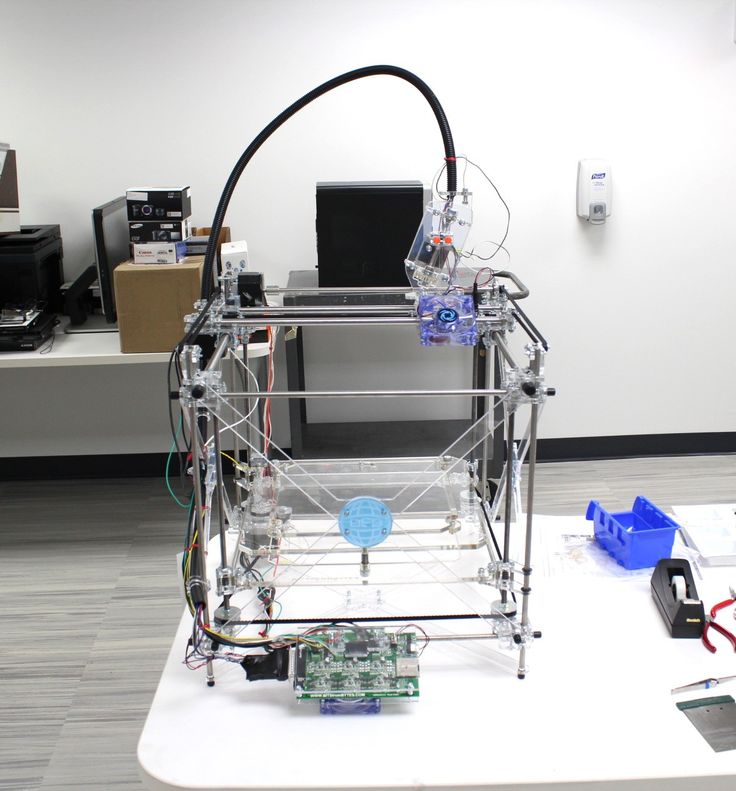 When approved, they proceed to the main production area, where they are populated with parts such as feeders, print heads, and heated beds. The main production area is completely ESD-safe in order to avoid damage to any internal electronic components.
One method we use to keep production efficient is poka-yoke – a method that minimizes human error. Each part that makes up a printer is placed in a foam inlay pocket that will only fit a specific part. Through this, workers can identify missing parts through a quick visual inspection. There is also less chance of confusing similar parts; different lengths of axle shaft, for example, will only fit in their designated pocket.
Foam inlays are stacked in crates in order of assembly, with the top layer first. All the parts in the top layer must be fitted into the printer before the next layer can start, so that assembly is smooth and uninterrupted.
Frames and parts are transported through the production area on a roller conveyor ready for assembly
A 3D printed brush holder makes applying grease to the Z screw more convenient
Ultimaker 3 print heads waiting to be fitted
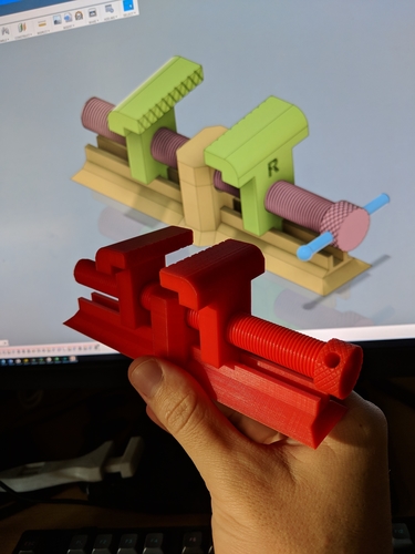
Around 400 sliding block assemblies are produced daily.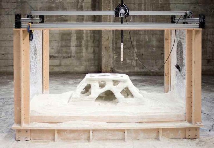 These consist of two separate plastic pieces that are clamped together over a sintered bushing, timing belt, and spring, before fitting into the printer to drive the print head. Producing these assemblies was once performed by hand, but with the help of a 3D printed jig fitted to a press, labor is dramatically easier and more productive.
Poka-yoke inlays also make keeping track of tools easier: a quick visual inspection will identify any missing tools. We use custom 3D printed manufacturing aids too – this drill holder increases worker convenience
Print core assembly and testing
Print cores are assembled by hand and then put in a press to be sealed. There are designated stations for AA, BB, and CC print cores, with a quality inspection stage at the end.
Ultimaker print cores are ready for quality checks
Tested for safety and performance
We take safety very seriously at Ultimaker. All of our printers are compliant with international safety standards and regulations. As the Ultimaker S5 has an integrated power supply, it must be tested for electrical safety through a process known as ‘hipot’ testing. This ensures it is properly electrically isolated and safe to use.
Hipot testing Ultimaker S5 3D printers
These yellow safety plugs are 3D printed. They were designed and manufactured in-house by our engineers to streamline the testing process
The safety plug has two functions – it keeps the power switch in the off position, and keeps the electrical socket occupied to indicate the 3D printer has not yet been tested
All printers are XY calibrated for AA-AA and AA-AB print core combinations, so that they can dual-extrude reliably out of the box. Wi-Fi and camera modules are also tested to ensure they reach customers in a fully-functional state.
Each printer is XY calibrated and runs print tests for a minimum of 45 minutes
Examples of successful and unsuccessful ‘minical’ prints indicate to workers what to fix if a printer doesn’t pass its print test. To show that it is properly configured, every Ultimaker shipped will contain a minical print, produced by the printer itself
With safety and performance tested and approved, printers are packaged and stored before shipping through our global sales and distribution network.
A finished Ultimaker S5 3D printer
Ready to print your next big idea?
The Ultimaker S5 is ready for serious manufacturing applications. You’ve seen how it’s produced, so why not discover what it can produce for you by clicking the link below.
Learn more about the Ultimaker S5
3D Printing: What It Is, How It Works and Examples
3D printers might seem like they're right out of a science fiction movie, but they're proving to be useful in a variety of industries. | Image: ShutterstockHow Do 3D Printers Work?
3D printing is part of the additive manufacturing family and uses similar methods to a traditional inkjet printer — albeit in 3D. Additive manufacturing describes the process of creating something in layers, adding material continuously until the final design is complete. This term most often refers to molding and 3D printing.
It takes a combination of top-of-the-line software, powder-like materials and precision tools to create a three-dimensional object from scratch. Below are a few of the main steps 3D printers take to bring ideas to life.
How Does a 3D Printer Work?
3D printers are related to additive manufacturing. 3D printers use computer-aided design to understand a design. When a design is ready, a material that can be dispensed through a hot nozzle or precision tool is printed layer by layer to create a three-dimensional object from scratch.
3D Modeling Software
The first step of any 3D printing process is 3D modeling. To maximize precision — and because 3D printers can’t magically guess what you want to print — all objects have to be designed in a 3D modeling software. Some designs are too intricate and detailed for traditional manufacturing methods. That’s where CAD software comes in.
Modeling allows printers to customize their product down to the tiniest detail. The 3D modeling software’s ability to allow for precision designs is why 3D printing is being hailed as a true game changer in many industries. This modeling software is especially important to an industry, like dentistry, where labs are using 3D software to design teeth aligners that precisely fit to the individual. It’s also vital to the space industry, where they use the software to design some of the most intricate parts of a rocketship.
3D PRINTERS USE MODELING AND SLICING SOFTWARE TO GUIDE THE PRINTER IN CREATING EACH OBJECT. Video: Digital Trends
Slicing the Model
Once a model is created, it’s time to “slice” it. Since 3D printers cannot conceptualize the concept of three dimensions, like humans, engineers need to slice the model into layers in order for the printer to create the final product.
Slicing software takes scans of each layer of a model and will tell the printer how to move in order to recreate that layer. Slicers also tell 3D printers where to “fill” a model. This fill gives a 3D printed object internal lattices and columns that help shape and strengthen the object. Once the model is sliced, it’s sent off to the 3D printer for the actual printing process.
The 3D Printing Process
When the modeling and slicing of a 3D object is completed, it’s time for the 3D printer to finally take over. The printer acts generally the same as a traditional inkjet printer in the direct 3D printing process, where a nozzle moves back and forth while dispensing a wax or plastic-like polymer layer-by-layer, waiting for that layer to dry, then adding the next level. It essentially adds hundreds or thousands of 2D prints on top of one another to make a three-dimensional object.
3D Printing Materials
There are a variety of different materials that a printer uses in order to recreate an object to the best of its abilities.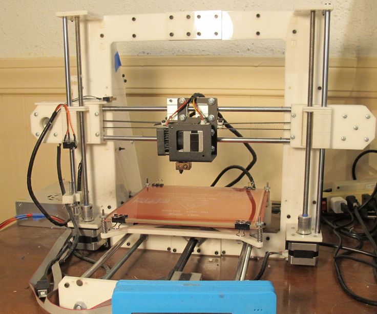 Here are some examples:
Acrylonitrile Butadiene Styrene (ABS)
Plastic material that is easy to shape and tough to break. The same material that LEGOs are made out of.
Carbon Fiber Filaments
Carbon fiber is used to create objects that need to be strong, but also extremely lightweight.
Conductive Filaments
These printable materials are still in the experimental stage and can be used for printing electric circuits without the need for wires. This is a useful material for wearable technology.
Flexible Filaments
Flexible filaments produce prints that are bendable, yet tough. These materials can be used to print anything from wristwatches to phone covers.
Metal Filament
Metal filaments are made of finely ground metals and polymer glue. They can come in steel, brass, bronze and copper in order to get the true look and feel of a metal object.
Wood Filament
These filaments contain finely ground wood powder mixed with polymer glue.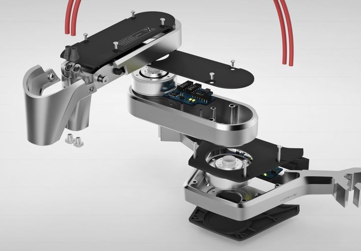 These are obviously used to print wooden-looking objects and can look like a lighter or darker wood depending on the temperature of the printer.
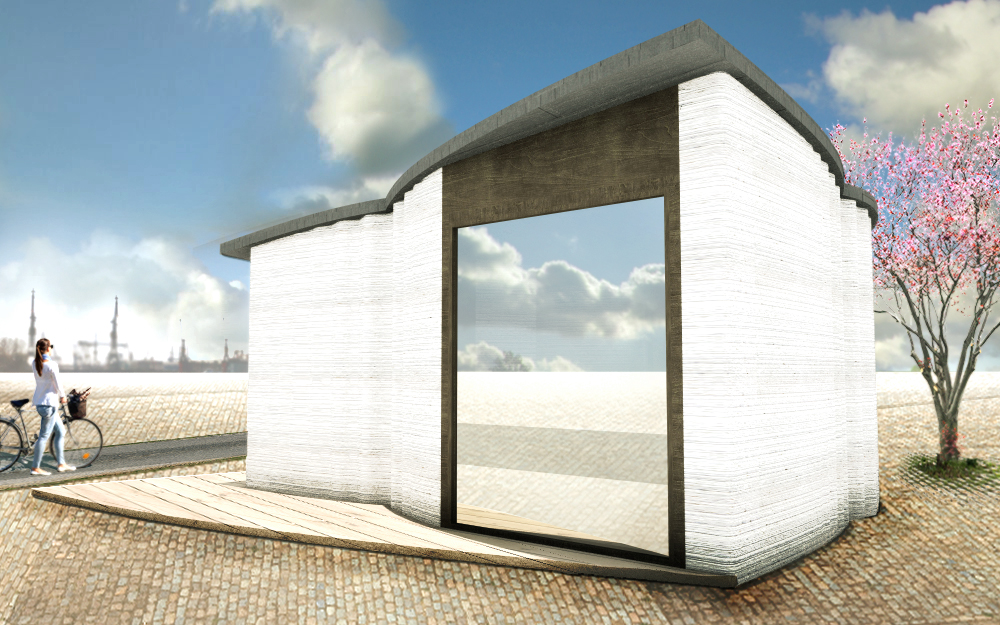
The 3D printing process takes anywhere from a few hours for really simple prints, like a box or a ball, to days or weeks for much larger detailed projects, like a full-sized home.
How Much Do 3D Printers Cost?
The cost of 3D printers vary based on the size, specialty and use. The cheapest 3D printers, for entry level hobbyists, typically range from $100 to $500. More advanced models can range between $300 and $5,000. Industrial 3D printers can cost up to $100,000.
3D Printing Processes and Techniques
here are also different types of 3D printers depending on the size, detail and scope of a project. Each different type of printer will vary slightly on how an object gets printed.
Fused Deposition Modeling (FDM)
FDM is probably the most widely used form of 3D printing. It’s incredibly useful for manufacturing prototypes and models with plastic.
Stereolithography (SLA) Technology
SLA is a fast prototyping printing type that is best suited for printing in intricate detail. The printer uses an ultraviolet laser to craft the objects within hours.
Digital Light Processing (DLP)
DLP is one of the oldest forms of 3D printing. DLP uses lamps to produce prints at higher speeds than SLA printing because the layers dry in seconds.
Continuous Liquid Interface Production (CLIP)
CLIP is amongst the faster processes that use Vat Photopolymerisation. The CLIP process utilizes Digital Light Synthesis technology to project a sequence of UV images across a cross-section of a 3D printed part, resulting in a precisely controlled curing process. The part is then baked in a thermal bath or oven, causing several chemical reactions that allow the part to harden.
Material Jetting
Material Jetting applies droplets of material through a small diameter nozzle layer-by-layer to build a platform, which becomes hardened by UV light.
Binder Jetting
Binder Jetting utilizes a powder base material layered evenly along with a liquid binder, which is applied through jet nozzles to act as an adhesive for the powder particles.
Fused Deposition Modeling (FDM)
FDM, also known as Fused Filament Fabrication (FFF), works by unwinding a plastic filament from a spool and flowing through a heated nozzle in horizontal and vertical directions, forming the object immediately as the melted material hardens.
Selective Laser Sintering (SLS)
A form of Powder Bed Fusion, SLS fuses small particles of powder together by use of a high-power laser to create a three-dimensional shape. The laser scans each layer on a powder bed and selectively fuses them, then lowering the powder bed by one thickness and repeating the process through completion.
Multi-Jet Fusion (MJF)
Another form of Powder Bed Fusion, MJF uses a sweeping arm to deposit powder and an inkjet-equipped arm to apply binder selectively on top. Next, a detailing agent is applied around the detailing agent for precision. Finally, thermal energy is applied to cause a chemical reaction. Direct Metal Laser Sintering (DMLS) also utilizes this same process but with metal powder specifically.
Sheet Lamination
Sheet Lamination binds material in sheets through external force and welds them together through layered ultrasonic welding. The sheets are then milled in a CNC machine to form the object’s shape.
Directed Energy Deposition
Directed Energy Deposition is common in the metal industry and operates by a 3D printing apparatus attached to a multi-axis robotic arm with a nozzle for applying metal powder. The powder is applied to a surface and energy source, which then melts the material to form a solid object.
Homemade metal 3D printer, but something went wrong / Sudo Null IT News
Hello everyone, my name is Sergey. In this article, we will talk about 3D printing with metal, more precisely, about my attempt to implement 3D printing with metal.
Very often, people who are interested in or engaged in any activity, no matter what, stumble upon something completely new and previously unknown to them, something that can help develop/improve their main activity. A similar situation happened to me.
Surfing the expanses of your Internet, I came across a wonderful technology for vacuum deposition of metals on various materials. On Habré there is an interesting article about this technology. In addition, on many other resources it was said that the evaporated metal moves towards the target in a straight line.
Many resources0003
And then I thought, what if I spray metal in the place I need, gradually increasing the thickness? I looked for information about whether someone did this - I did not find it.
Registered on a forum where sprayers gather together and began to disturb them with questions like: is it possible to build up a “film” with a thickness of 1 or more millimeters.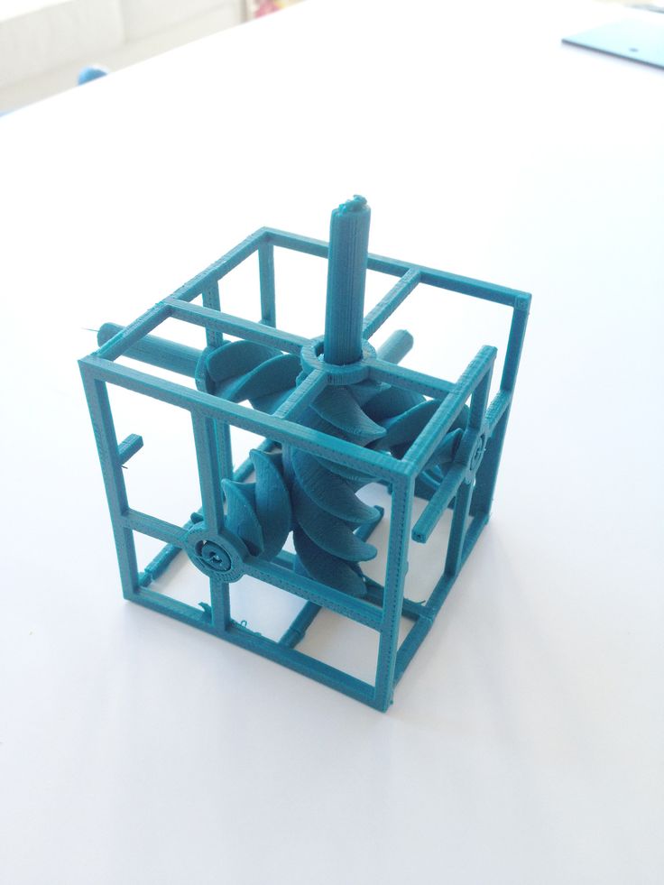 To which I caught a lot of misunderstanding what it was for, but received a positive answer.
General information received, you can begin to prepare for experiments.
It is known from various articles and documents that a vacuum of no more than 10⁻² Pa is needed. For comparison, the order of magnitude - the pressure that gives a household vacuum pump (Value and others) - about 4 Pa (measured value), i.e. pressure is 400 times greater than necessary. How to deal with it and what to do? To achieve low pressures, turbomolecular vacuum pumps are used, they work in parallel with the foreline pump and, literally by molecules, capture the remaining air from the chamber. The process is not fast. The pump looks like this.
We installed a pump, it pumps out air and everything seems to be fine, but how to find out the pressure? For this I chose an ionization vacuum gauge.
In fact, nothing else is needed, except for the chamber and evaporator. I did not find a ready-made affordable (in terms of finances) camera, therefore, I decided to make my own. It is of a small volume (about 8-10 liters) in order for the air to be pumped out faster. Usually, the chambers have a spherical shape, in my case it is, on the contrary, elongated, in order to be able to set the “target” (the place where the metal is deposited) at different distances from the evaporator. In addition, the camera has a lot of flanges for connecting all kinds of inputs/outputs and sensors. I modeled the camera in a well-known CAD program, drew drawings and transferred it to production.
Current leads and conductors I made from a brass bar and a brass rod, bought on the local market. (Juno, who is from St. Petersburg).
In the photo below, a tungsten boat is fixed between two conductors.
The bottom part looks like this. The photo shows the cooling tubes of the current leads. Subsequently, I abandoned them, due to the simplification of the system.
Assembling the camera did not take much effort and complexity.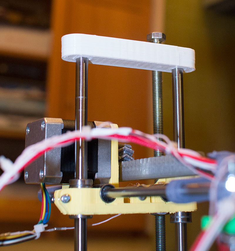 It is much more difficult to achieve vacuum retention in this chamber. To do this, I polished the flanges and all mating surfaces to avoid the slightest leakage through the rubber seal (in the photo below, I processed only the top flange).
As it turned out later, the weld is not airtight at all (meaning for low vacuum). I, out of inexperience, assumed that by pumping a pressure of 300 kPa into the chamber and immersing it in a bath of water, I would carefully find all the leaks and eliminate them. Yes, at the first stage I did just that, but the pressure in the chamber did not fall below 10-2 Pa, there were leaks. Interestingly, before the start of the test, at a pressure in the chamber of 300 kPa, bubbles emerged from the welds with an intensity of approximately 1 bubble (diameter 2-3 mm) in 30-40 seconds. And those were big losses that I eliminated. But what to do with minimal vacuum losses that cannot be tracked in "kitchen" conditions?
The solution was close. To do this, all you need is a mass spectrometer.
The idea is simple – the investigated chamber or container is connected to the vacuum chamber of the spectrometer. Air is pumped out, on the graph they look for extraneous peaks of any gases. After that, helium is supplied locally, to the places of possible leakage. It is helium, because its penetrating power is higher and the helium peak can be easily tracked on the spectrum. As soon as helium enters the chamber through a micro-hole, it is immediately visible on the spectrum.
I drove twice and looked for leaks twice. Now the chamber with the installed pump is hermetic and it is possible to carry out experiments further, having previously assembled all the components of the system on the rack.
General view of the incredible installation.
Starting up the plant and checking it comes down to maintaining the lowest possible pressure. The foreline pump is started first.
The pressure after the operation of the foreline pump can be seen in the picture below.
After the pressure is established (does not change). You can launch "heavy artillery" - a turbomolecular pump. It reduces the pressure by another 3 orders of magnitude.
The time has come for experiments, what I have been going for so long and what I have been waiting for so long.
First experiment.
Place a small amount of silver into the boat fixed between the conductors. Above the boat I install a steam conduit - a soldered tin cylinder, which, as I thought, should limit the spread of metal through the chamber. Above the steam conduit there is a lid with a hole of 2 mm, behind the lid there is a target on which the metal should condense. It is a pity that there are no photos left, but the vacuum chamber was completely dusty. There was not a single place where there was no applied layer of metal. In the photo below, it’s not a different planet at all, but silver sprayed onto the inner surface of the wall.
Second experiment.
I thought it was because of the large gaps between the boat and the steam line. The solution was born immediately and quickly. I took two boats and combined them so that a shell was obtained. I placed silver inside, and cut a hole with a diameter of 2 mm in the upper half.
And he began to heat up the whole thing. But, I did not take into account the rigidity of the boats and the rigidity of the current leads. The shells parted a little and a gap formed between them, through which steam also flew in all directions.
As a result - spraying in the entire volume of the chamber. In the photo below there is a viewing window, the boat in which was slightly above half, but the window was completely dusty.
Third experiment.
After a little thought and grief, I thought that the container with the evaporated metal should be airtight and with only one outlet, but how and what to make it. From tungsten - very expensive and difficult to process.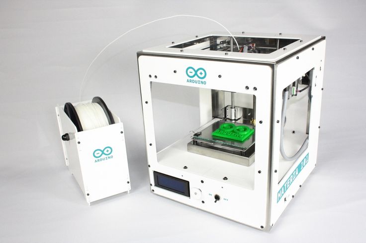 The way out has been found! Graphite is an excellent material for making a crucible, let's call it that. On the ad site, I found an ad for the sale of graphite bars from the contact whiskers of a trolleybus, cut out a bar with a hole in the center and made a cover for it. In the photo below - just a bar with a hole for the material (without a cover).
And in this photo already in the chamber with the lid installed (the hole in the lid is 1 mm in diameter).
Under the spoiler are a few photos with a short period of time, from which you can see how dusty the viewing window is.
Loss of transparency
It is obvious that in this case, too, there was no success, to my great regret. All three experiments were carried out with a gradual increase in temperature from the state when evaporation does not occur.
A small video in which the information is presented in a slightly different way, in a different form and volume.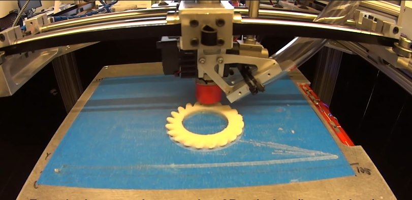
Video link
www.youtube.com/watch?v=4yWQOWIG1qw
Unfortunately, it was not possible to get what was intended, but, on the other hand, invaluable experience was gained in the design and manufacture of vacuum equipment. Most of this experience I have shared with you and I would be very grateful if you express your opinion on this issue.
Thank you all and good luck.
3D printing for dummies or "what is a 3D printer?"
- 1 3D printing term
- 2 3D printing methods
- 2.1 Extrusion printing
- 2.2 Melting, sintering or gluing
- 2.3 Stereolithography
- 2.4 Lamination
- 3 Fused Deposition Printing (FDM)
- 3.1 Consumables
- 3.2 Extruder
- 3.3 Working platform
- 3.
 4 Positioners
 - 3.5 Control
- 3.6 Varieties of FDM printers
- 4 Laser Stereolithography (SLA)
- 4.1 Lasers and projectors
- 4.2 Cuvette and resin
- 4.3 Varieties of Stereolithography Printers
The term 3D printing
The term 3D printing has several synonyms, one of which quite briefly and accurately characterizes the essence of the process - "additive manufacturing", that is, production by adding material. The term was not coined by chance, because this is the main difference between multiple 3D printing technologies and the usual methods of industrial production, which in turn received the name "subtractive technologies", that is, "subtractive". If during milling, grinding, cutting and other similar procedures, excess material is removed from the workpiece, then in the case of additive manufacturing, material is gradually added until a solid model is obtained.
Soon 3D printing will even be tested on the International Space Station
Strictly speaking, many traditional methods could be classified as "additive" in the broad sense of the word - for example, casting or riveting. However, it should be borne in mind that in these cases, either the consumption of materials is required for the manufacture of specific tools used in the production of specific parts (as in the case of casting), or the whole process is reduced to joining ready-made parts (welding, riveting, etc.). In order for the technology to be classified as “3D printing”, it is necessary to build the final product from raw materials, not blanks, and the formation of objects must be arbitrary - that is, without the use of forms. The latter means that additive manufacturing requires a software component. Roughly speaking, additive manufacturing requires computer control so that the shape of final products can be determined by building digital models. It was this factor that delayed the widespread adoption of 3D printing until the moment when numerical control and 3D design became widely available and highly productive.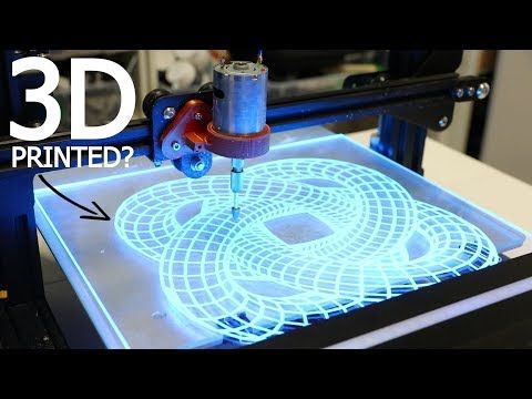
3D printing techniques
3D printing technologies are numerous, and there are even more names for them due to patent restrictions. However, you can try to divide technologies into main areas:
Extrusion printing
This includes methods such as deposition fusion (FDM) and multi-jet printing (MJM). This method is based on the extrusion (extrusion) of consumables with the sequential formation of the finished product. As a rule, consumables consist of thermoplastics or composite materials based on them.
Melting, sintering or bonding
This approach is based on bonding powdered material together. Formation is done in different ways. The simplest is gluing, as is the case with 3D inkjet printing (3DP). Such printers deposit thin layers of powder onto the build platform, which are then selectively bonded with a binder. Powders can be made up of virtually any material that can be ground to a powder—plastic, wood, metal.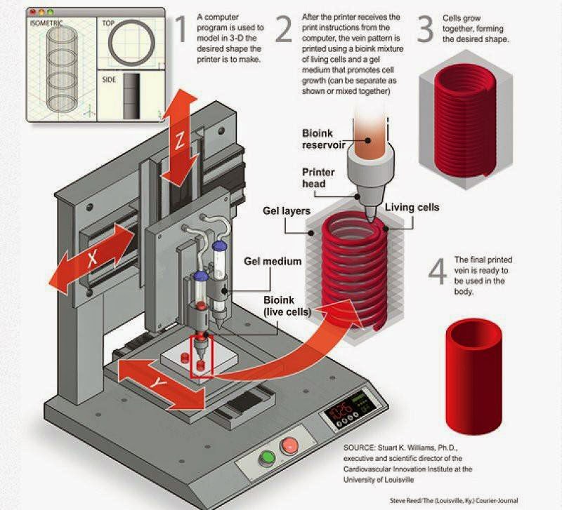
This model of James Bond's Aston Martin was successfully printed on a Voxeljet SLS printer and blown up just as successfully during the filming of Skyfall instead of the expensive original
sintering (SLS and DMLS) and smelting (SLM), which allow you to create all-metal parts. As with 3D inkjet printing, these devices apply thin layers of powder, but the material is not glued together, but sintered or melted using a laser. Laser sintering (SLS) is used to work with both plastic and metal powders, although metal pellets usually have a more fusible shell, and after printing they are additionally sintered in special ovens. DMLS is a variant of SLS installations with more powerful lasers that allow sintering metal powders directly without additives. SLM printers provide not just sintering of particles, but their complete melting, which allows you to create monolithic models that do not suffer from the relative fragility caused by the porosity of the structure.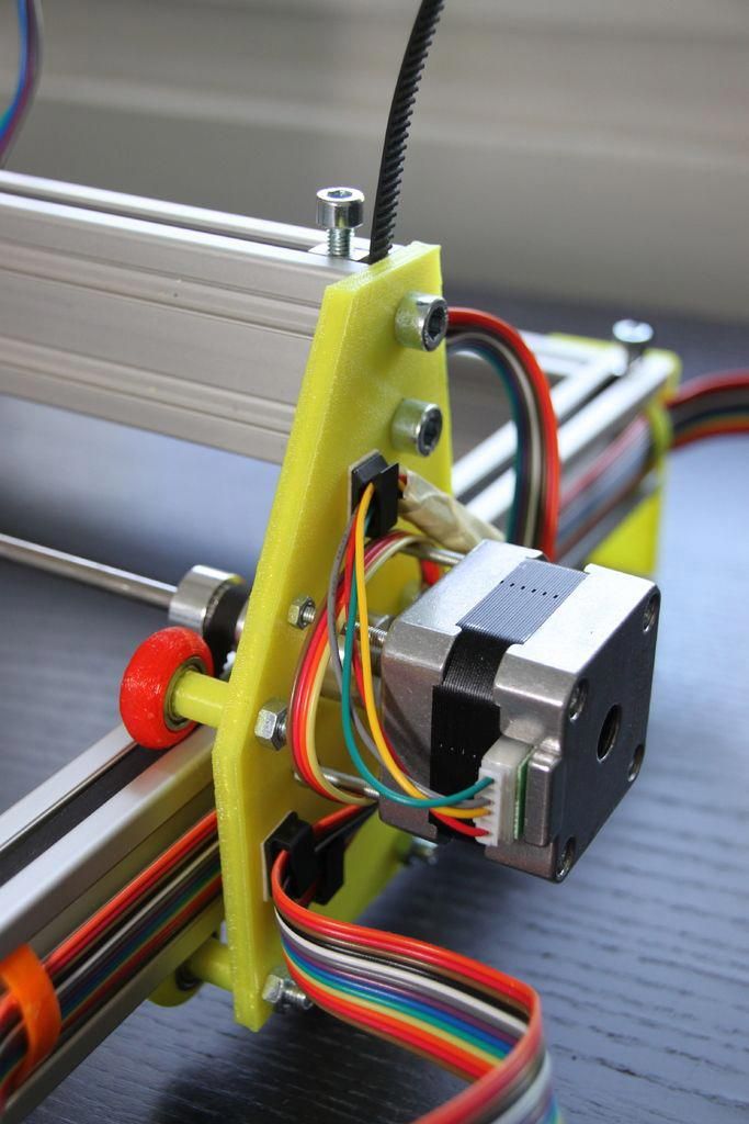 As a rule, printers for working with metal powders are equipped with vacuum working chambers, or they replace air with inert gases. Such a complication of the design is caused by the need to work with metals and alloys subject to oxidation - for example, with titanium.
Stereolithography
How an SLA printer works
Stereolithography printers use special liquid materials called "photopolymer resins". The term "photopolymerization" refers to the ability of a material to harden when exposed to light. As a rule, such materials react to ultraviolet irradiation.
Resin is poured into a special container with a movable platform, which is installed in a position near the surface of the liquid. The layer of resin covering the platform corresponds to one layer of the digital model. Then a thin layer of resin is processed by a laser beam, hardening at the points of contact. At the end of illumination, the platform together with the finished layer is immersed to the thickness of the next layer, and illumination is performed again.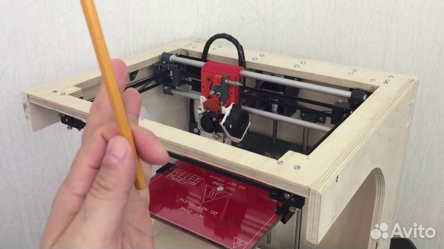
Lamination
Laminating (LOM) 3D printers workflow
Some 3D printers build models using sheet materials - paper, foil, plastic film.
Layers of material are glued on top of each other and cut along the contours of the digital model using a laser or a blade.
These machines are well suited for prototyping and can use very cheap consumables, including regular office paper. However, the complexity and noise of these printers, coupled with the limitations of the models they produce, limit their popularity.
Fused deposition modeling (FDM) and laser stereolithography (SLA) have become the most popular 3D printing methods used in the home and office.
Let's take a closer look at these technologies.
Fused Deposition Printing (FDM)
FDM is perhaps the simplest and most affordable 3D construction method, which makes it very popular.
High demand for FDM printers is driving device and consumable prices down rapidly, along with technology advances towards ease of use and improved reliability.
Consumables
ABS filament spool and finished model
FDM printers are designed to print with thermoplastics, which are usually supplied as thin filaments wound on spools. The range of "clean" plastics is very wide. One of the most popular materials is polylactide or "PLA plastic". This material is made from corn or sugar cane, which makes it non-toxic and environmentally friendly, but makes it relatively short-lived. ABS plastic, on the other hand, is very durable and wear-resistant, although it is susceptible to direct sunlight and can release small amounts of harmful fumes when heated. Many plastic items that we use on a daily basis are made from this material: housings for household appliances, plumbing fixtures, plastic cards, toys, etc.
In addition to PLA and ABS, printing is possible with nylon, polycarbonate, polyethylene and many other thermoplastics that are widely used in modern industry.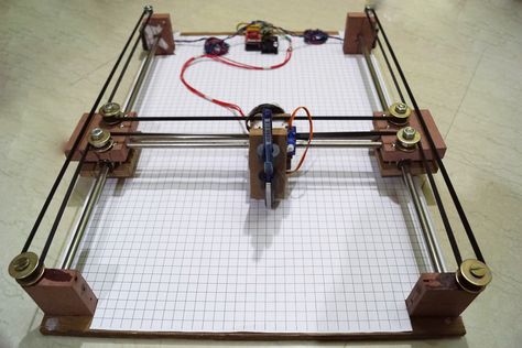 More exotic materials are also possible, such as polyvinyl alcohol, known as "PVA plastic". This material dissolves in water, which makes it very useful for printing complex geometric patterns. But more on that below.
Model made from Laywoo-D3. Changing the extrusion temperature allows you to achieve different shades and simulate annual rings
It is not necessary to print with homogeneous plastics. It is also possible to use composite materials imitating wood, metals, stone. Such materials use all the same thermoplastics, but with impurities of non-plastic materials.
So, Laywoo-D3 consists partly of natural wood dust, which allows you to print "wooden" products, including furniture.
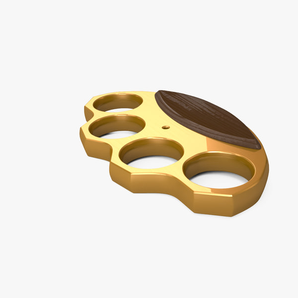
The material called BronzeFill is filled with real bronze, and models made from it can be ground and polished, achieving a high similarity to products made from pure bronze.
One has only to remember that thermoplastics serve as a binding element in composite materials - they determine the thresholds of strength, thermal stability and other physical and chemical properties of finished models.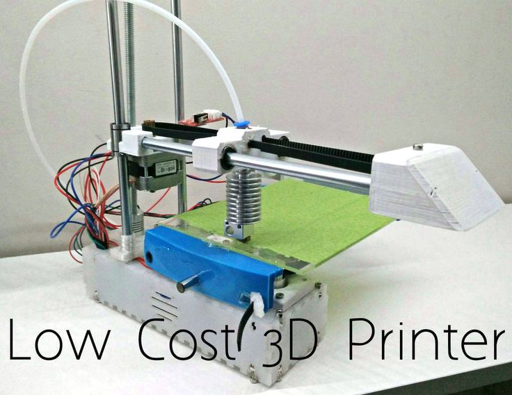
Extruder
Extruder - FDM print head. Strictly speaking, this is not entirely true, because the head consists of several parts, of which only the feed mechanism is directly "extruder". However, by tradition, the term "extruder" is commonly used as a synonym for the entire print assembly.
FDM extruder general design
The extruder is designed for melting and applying thermoplastic thread. The first component is the thread feed mechanism, which consists of rollers and gears driven by an electric motor. The mechanism feeds the thread into a special heated metal tube with a small diameter nozzle, called a "hot end" or simply a "nozzle". The same mechanism is used to remove the thread if a change of material is needed.
The hot end is used to heat and melt the thread fed by the puller. As a rule, nozzles are made from brass or aluminum, although more heat-resistant, but also more expensive materials can be used. For printing with the most popular plastics, a brass nozzle is quite enough. The “nozzle” itself is attached to the end of the tube with a threaded connection and can be replaced with a new one in case of wear or if a change in diameter is necessary. The nozzle diameter determines the thickness of the molten filament and, as a result, affects the print resolution. The heating of the hot end is controlled by a thermistor. Temperature control is very important, because when the material is overheated, pyrolysis can occur, that is, the decomposition of plastic, which contributes both to the loss of the properties of the material itself and to clogging of the nozzle.
PrintBox3D One FDM Printer Extruder
In order to prevent the filament from melting too early, the top of the hot end is cooled by heatsinks and fans. This point is of great importance, since thermoplastics that pass the glass transition temperature significantly expand in volume and increase the friction of the material with the walls of the hot end.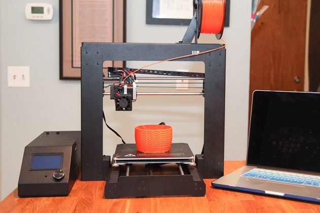 If the length of such a section is too long, the pulling mechanism may not have enough strength to push the thread.
The number of extruders may vary depending on the purpose of the 3D printer. The simplest options use a single printhead. The dual extruder greatly expands the capabilities of the device, allowing you to print one model in two different colors, as well as using different materials. The last point is important when building complex models with overhanging structural elements: FDM printers cannot print “over the air”, since the applied layers require support. In the case of hinged elements, temporary support structures have to be printed, which are removed after printing is completed. The removal process is fraught with damage to the model itself and requires accuracy. In addition, if the model has a complex structure with internal cavities that are difficult to access, building conventional supports may not be practical due to the difficulty in removing excess material.
Finished model with PVA supports (white) before and after washing
In such cases, the same water-soluble polyvinyl alcohol (PVA) comes in handy. Using a dual extruder, you can build a model from waterproof thermoplastic using PVA to create supports.
After printing, PVA can be simply dissolved in water and a complex product of perfect quality can be obtained.
Some FDM printers can use three or even four extruders.
Work platform
Heated platform covered with removable glass work table
Models are built on a special platform, often equipped with heating elements. Preheating is required for a wide range of plastics, including the popular ABS, which are subject to a high degree of shrinkage when cooled. The rapid loss of volume by cold coats compared to freshly applied material can lead to model distortion or delamination. The heating of the platform makes it possible to significantly equalize the temperature gradient between the upper and lower layers.
Heating is not recommended for some materials. A typical example is PLA plastic, which requires a fairly long time to harden. Heating PLA can lead to deformation of the lower layers under the weight of the upper ones. When working with PLA, measures are usually taken not to heat up, but to cool the model. Such printers have characteristic open cases and additional fans blowing fresh layers of the model.
Calibration screw for work platform covered with blue masking tape
The platform needs to be calibrated before printing to ensure that the nozzle does not hit the applied layers and move too far causing air-to-air printing resulting in plastic vermicelli. The calibration process can be either manual or automatic. In manual mode, calibration is performed by positioning the nozzle at different points on the platform and adjusting the platform inclination using the support screws to achieve the optimal distance between the surface and the nozzle.
As a rule, platforms are equipped with an additional element - a removable table. This design simplifies the cleaning of the working surface and facilitates the removal of the finished model. Stages are made from various materials, including aluminum, acrylic, glass, etc. The choice of material for the manufacture of the stage depends on the presence of heating and consumables for which the printer is optimized.
For a better adhesion of the first layer of the model to the surface of the table, additional tools are often used, including polyimide film, glue and even hairspray! But the most popular tool is inexpensive, but effective masking tape. Some manufacturers make perforated tables that hold the model well but are difficult to clean. In general, the expediency of applying additional funds to the table depends on the consumable material and the material of the table itself.
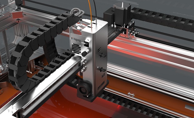
Positioning mechanisms
Scheme of operation of positioning mechanisms
Of course, the print head must move relative to the working platform, and unlike conventional office printers, positioning must be carried out not in two, but in three planes, including height adjustment.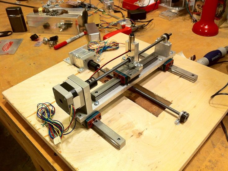
Positioning pattern may vary. The simplest and most common option involves mounting the print head on perpendicular guides driven by stepper motors and providing positioning along the X and Y axes.
Vertical positioning is carried out by moving the working platform.
On the other hand, it is possible to move the extruder in one plane and the platforms in two.
SeemeCNC ORION Delta Printer
One option that is gaining popularity is the delta coordinate system.
Such devices are called "delta robots" in the industry.
In delta printers, the printhead is suspended on three manipulators, each of which moves along a vertical rail.
The synchronous symmetrical movement of the manipulators allows you to change the height of the extruder above the platform, and the asymmetric movement causes the head to move in the horizontal plane.
A variant of this system is the reverse delta design, where the extruder is fixed to the ceiling of the working chamber, and the platform moves on three support arms.
Delta printers have a cylindrical build area, and their design makes it easy to increase the height of the working area with minimal design changes by extending the rails.
In the end, everything depends on the decision of the designers, but the fundamental principle does not change.
Control
Typical Arduino-based controller with add-on modules
FDM printer operation, including nozzle and platform temperature, filament feed rate, and stepper motors for positioning the extruder, is controlled by fairly simple electronic controllers. Most controllers are based on the Arduino platform, which has an open architecture.
The programming language used by printers is called G-code (G-Code) and consists of a list of commands executed in turn by the 3D printer systems. G-code is compiled by programs called "slicers" - standard 3D printer software that combines some of the features of graphics editors with the ability to set print options through a graphical interface.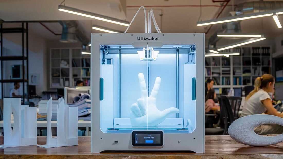 The choice of slicer depends on the printer model. RepRap printers use open source slicers such as Skeinforge, Replicator G and Repetier-Host. Some companies make printers that require proprietary software.
Program code for printing is generated using slicers
As an example, we can mention Cube printers from 3D Systems. There are companies that offer proprietary software but allow third-party software, as is the case with the latest generation of MakerBot 3D printers.
Slicers are not intended for 3D design per se. This task is done with CAD editors and requires some 3D design skills. Although beginners should not despair: digital models of a wide variety of designs are offered on many sites, often even for free. Finally, some companies and individuals offer 3D design services for custom printing.
Finally, 3D printers can be used in conjunction with 3D scanners to automate the process of digitizing objects. Many of these devices are designed specifically to work with 3D printers.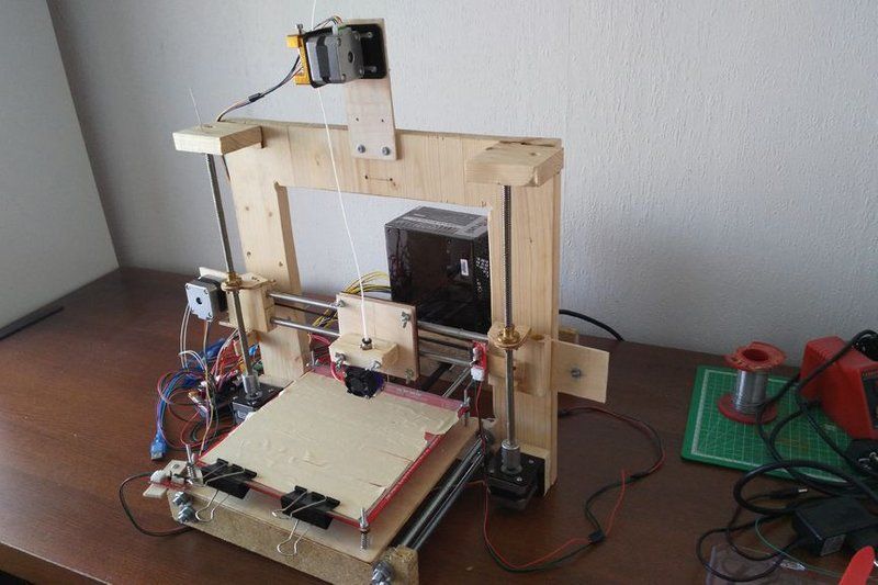 Notable examples include the 3D Systems Sense handheld scanner and the MakerBot Digitizer handheld desktop scanner.
MakerBot Replicator 5th Generation FDM Printer with built-in control module on the top of the frame
The user interface of a 3D printer can consist of a simple USB port for connecting to a personal computer. In such cases, the device is actually controlled by the slicer.
The disadvantage of this simplification is a rather high probability of printing failure when the computer freezes or slows down.
A more advanced option includes an internal memory or memory card interface to make the process standalone.
These models are equipped with control modules that allow you to adjust many print parameters (such as print speed or extrusion temperature). The module may include a small LCD display or even a mini-tablet.
Varieties of FDM printers
Professional Stratasys Fortus 360mc FDM printer that allows printing with nylon
FDM printers are very, very diverse, ranging from the simplest home-made RepRap printers to industrial installations capable of printing large-sized objects.
Stratasys, founded by Scott Crump, the inventor of FDM technology, is a leader in the production of industrial installations.
You can build the simplest FDM printers yourself. Such devices are called RepRap, where "Rep" indicates the possibility of "replication", that is, self-reproduction.
RepRap printers can be used to print custom built plastic parts.
Controller, rails, belts, motors and other components can be easily purchased separately.
Of course, assembling such a device on your own requires serious technical and even engineering skills.
Some manufacturers make it easy by selling DIY kits, but these kits still require a good understanding of the technology. RepRap Printers
And, despite their "homemade nature", RepRap printers are quite capable of producing models with the quality of expensive branded counterparts.
Ordinary users who do not want to delve into the intricacies of the process, but require only a convenient device for household use, can purchase a ready-made FDM printer.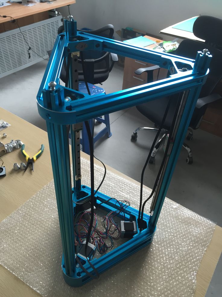
Many companies are focusing on the development of the consumer market segment, offering 3D printers for sale that are ready to print “right out of the box” and do not require serious computer skills.
3D Systems Cube consumer 3D printer
The most famous example of a consumer 3D printer is the 3D Systems Cube.
While it doesn't boast a huge build area, ultra-fast print speeds, or superb build quality, it's easy to use, affordable, and safe: This printer has received the necessary certification to be used even by children.
Mankati FDM printer demonstration: http://youtu.be/51rypJIK4y0
Laser Stereolithography (SLA)
Stereolithographic 3D printers are widely used in dental prosthetics
Stereolithographic printers are the second most popular and widespread after FDM printers.
These units deliver exceptional print quality.
The resolution of some SLA printers is measured in a matter of microns - it is not surprising that these devices quickly won the love of jewelers and dentists.
The software side of laser stereolithography is almost identical to FDM printing, so we will not repeat ourselves and will only touch on the distinctive features of the technology.
Lasers and projectors
Projector illumination of a photopolymer model using Kudo3D Titan DLP printer as an example
The cost of stereolithography printers is rapidly declining due to growing competition due to high demand and the use of new technologies that reduce the cost of construction.
Although the technology is generically referred to as "laser" stereolithography, most recent developments use UV LED projectors for the most part.
Projectors are cheaper and more reliable than lasers, do not require the use of delicate mirrors to deflect the laser beam, and have higher performance. The latter is explained by the fact that the contour of the whole layer is illuminated as a whole, and not sequentially, point by point, as is the case with laser options.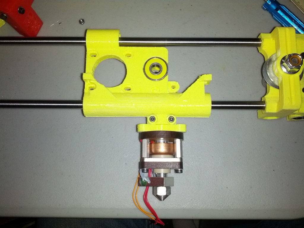 This variant of the technology is called projection stereolithography, "DLP-SLA" or simply "DLP". However, both options are currently common - both laser and projector versions.
Cuvette and resin
Photopolymer resin is poured into a cuvette
A photopolymer resin that looks like epoxy is used as consumables for stereolithographic printers. Resins can have a variety of characteristics, but they all share one key feature for 3D printing applications: these materials harden when exposed to ultraviolet light. Hence, in fact, the name "photopolymer".
When polymerized, resins can have a wide variety of physical characteristics. Some resins are like rubber, others are hard plastics like ABS. You can choose different colors and degrees of transparency. The main disadvantage of resins and SLA printing in general is the cost of consumables, which significantly exceeds the cost of thermoplastics.
On the other hand, stereolithographic printers are mainly used by jewelers and dentists who do not need to build large parts but appreciate the savings from fast and accurate prototyping.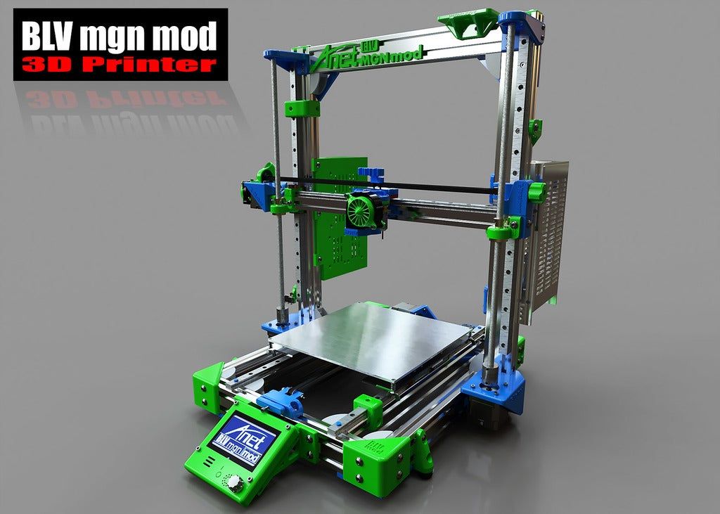 Thus, SLA printers and consumables pay for themselves very quickly.
An example of a model printed on a laser stereolithographic 3D printer
Resin is poured into a cuvette, which can be equipped with a lowering platform. In this case, the printer uses a leveling device to flatten the thin layer of resin covering the platform just prior to irradiation. As the model is being made, the platform, together with the finished layers, is “embedded” in the resin. Upon completion of printing, the model is removed from the cuvette, treated with a special solution to remove liquid resin residues and placed in an ultraviolet oven, where the final illumination of the model is performed.
Some SLA and DLP printers work in an “inverted” way: the model is not immersed in the consumable, but “pulled” out of it, while the laser or projector is placed under the cuvette, and not above it. This approach eliminates the need to level the surface after each exposure, but requires the use of a cuvette made of a material transparent to ultraviolet light, such as quartz glass.
The accuracy of stereolithographic printers is extremely high. For comparison, the standard for vertical resolution for FDM printers is considered to be 100 microns, and some variants of SLA printers allow you to apply layers as thin as 15 microns. But this is not the limit. The problem, rather, is not so much in the accuracy of lasers, but in the speed of the process: the higher the resolution, the lower the print speed. The use of digital projectors allows you to significantly speed up the process, because each layer is illuminated entirely. As a result, some DLP printer manufacturers claim to be able to print with a vertical resolution of one micron!
Video from CES 2013 showing Formlabs Form1 stereolithography 3D printer in action: http://youtu.be/IjaUasw64VE
Stereolithography Printer Options
Formlabs Form1 Desktop Stereolithography Printer
As with FDM printers, SLA printers come in a wide range in terms of size, features and cost.