G code viewer 3d printer
3/sec Show non-extrusion moves Show retracts and restarts Move model to the center of the grid Show different speeds with different colors Emulate extrusion width Render lines slightly transparent Show +1 layer
GCode analyzer options
These require re-analyzing file:
Sort layers by Z
Hide empty layers
Show GCode in GCode tab (memory intensive!)
Printer Info
Plastic diameter: Plastic type: ABS PLA Nozzle size: Volumetric E Printer hourly cost: Filament price(per gram):
Error Analysis
Run analysis
Render error analysis results
- 2D
- 3D
- GCode
- About
gCodeViewer is a visual GCode visualizer, viewer and analyzer in your own browser! It works on any OS in almost any modern browser (chrome, ff, safari 6, opera, ie10 should work too). All you need to do - is drag your *.gcode file to the designated zone.
Current features include:
- Visualize GCode in 2D, layer by layer
- Show retracts and restarts
- Show print/move/retract speeds
- Display only part of layer, animate sequence of layer printing
- Show two layers simultaneously so you can check overhangs
- Adjust line width to simulate print more closely
- Gcode viewer will try to parse nozzle and filament diameters from gcode, but it may fail to do so. In that case you will need to set it manually in 'Printer Info' tab
- Analyze GCode
- Print time, amount of plastic used, layer height, etc.
 for whole file and for single layer
 - Reference visualized part to GCode file (i.e. select a certain part of 2d visualization, switch to GCode view - it will highlight list of lines responsible for visualized piece)
- Print time, amount of plastic used, layer height, etc.
- Multiplatform, available online (but works offline too), works locally (doesn't upload you g-code anywhere or download anything but application itself)
- 3D visualization (I don't know what for, it's dull and useless.. need to rewrite it from scratch)
- And yeah, it's slow, memory hungry and only supports modern browsers
- Totally open source so you can use it as you like
All sources are available at https://github.com/hudbrog/gCodeViewer
If you find any bugs or have feature requests - don't hesitate to post them to https://github. com/hudbrog/gCodeViewer/issues
And I would appreciate if you like it on Thingiverse page: http://www.thingiverse.com/thing:35248
PrusaSlicer G-code viewer | Prusa Knowledge Base
Relevant for
:
Plus 1.75 mmMK2.5MK2.5SMK3MK3SMMU1MMU2SSL1MINIMK2SMK3S+MINI+SL1S
Last updated
5 months ago
This article is also available in following languages:
Standalone PrusaSlicer G-code Viewer is a lightweight application, which you can use to quickly preview G-codes from all popular slicers. Its behavior is identical to the preview in PrusaSlicer (the same code is used), however, you can load an external G-code file.
Supported slicers
We currently parse, and up to some level interpret, G-code from:
- PrusaSlicer
- Slic3r and Slic3rPE
- CURA
- ideaMaker
- Simplify3D
- Craftware
- KISSSlicer
PrusaSlicer Standalone G-code Viewer tries hard to estimate the extrusion widths, layer heights, extrusion types, types of moves, layers, etc. from the G-code generated by various slicers. The G-code itself does not contain all the information mentioned above, thus the G-code is usually augmented with slicer specific comments. We try to get as much data as possible, but some parts might still get marked as unknown.
PrusaSlicer version 2.3 and newer augments the G-code with comments ";TYPE:", ";HEIGHT:", ";LAYER_CHANGE", ";COLOR_CHANGE", ";PAUSE_PRINT" and ";CUSTOM_GCODE". G-code generated by older PrusaSlicer which does not contain these new annotations will still be displayed, but the extrusion widths or extrusion types may not be shown reliably.
G-code generated with other slicers will most likely still load correctly, but some features, such as the print time analysis by feature might be unavailable.
Associate with .gcode file extension
If you associate the .gcode file extension with the G-code viewer, you'll be able to launch it simply by opening the file (double-clicking on it or pressing Enter).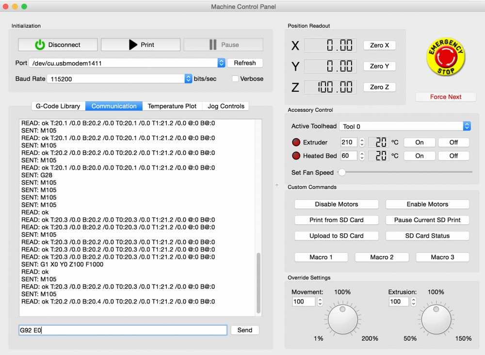 You can do so by enabling Configuration - Preferences - Associate .gcode files to PrusaSlicer G-code Viewer.
Alternatively, you associate the file extension using your operating system tools.
Windows
- Right-click any G-code file
- Select Open with - Choose default program... - PrusaSlicer G-code Viewer
- Click More at the bottom
- Tick Always use this app
macOS
- Select any G-code file in the Finder and choose File > Get Info
- In the Open With section, select PrusaSlicer G-code Viewer
- Click Change All and confirm
Ubuntu
- Select any G-code file
- Right-click the file and select Properties
- Select the Open With tab
- Select PrusaSlicer G-code Viewer and click Set as default.

The process is similar on other Linux distributions.
Features
The stand-alone G-Code Viewer shows names of used Printer/Print settings/Filament.
Once the final G-code is available after slicing, a new horizontal slider shows up, limiting visualization of extrusions and travel by time thus allowing simulation of the print in time. By default the new horizontal slider limits visualization of the last layer selected by the vertical toolbar. Alternatively the horizontal slider limits the extrusions in all layers selected by the vertical slider. In the first case, if the horizontal slider limits visibility of the top layer, then the other layers below are rendered in a gray color. We borrowed this visualization strategy from the Craftware user interface as Cura did.
The legend newly shows the print time and the print time fraction per feature (perimeter, infill etc.), and the legend labels serve as buttons to show / hide the particular extrusion time. The print time estimate is available in both the G-code preview after slicing and in the stand-alone G-code viewer.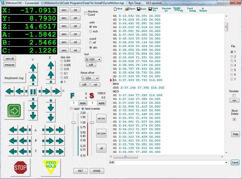
Multiple instances
One can start as many PrusaSlicer G-code Viewers as he wishes either by opening a G-code from the "File->G-code preview" menu, by starting the G-code viewer application, or by double-clicking on a G-code file in a File Explorer/Finder.
How it works
From the technical point of view, the stand-alone G-code viewer is a PrusaSlicer in disguise. The stand-alone G-code viewer is started as a new PrusaSlicer process. The way how the G-code viewer process is started is platform specific:
WindowsThe PrusaSlicer.dll contains all the code while the prusa-slicer.exe, prusa-slicer-console.exe and the new prusa-gcodeviewer.exe wrappers just load PrusaSlicer.dll with the proper parameters.
OSXThe application distribution format supports a single binary, which in our case is PrusaSlicer.app/Contents/MacOS/PrusaSlicer. For command-line usage, this binary may be symlinked to prusa-gocdeviewer to start in a G-code viewer mode.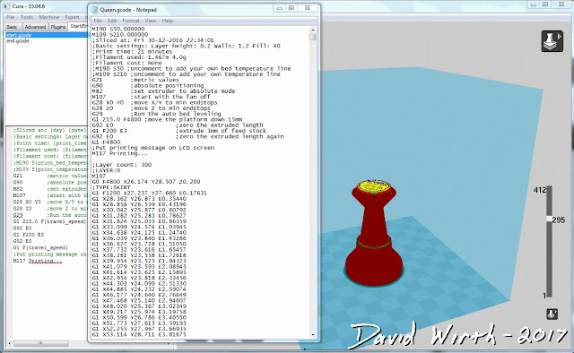 Starting new instances of PrusaSlicer does not quite fit the OSX system, as the Finder only expects a single instance of a GUI application to be running. Thus when drag & dropping onto a dock icon of PrusaSlicer resp. G-code viewer, the file is sent to the first instance of PrusaSlicer resp. G-code viewer.
We support two binary distributions: AppImage and .tar.bz2. The .tar.bz2 format contains a new prusa-gcodeviewer starter script, while the AppImage may be symlinked to prusa-gcodeviewer to start the G-code viewer. The AppImage works by mounting the zipped filesystem image embedded inside the AppImage file and starting the application from there. It is not recommended to start prusa-gcodeviewer from an already mounted AppImage, as the AppImage will be unmounted when the PrusaSlicer that mounted it closes. When the user starts a G-code viewer from an AppImage PrusaSlicer application, another AppImage is mounted by the G-code viewer, which means the PrusaSlicer binary is being loaded into RAM the second time. Therefore if one is low on RAM, it is recommended to use the .tar.bz2 distribution instead of the AppImage until the AppImage is improved to support multiple processes running from a single mounted AppImage.
what are start (initial) commands g code
The current level of development of additive technologies allows users to recreate complex technical objects without a detailed analysis of the essence of the technological process. At the same time, knowledge of G-code and the ability to use it is necessary for every owner of a 3D printer. Effective use of code allows you to dive deeper into the process and take into account all the nuances when printing products. Also, the ability to read and edit the G-code is necessary for the selection of technical parameters when printing and calibrating the device. nine0003
What is a G-code?
G-code is a programming language for machines and machine tools with an integrated numerical control module.
It was developed by the Electronic Industries Alliance in the first half of the 1960s. Programs created using this code have a rigid and extremely consistent structure. G-code lacks cycles, functions, and logical commands; its capabilities allow you to configure the equipment only in such a way that it performs only those actions that were embedded in the computer. nine0003
G-code for 3D printers can be generated by a special program - a slicer - by preloading a 3D model into it and setting the required printing parameters.
G-code is used by the vast majority of popular printers. Its popularity is due to its ease of use and the ability to generate code in any available slicers, including Cura, Chitubox, Simplify3D, Slic3er, etc. You can edit the written program in a regular notepad or NotePad ++, which is available to all users of the Windows operating system. nine0003
But there are cases when printing devices work on encrypted G-code, for example - Zortrax, which uses its own slicer, which generates a file in the Z-code extension.
Files created in this way cannot be opened using standard programs and third-party slicers.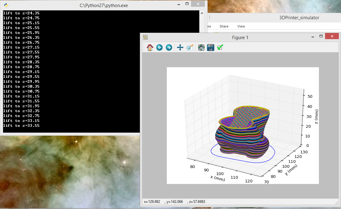
Regardless of the type of encryption, the code consists of lines, each of which is a frame. For each frame or group of frames, developers write comments that are highlighted in the code feed with a semicolon. nine0003
Basic language commands
All basic language commands begin with the letter G. They are responsible for the following actions:
- Linear and circular movement of the working device along a given trajectory at a set speed.
- Perform standard operations such as starting fans, heating elements, etc.
- Set parameters and coordinate system.
Commands whose names begin with M or T are considered additional. M commands are auxiliary, technological. They are responsible for the use of heating, cooling, reading parameters and their subsequent output to the display of the printing device. nine0003
The T commands are responsible for changing the tool used or moving from one extruder to another.
Each line (frame) of the G-code carries an encrypted specific command, as well as a set of characteristics that determines the operation of the equipment: the operating time of the drives, the amount of material supplied, its heating, etc.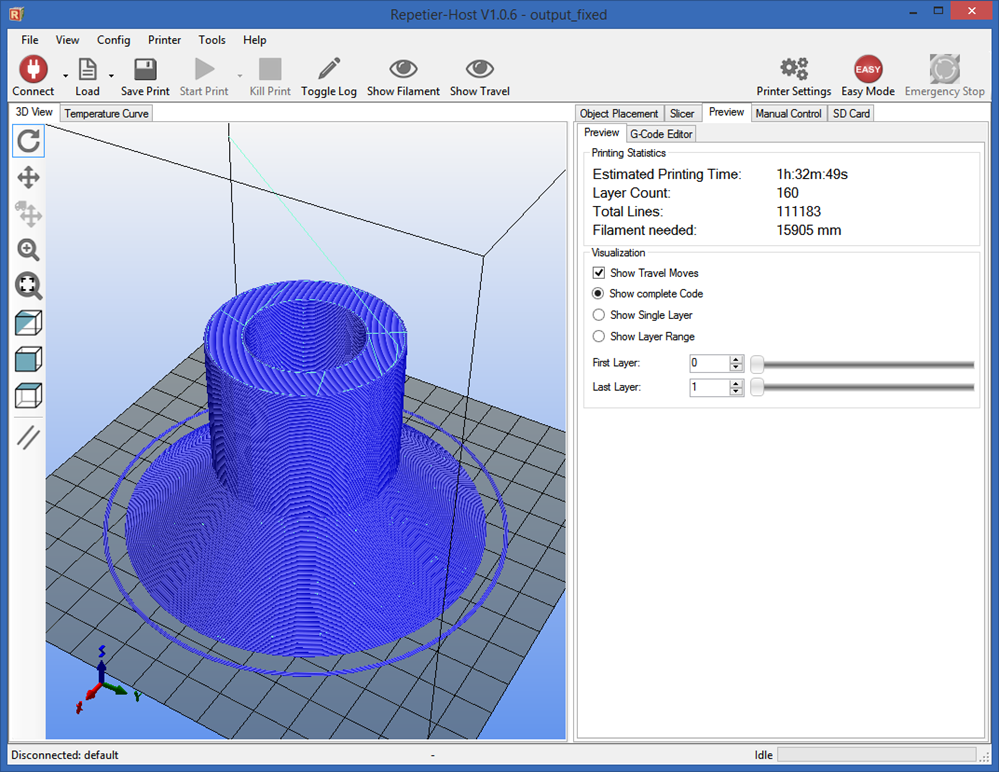
Development and popularization of special programs -slicers helped optimize and make the programming process automatic. The code obtained using modern software, as a rule, does not require correction, and if it does, then the developer has to make changes not to the entire code, but to several lines, adjusting one or more parameters. nine0003
How 3D printer software works
Each of the G-code strings is a command that the printing device must execute. The principle of operation of software for 3D printers is to split 3D models into many layers located in a horizontal plane.
Each of them, regardless of the method of creation, further goes through another breakdown into many lines of different thicknesses and widths, the parameters of which are set by the developer.
For example, the line width for a 3D printer using FDM technology must correspond to the diameter of the nozzle, and the height must correspond to the thickness of the extruded material layer.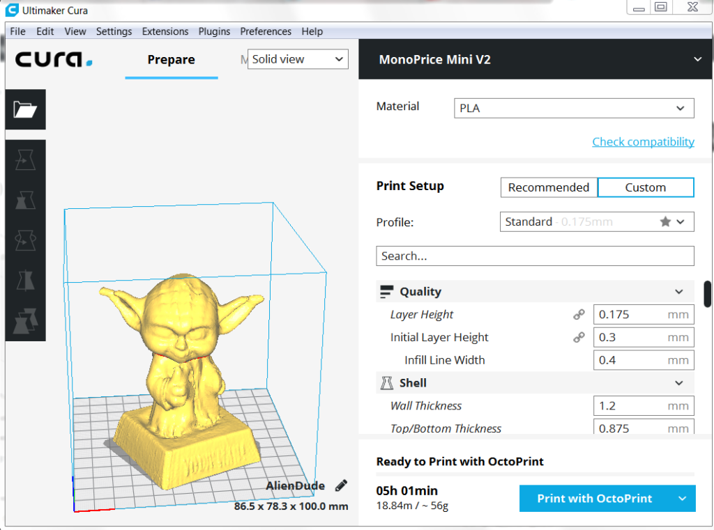
Each vector in the G-code motion path can be described in terms of the Cartesian coordinate system along which the extruder is moving. Also, this file additionally specifies related parameters: heating, extruder speed, material feed speed, etc.
When to use a G-code? nine0005
Editing a G-code compiled by slicers is useful in the following cases:
- When making spot edits to the code.
- For setting special settings, including changing the heating temperature of the extruder during printing, etc.
- For solving problems. To eliminate them, developers can add a special command, for example, turn on the blower or increase the heating temperature of the material.
G-code commands
The most popular G-codes are:
- G0 - used to determine the idle speed, does not provide for the operation of the tool.
- G1 – command defines coordinated movement along X, Y, Z, E axes.
- G4 - used in cases where it is necessary to designate a pause and set its time in seconds.
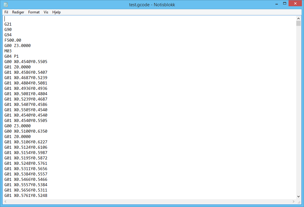
- G28 - the command is responsible for returning the extruder head to the origin of the coordinate system.
- G90 - is used when it is necessary to use absolute coordinates.
- G91 is a command used to use relative coordinates. nine0028
- G92 - determines the current target position.
Commands M
The largest group, including commands responsible for controlling the printing device.
How to edit a G-code?
A wide variety of online and offline programs can be used to edit the G-code. The most popular ones are:
- Notepad++. This is a free program available for the Windows operating system that allows you to customize G-code syntax highlighting. nine0028
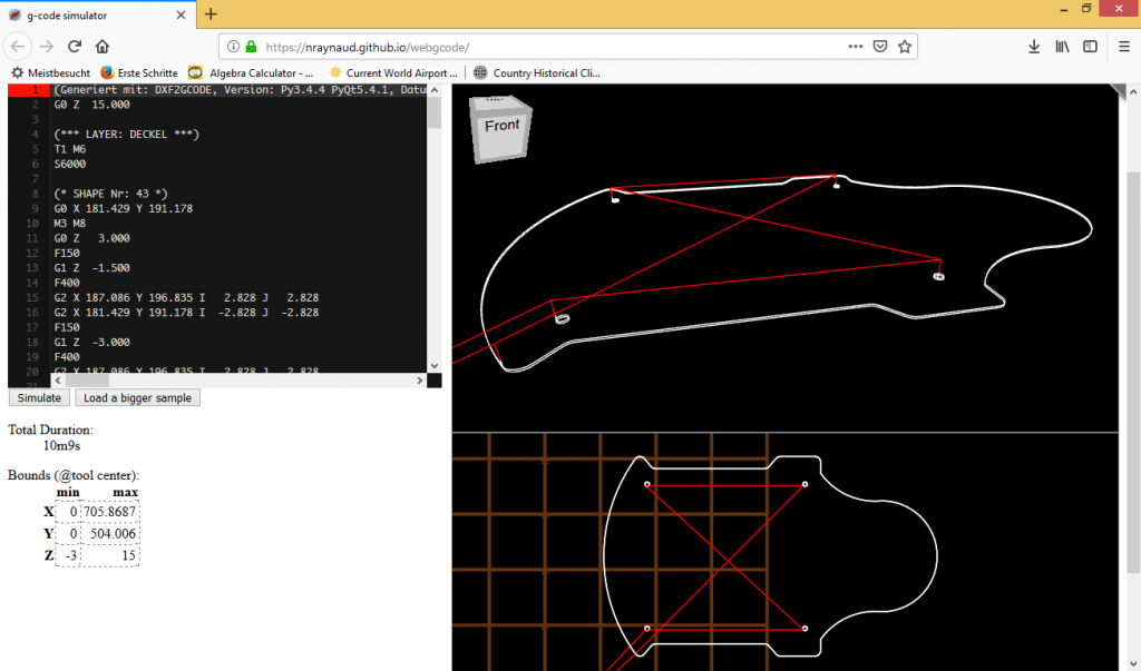
- gCodeViewer. A cloud-based application optimized for creating commands designed for 3D printers. A specific function of the program is the possibility of layer-by-layer viewing of the product in 2D mode.
- Simplify3D.
 A slicer that has its own G-code editor. When using it, the user gets access to the ability to create automatic scripts.
Knowledge of the G-code programming language is necessary for every owner of a 3D printer. By experimenting with manual slicer settings, the user can get any result based on their own experience with a variety of materials. nine0003
- March 14, 2021
- 4861
Get expert advice
3D Printing G-code Basics List and Guide
3DPrintStory 3D printing process G-code Basics for 3D Printing: List and Guide
G-code is a programming language for numerical control (CNC). In other words, it is the language that the computer that controls the car speaks, and it transmits all the commands necessary for movement and other actions.
Although G-code is a standard language for various desktop and industrial equipment, it can be very familiar with a 3D printer. You may not have figured this out yet, and that's okay, since 3D slicers generate G-code "automatically". nine0003
However, if you want to get a deeper understanding of 3D printing, it's important to learn the basics of G-code. This knowledge will allow you to better diagnose and control 3D printing processes, as well as configure 3D printer firmware such as RepRap or Marlin.
In this article, we'll cover the basics of G-code, including how to read, understand, and write commands, even if you're new to programming!
What is a G-code?
For those unfamiliar with programming in general, you can think of G-code as successive lines of instructions, each telling the 3D printer to perform a specific task.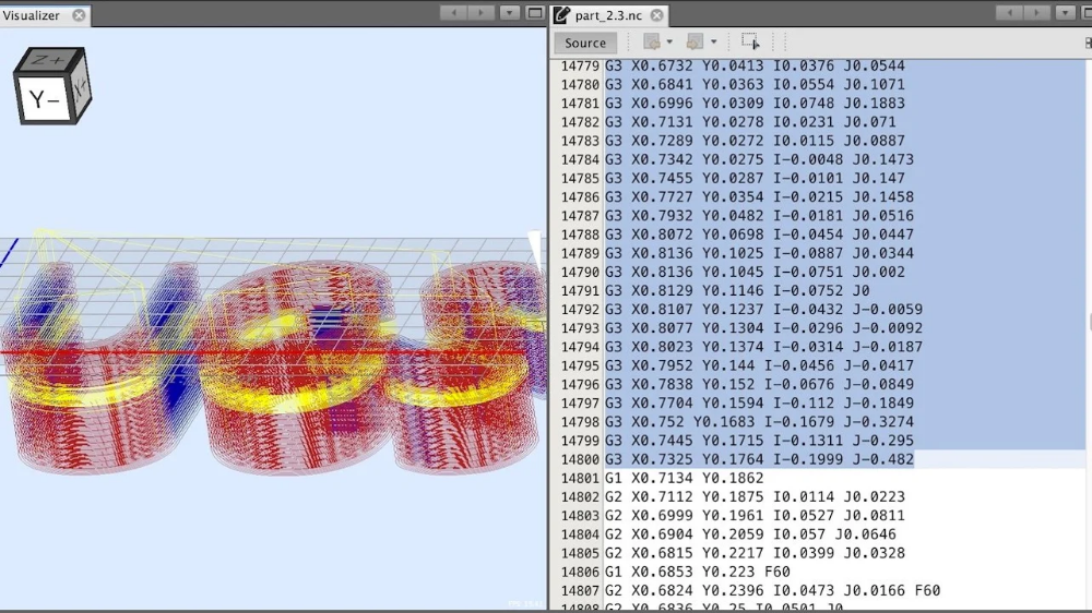 These lines are called commands, and the printer executes them one after the other until it reaches the end of the code. nine0003
Although the term "G-code" is used to refer to a programming language in general, it is also one of two types of commands used in 3D printing: "basic" and "auxiliary" commands.
The main command lines are responsible for the types of motion in the 3D printer. Such commands are denoted by the letter "G". In addition to controlling the three positive axes performed by the printhead, they are also responsible for the extrusion of the filament.
On the other hand, different commands make the machine perform non-geometric tasks. In 3D printing, such tasks include nozzle and bed heating commands, as well as fan control, and so on. Auxiliary commands are denoted by the letter "M". nine0003
G-code syntax
Each G-code command line has a specific syntax. Each line corresponds to only one command, which can lead to very long codes.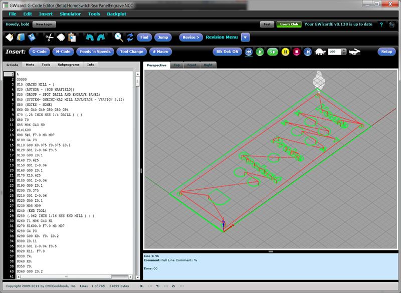
The first argument of any string is the command code itself. As you have seen, this can be a code like "G" or "M" followed by a number identifying the command. For example, "G0" corresponds to a linear movement command.
Next are the parameters that define the command more precisely. For example, for a G0 linear motion command, you can add an end position and a travel speed, also indicated in capital letters. Each command has its own set of options, which we will discuss below. nine0003
G-code comments
When you read the G-code of a command, you will see semicolons after letters and numbers that explain what the code does. Here is an example of a line with a comment to the code:
G1 X25 Y5; I comment the code!
Programmers often need to include plain language explanations so that other programmers can understand certain lines or sections of code. It can also happen that you forget why you wrote something in a certain way, making it hard for you to figure it out again.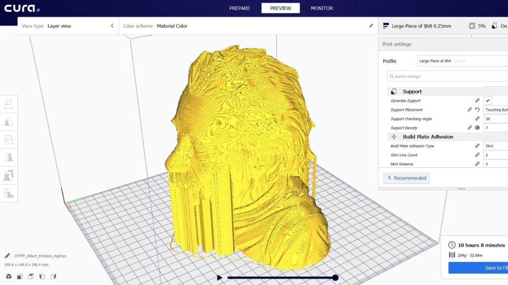 Code comments are used to solve this problem. Comments include everything (on the same line) after the semicolon and are completely ignored by the machine when executing G-code. As such, they are solely for the eyes of programmers. nine0003
Important 3D Printing Commands
Although there are literally hundreds of G-code commands, in the next few sections we'll cover the most basic and important ones. Once you get comfortable, you can learn other commands on your own.
G0 and G1: linear movement
The G0 and G1 commands execute linear movements. By convention, G0 is used for non-extrusion motions such as initial and idle motions, while G1 covers all linear motions with material extrusion. nine0003
Both commands work the same, however. The parameters for G0 or G1 include the end positions for all X, Y, and Z axes, the degree of extrusion performed during the move, and the speed determined by the feed rate in given units.
Example
G1 X90 Y50 Z0. 5 F3000 E1 tells the 3D printer to move in a straight line (G1) to end coordinates X = 90mm, Y = 50mm, Z = 0.5mm at a feedrate (F) of 3000mm / min. and extrusion (E) 1 mm of material in the extruder.
Most linear moves are within the same layer, which means that the Z coordinate is usually not specified on the command line.
G90 and G91: absolute and relative positioning
The G90 and G91 commands tell the machine how to interpret the coordinates used for movement. G90 sets "absolute positioning", which is normally the default, while G91 sets "relative positioning".
Neither command requires any parameters, and setting one automatically overrides the other. Positioning works quite simply, so let's get straight to the point. nine0003
Example
Let's say we want to move the print head X = 30 in a line. In absolute positioning mode it will look like this:
G90; sets absolute positioning G0X30; moves to X = 30
This simple move will tell the printer to move the printhead so that it is positioned at X = 30. Now, to move the relative position, we need to know where the printhead is currently located. Suppose it's X = 10:
G90; sets relative positioning G0X20; moves +20mm on the X axis
G91 first tells the 3D printer to interpret the coordinates relative to the current position (X = 10). Knowing this, it is enough just to move 20 mm in the positive direction of the X axis, thus reaching X = 30, as we would like.
G28 and G29: automatic zeroing and table calibration
Homing is the process of moving up to the physical limits for all axes of motion. The G28 command will accomplish this task by moving the printhead until the limit switches are engaged in all axes. nine0003
Moving "to zero" is important not only to orient the device, but also to prevent the printhead from running out of bounds. The G28 command is usually executed before every start of 3D printing.
A specific axis can be individually homed by including X, Y or Z as parameters. Otherwise, only G28 will provide movement to zero in all axes.
Example
G28 X Y; only X and Y axes G28; to zero on all axes
Another command, G29, starts the automatic table calibration sequence. There are many different methods for leveling a table before 3D printing. Usually this operation is provided by the firmware and not by the end users. For this reason, we will not go into details regarding the methods and parameters of commands. Just be aware that G29 is usually sent after automatic homing (G28). As a result, automatic table calibration should be performed, which is determined by the firmware. nine0003
G29; execute automatic bed leveling sequence
M104, M109, M140 and M190: temperature setting
These are important commands, which again are not motion related.
To start, the M104 command sets the target temperature that the hot end must reach and holds it until otherwise specified.
Some of the parameters include actual temperature value (S) and print head (T) for heating.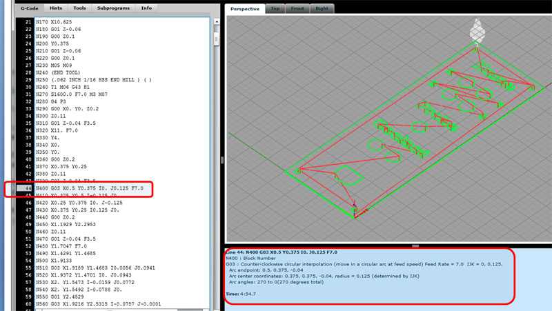 nine0003
Example
M104 S210; set the target temperature for the hot end to 210 degrees
This command line tells the 3D printer to heat the hot end to 210°C. After the target temperature is set, the printer continues the next command line by heating the hot end.
Alternatively, if we want to wait until this target is reached before moving on to the next line, we can use the M109 command.
M109 S210; set the hot end target temperature to 210 degrees and do nothing until it is reached
Setting the table temperature is very similar, but is instead set using the M140 and M190 commands:
M140 S110; set target table temperature to 110 degrees M190S110; set the target bed temperature to 110 degrees and do nothing until it is reached
M106 and M107: Fan control
Another important command for 3D printers, the M106 and M107 commands provide fan control.
M106 turns on the fan and sets its speed. This is especially useful for the part cooling fan, as during the 3D printing process, different speeds are required during the printing of the first layer and the web. nine0003
The speed parameter must be between 0 and 255. A value of 255 provides 100% power, and any number in this range will indicate the appropriate percentage.
Example
M106; turn on the fan at maximum (100%) speed M106 S128; turn on the fan and set it to 50% power
Multiple variable speed fans can be defined using the index (P) parameters since each fan is assigned an index by the firmware. nine0003
Finally, the M107 command will turn off the specified fan. If the index parameter is not specified, the partial cooling fan is usually disabled.
Program structure
Now we have a good opportunity to take a look at the actual code snippet that is used for 3D printing. As we will see later, G-code programs can be divided into three separate sections.
It is worth noting that if you use a text editor to open a G-code file created with a 3D slicer, it may not immediately start with G- or M-commands. For example, a slicer like Cura or Simplify3D runs the code, including some of the print process parameters defined earlier in the comments.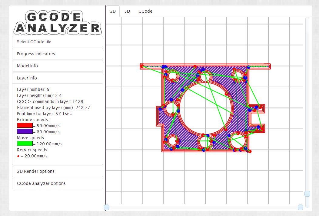 These lines do not affect the print, but instead are a quick guide to parameters such as layer height. nine0003
Stage 1: Initialization
The first section of any program includes the preparatory tasks necessary to start printing a 3D model. Below are the first six lines of G-code initialization commands from the actual 3D print job.
G90 M82 M140 S80 M104 S200 G28 G29
As we now know, the first line tells the move to use absolute positioning, and the second line tells the extruder to also interpret the extrusion in absolute units. nine0003
The third and fourth lines start heating the bed and the nozzle to the set temperatures. Note that it will not wait for the target temperature to be reached, meaning the printer will automatically reset and level the table when heated.
Some initialization routines (such as the one used by the PrusaSlicer) include a nozzle cleaning process or printing a single straight line before moving on to the 3D printing process.
Stage 2: 3D printing
This is where the magic begins. If you look at the layered G-code file, you realize that it's really impossible to understand what a nozzle actually does.
3D printing is a layer-by-layer process, so you'll find that this step involves a lot of movement in the XY plane when printing a single layer. Once this is done, one tiny movement in the Z direction will define the beginning of the next layer.
Here is an example of what G-code commands might look like in 3D printing:
G1 X103.505 Y153.291 E4.5648; movement and extrusion in the XY plane G1 X103.291 Y153.505 E4.5804; movement and extrusion in the XY plane G1 Z0.600 F3000; change layer G1 X104.025 Y154.025 F9000; movement in the XY plane G1 X95.975 Y154.025 E0.4133 F1397; moving and extruding in the XY plane
Step 3: Reloading the 3D Printer
Finally, when the 3D print is complete, some last lines of the G-code commands reset the printer to its default state. nine0003
For example, the nozzle may move to a predetermined position, the hot end and table heaters are turned off, and the motors are turned off.
M107; turn off the fan G1Z10; move the nozzle away from the print M104S0; turn off hot end heating M140S0; turn off bed heating M84; turn off the motors
Data input and output via the terminal
So far we have only talked about the fact that the computer sends G-code commands to the 3D printer (usually transmitted via an SD card). However, this is not the only way to communicate. nine0003
Some 3D printer control software, such as Pronterface and OctoPrint, allows you to interact directly with the 3D printer, in which case you can enter commands manually.
For obvious reasons, it would be impractical to print anything by sending lines of codes individually. But sometimes this method of communication is required for other purposes, such as obtaining valuable information for calibration or when the 3D printer does not have a display.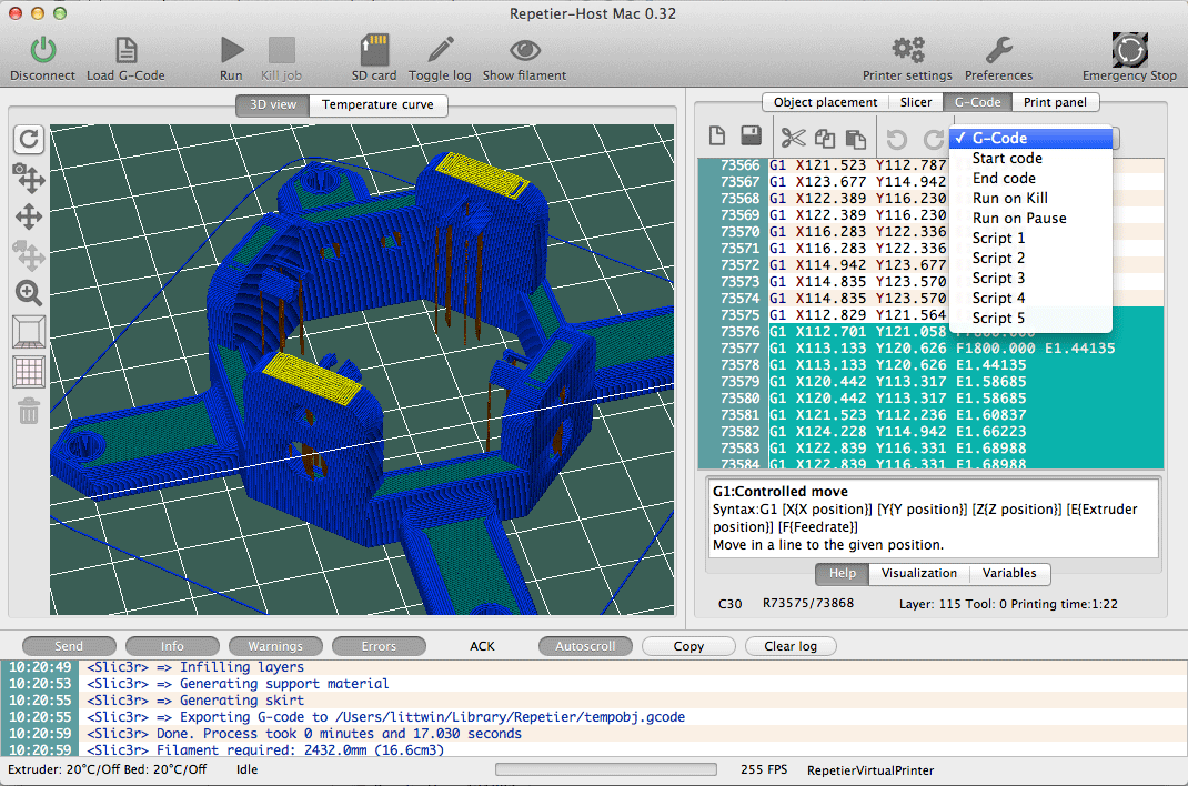
For example, the command M105 "report temperatures" will retrieve the current nozzle and bed temperatures (which can then be displayed by something like OctoPrint). nine0003
This link is also very useful for viewing and changing EEPROM settings that are hardcoded at the firmware level. Parameters such as motor steps / mm, maximum feedrate or PID controller can be visualized with M503 ("report settings"), changed manually and then saved with M500 ("save settings").
Writing G-code
By now you should be able to read and understand G-code much better. We recommend looking towards the following options to deepen your knowledge:
- online G-code visualization is a great tool to test your skills as you can write G-code commands and simulate them accordingly. It's actually a lot of fun!
- looking at exported G-code files from slicers should also give you some idea of how G-code works for 3D printing.
- You can use information from the official Marlin website as a command reference.

Learn more


