G code generator for 3d printing
YouTuber develops open-source custom G-code generator for 3D printing
0Shares
Technology YouTuber Create Inc has developed an open-source 3D printing G-code generator that allows users to create custom G-code without the need for a 3D model.
Inspired by the FullControl GCODE Designer developed by Loughborough University’s Dr. Andrew Gleadall, Create Inc’s browser-based version has been implemented as a website, making it a more accessible option. The software ultimately enables users to control every aspect of an FFF build’s toolpath, line-by-line, paving the way for previously impossible geometries such as support-free string structures and highly customizable lattices.
Create Inc explains, “A typical 3D printing pipeline has four steps. You or someone else creates a model for you to export and load it into a slicer (1). The slicer will then generate the G-code for you (2). You take this G-code and you transfer it to a printer of your choice (3), and the part is printed (4). My aim is to get rid of the first two steps, and directly generate the G-code. It’s not an approach that would work for every type of print, but it’s definitely an approach that opens up new avenues for us.”
What is G-code?
To understand the novelty of Create Inc’s G-code generator, it’s essential to understand what G-code actually is. G-code isn’t something that’s necessarily specific to 3D printing (as it’s also used in CNC machining operations), but it can be thought of as the ‘language of 3D printers’. It’s a programming language used to map out the path of a system’s toolhead over the course of a build, determining when the nozzle moves, stops, and extrudes.
The vast majority of any G-code file typically consists of two main commands: G0 and G1. The former is a very simple function that tells the printer where to move without extruding any filament, while the latter prints a straight line according to the XYZ coordinates defined in its list of parameters. Some of the other parameters associated with these commands include the travel speed, material flow rate, cooling rate, and much more.
The power of fully customizable G-code
While the combination of conventional 3D CAD software and slicing software is generally sufficient for designing most types of geometries, it still doesn’t give us full control over a printer’s movements. For example, using programs like SOLIDWORKS and Cura, it’s near impossible to 3D print pine tree-like spiny structures, a complex web-like mesh with sets of interlocking ‘strings’, or non-planar toolpaths that emulate mathematical functions like sinusoids.
For each of these parts, a custom line-by-line G-code is necessary, but commercial slicers and engineering design programs simply don’t have the functionality. Create Inc’s online G-code generator took him around two weeks to develop, and enables users to string together combinations of G0s and G1s in a programmatic manner.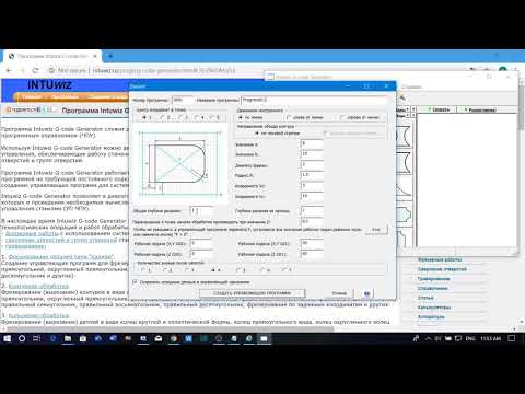 The website also has a graphical toolpath viewer that showcases all of the individual commands as they are added, enabling users to design geometries that would otherwise be tedious or downright impossible.
Create Inc’s open-source 3D printing G-code generator can be found here.
The open-source 3D printing community is a petri dish for innovation, delivering novel hardware and software previously unseen. Just this month, 3D printing content creator Teaching Tech 3D printed and showcased his own open-source version of a rare antique fractal vise. Unlike a standard straight vise, which is typically only capable of clamping straight objects, the 100 year old fractal design is capable of morphing to grip virtually any part, regardless of the complexity of the geometry.
Elsewhere, an MIT student that goes by the name of Lucas VRTech has previously designed and 3D printed a pair of low-cost finger tracking gloves for use in virtual reality. Named LucidVR, the open-source gloves grant users the ability to precisely track their fingers without the use of dedicated VR controllers.
Nominations for the 2021 3D Printing Industry Awards are now open, have your say in who is leading the industry now.
Subscribe to the 3D Printing Industry newsletter for the latest news in additive manufacturing. You can also stay connected by following us on Twitter, liking us on Facebook, and tuning into the 3D Printing Industry YouTube Channel.
Looking for a career in additive manufacturing? Visit 3D Printing Jobs for a selection of roles in the industry.
Featured image shows Create Inc. Photo via Create Inc.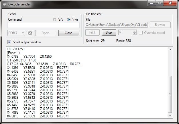
Tags Andrew Gleadall Create Inc cura FullControl GCODE Designer Loughborough University solidworks
Kubi Sertoglu
Kubi Sertoglu holds a degree in Mechanical Engineering, combining an affinity for writing with a technical background to deliver the latest news and reviews in additive manufacturing.
Open source 3D printing toolbox
What is Slic3r?
Features
Compatible with your printer too. RepRap (Prusa Mendel, MendelMax, Huxley, Tantillus...), Ultimaker, Makerbot, Lulzbot AO-100, TAZ, MakerGear M2, Rostock, Mach4, Bukobot and lots more. And even DLP printers.
Fast G-code generation is fast. Don't wait hours for slicing that detailed model. Slic3r is about 100x faster than Skeinforge. It also uses multithreading for parallel computation.
Lots of input/output formats. Slic3r reads STL, AMF and OBJ files while it can output G-code and SVG files.
Do you like the graphical interface or command line? All the features of the user-friendly interface are also available from command line. This allows to integrate Slic3r in your custom toolchain and batch operations as you like.
Open source, open development. Slic3r is open source software, licenced under the AGPLv3 license. The development is centered on GitHub and the #slic3r IRC channel on FreeNode, where the community is highly involved in testing and providing ideas and feedback.
Dependencies? Nah. Slic3r is super-easy to run: download, double click and enjoy. No dependencies needed. Hassle-free. For MacOS X, Windows, Linux.
Print with dual multiple extruders. Print beautiful colored objects, or use your secondary extruder to build support material. Or put a larger nozzle on it and print a faster infill.
Use brim for the best adhesion. This unique feature improves built plate adhesion by generating a base flange around your objects that you can easily remove after printing.
Microlayering: save time, increase accuracy. You can choose to print a thicker infill to benefit from low layer heights on perimeters and still keep your print time within a reasonable amount.
Compose a plate but print one object at time. Use the built-in plating interface that allows to place objects with drag-and-drop, rotate and scale them, arrange everything as you like. The sequential printing feature allows to print one complete object at time in a single print job.
Cool cooling strategies. A very smart cooling logic will regulate your fan speed and print speed to ensure each layer has enough time to cool down before next one is laid on it.
Manage multiple printers, filaments and build styles. The configuration handling system was designed for people working with multiple machines and filaments: you can save configurations as presets for each category avoiding to multiply your saved configurations.
Enjoy support material. Automatic generation of support material for overhangs.
Gallery
Links
The RepRap Project
G-CODE in Russian for 3D printing (Mini-guide)
Often, for high-quality printing, and especially when selecting print parameters, it is necessary to be able to read and edit the G-code during calibration.
A commonplace example: setting your own values for the "Temperature Tower" or creating start and end blocks of codes in slicers for a specific printer.
On some sites (like reprap.org/wiki/G-code) on the Russian-language pages, the commands are only partially described in Russian, and the rest in English. On some domestic sites, the commands are translated into Russian, but some are given with errors - stupidly copy-paste a clumsy translation.
Tired of searching through different sites, trying to find the CORRECT description of a particular command and its parameters.
I made myself such a mini-reference book. I'll be glad if anyone else finds it useful.
I tried to describe the maximum number of commands used, except for very specific ones.
(Yes, special commands for deltas, for example, sorry, I consider them specific and not necessary for me)
However, most commands are supported by all printers and firmware.
Attention! Compliance of commands and parameters is checked only for Marlin firmware.
G-commands
G0(G1) Xnnn Ynnn Znnn Ennn Fnnn – movement.
G0 - fast idle
G1 - linear working travel
Xnnn, Ynnn, Znnn – coordinates.
Еnnn - amount of extruded material in mm (with negative values - retract).
Fnnn – travel speed in mm/min (this speed will be used until the next change).
G0 X12 (will move 12mm in X)
G0 F1500 (Set travel speed to 1500 mm/min.)
G1 X90.6 Y13.8 E22.4 (Move 90.6mm in X and 13. 8mm in Y while extruding 22.4mm of material.)
G4 .
Pnnn - Timeout, in milliseconds
Snnn - Timeout in seconds.
"G4 S2" and "G4 P2000" - equivalent to
G10 - Plastic rollback (Retract)
Filament rollback according to M207 settings.
G11 - Plastic feed
Feed / reposition the head according to M208 settings.
G20 - Inch unit setting
G21 - Setting the units in millimeters
From now on, the reading will be in inches/millimeters.
G28 - Move to start ("home") until limit switches actuate
G28 – home on all axes.
G28 X Z - Move home only in X and Z axes
G29 - Create table curvature mesh (MESH_BED_LEVELING)
The command allows you to create a compensation (Z-height) grid and use it later when printing. The grid can be used repeatedly even after the printer is turned off.
After using the G28 command, the mesh created by the G29 command flies off.
It is necessary to save the rhinestone mesh after it has been created! To recall the grid from memory, use the M420 command.
Be sure to use G28 before using G29, otherwise the mesh will be incorrect.
Creating Mesh Bed Leveling manually (via commands):
1. Enter G29 S0 to start meshing.
2. Enter G29 S1 to set the first grid point.
3. Align the nozzle with paper (as usual).
4. Enter G29 S2 to save the value and jump to a new point
5. Repeat steps 3 and 4 until the creation procedure is completed.
6. Enter M500 to write the resulting mesh to EEPROM.
Creating Mesh Bed Leveling using the printer menu (the function must be active in the firmware):
1. Select Prepare followed by Auto home (aka G28 command).
2. Select Prepare and then Level Bed.
3. Wait for on-screen instructions to begin. Press the "twist" on the screen when the inscription "Click to Begin" appears. The head will go to the first grid point.
4. Use the thumbwheel to raise or lower the nozzle to align the nozzle with the paper. Same as when leveling the table. After you have achieved the desired gap between the nozzle and the piece of paper, press the "twist". The head will move to a new grid point.
5. Repeat step 4 until the program has passed all points.
6. When finished, enter the Control menu and select the Store memory item to save the created mesh to EEPROM.
To use the grid stored in EEPROM when printing, use the command
M420 S1 (See M420).
G90 - Setting absolute coordinates
All coordinates are absolute relative to the machine origin.
G91 - Set relative coordinates
All coordinates from now on become relative to the last position. Marlin translates all axes into relative coordinates, including the extruder.
G92 Xnnn Ynnn Znnn Ennn - Set position
This command can be used without any additional parameters.
G92 - reset all axis coordinates to zero.
Xnnn - new X coordinate
Ynnn - new Y coordinate
Znnn - new Z coordinate
Ennn - new extruder position
Example: G92 X10 E90
M-commands
M17 - Enable/Enable all stepper motors
M18 - Remove current from motors
Motors can be turned by hand. Command analog M84
M20 - List of files on SD card
M21 - SD card initialization
If the SD card is loaded when the printer is turned on, this will happen by default. The SD card must be initialized for other SD card functions to work.
M22 - Release SD card
The specified SD card will be released. On future (random) read attempts, a guaranteed error occurs. Useful before removing the SD card.
M23 - Select file on SD card
Example: M23 filename.gco
M24 - Start/continue printing from SD card
The printer will print from the file selected with the M23 command.
M25 - SD card print pause
M28 - Start writing to SD card
Example: M28 filename.gco.
A file is created on the SD card, designated as filename.gco (if the file exists, it is overwritten) and all subsequent commands to the printer are written to this file.
M29 - Stop writing to SD card
Example: M29 filename.gco
The file opened by the M28 command is closed and all subsequent commands are executed by the printer in normal mode.
M30 - Delete file from SD card
Example: M30 filename.gco. filename. gco will be removed.
M32 - Select file and start printing from SD card
Example: M32 filename.gco.
Used for SD card printing and works the same as M23 and M24
M80 - Enable ATX Power Supply
Puts the ATX power supply into sleep mode. Does not work on electronics without sleep mode.
M81 - Turn off the ATX power supply
M82 - Set the extruder to absolute mode
M83 - Set extruder to relative mode
Allows extruder to be extruder in absolute/relative units
M84 SNNN X, Y, Z, E - transfer motors to the waiting mode of
SNNN - time per seconds.
If a timeout is specified with Snnn, this command simply sets the stepper motor inactivity timeout.
If no motors (X,Y,Z or E) are specified, this command immediately disables all.
If one or more axes are specified, this command disables the specified ones immediately. For example, "M84 S10" will put stepper motors into standby mode after 10 seconds of inactivity.
M92 Xnnn Ynnn Znnn Ennn - Set the number of steps per axis per unit
Ennn - steps per unit for extruder
Examples: M92 X87.489 Y87.489 Z87.489 or M92 E420
Allows you to set the number of steps per unit (usually mm) for motors. These values are replaced with the values from the firmware at power up unless written to the EEPROM see M500.
M104 Snnn - Set extruder temperature and DO NOT wait
Snnn - Set temperature
Example: M104 S190
Sets the temperature of the active extruder 190C and immediately returns control (that is, DOES NOT WAIT for the extruder to reach the set temperature). See also M109
M105 - Get Extruder Temperature
Gets the temperature of the active extruder and hot bed in degrees Celsius. The temperature is transmitted to the connected computer. The response sent to the computer might look like this: ok T:201 B:117
M106 Snnn - Turn on the fan blowing part
SNNN - fan rotation of fan from 0 to 255 (127 - 50% speed)
m107 - turn off the fan
m108 - cancel the heating 9000 9000 temperature set by M109 and M190, continues printing.
M109 Snnn - Set extruder temperature and wait
Sets the temperature in Celsius and waits for it to be reached. See also M104
M110 Nnnn - Set current line number
Nnnn - Line number
Example: M110 N123
In this example, the number of the current line 123 is set. Thus, it is expected that the next line after this command will be 124.
M112 - Emergency Stop
m114 - receipt of current positions 9
M115 - Get a firmware version
m119 - get the status of ends
m140 - set the temperature of the table and DO NOT wait
Example: M140 S65
Sets the table temperature to 65C and immediately returns control (ie DOES NOT WAIT for the table to reach the set temperature). See also M190
M190 - Set table temperature and wait
Sets the temperature in Celsius and WAITS to reach it. see M140
M200 Dnnn Tnnn - Set the REAL diameter of the filament rod.
Dnnn – diameter in mm.
Tnnn – extruder number. (can be omitted for single extruder printers)
Example: M200 D1.65
Used to calculate the actual extruded volume.
See M404 for rating setting.
M201 Xnnn Ynnn Znnn Ennn - Setting of the maximum accelerations (in mm/s in sq.)
for axes.
Ennn - accelerations in mm/s in sq. for the extruder.
Only one/two of the parameters can be used.
Example: M201 X1000 Y1000 Z100 E2000
Use M500 to store parameters in EEPROM
M202 - Setting the maximum acceleration for simple (idle) movement.
!Not used in Marlin! V mm/s in sq. Example: M202 X1000 Y1000
M203 Xnnn Ynnn Znnn Ennn - Setting the maximum speed (in mm/s)
Xnnn, Ynnn, Znnn - max speed for axes
Ennn - max extruder speed.
Only one/two of the parameters can be used.
Example: M203 X6000 Y6000 Z300 E10000
Use M500 to store parameters in EEPROM.
M204 Pnnn Rnnn Tnnn - Acceleration setting (in mm/sec. in sq.)
Pnnn - Printing acceleration
Rnnn – Retract Acceleration
Tnnn - Accelerations during idle movements
Only one/two of the parameters can be used.
Example: M204 P800 T3000 R9000
Use M500 to store parameters in EEPROM.
M205 Xnnn, Znnn, Ennn - Setting the maximum jerk (jerk) (mm / s)
Xnnn - jerk along the X and Y axes. (Jerks are the same along these axes)
Znnn - jerk along the Z axis.
Ennn - extruder jerk.
Only one/two of the parameters can be used.
Example: M205 X30 Z5 - Set jerk X/Y = 30, Z jerk = 5.
Use M500 to store parameters in EEPROM.
М206 Xnnn, Ynnn, Znnn - Set offsets relative to limit switches (zero)
Similar to G92 command, but these offsets can be written to EEPROM see M500.
Example: M206 X10.0 Y10.0 Z-0.4
M207 Snnn Fnnn Znnn - Set retract parameters (bar retraction)
Snnn - positive retract value in mm.
Fnnn – feedrate mm/sec.
Znnn - lift (lift) of the head along the Z axis in mm during retract. (Helps avoid hitting the model)
Example: M207 S4.0 F2400 Z0.075
Used subsequently for G10 and G11 commands.
Use M500 to store parameters in EEPROM.
M208 Snnn Fnnn – Bar feed recovery parameters after retract
Snnn – positive feed value in mm.
Fnnn – feedrate mm/sec.
Use M500 to store parameters in EEPROM.
M209 Snnn – On/off automatic retraction
Snnn – value 1 – on, 0 – off
Used if the slicer does not support the G10 and G11 commands.
Each extrusion command will be classified as a retract, depending on the value (positive or negative).
M218 Tnnn Xnnn Ynnn – head offset setting
Tnnn - head number
Xnnn, Ynnn – X,Y coordinates.
Example: M218 T0 X50 Y10.5
M301 Hnnn Pnnn Innn Dnnn — Write hotend PID parameters(!)
Hnnn – extruder number. h2 - the first exruder (hotend).
Pnnn - Proportional gain (Kp)
Innn - Integral factor (Ki)
Dnnn - Derivative coefficient (Kd)
Example: M301 h2 P1 I2 D3
Use M500 to store parameters in EEPROM.
See M304 for writing table PID.
M302 Snnn - Allow extrusion at Snnn and above.
Snnn - Set temperature
Example: M302 S170 – enable extrusion (turn on the extruder motor) at a nozzle temperature of 170C and above. M302 S0 - extrude at any temperature.
M303 Ennn Snnn Cnnn - Start PID calibration process for table/hotend
Ennn - E0 hotend, E1 table.
Snnn is the calibration temperature.
Cnnn – number of calibration cycles. More cycles - more precise parameters.
Example M303 E1 C8 S110 – table PID calibration at 110C for 8 cycles.
The PID parameters will be displayed as a string on the terminal screen of a program running in connection with the printer, such as Repetier-Host.
M304 Pnnn Innn Dnnn - Write table PID parameters(!)
Pnnn - Coefficient proportional (Kp)
Innn - Integral factor (Ki)
Dnnn - Derivative coefficient (Kd)
Example: M301 h2 P1 I2 D3
M301 - without parameters will display the current parameters.
Use M500 to store parameters in EEPROM.
For writing extruder PID see M301.
М404 Wnnn - Setting the nominal filament thickness 1.75 or 3.
Wnnn - nominal (theoretical) filament thickness in mm.
Example: M404 W1.75
M404 - without parameters, will display the current nominal value as a string.
This value is used to determine the percentage difference in the automatic rate adjustment in response to the measured filament width and must match the value used for the filament width in slicer settings.
Set actual filament thickness, see M200.
М420 Snnn – Enable/disable the use of the table curvature compensation grid (MESH_BED_LEVELING)
Snnn – S1 on, S0 off.
M420 S1 – use the table curvature compensation grid loaded from EEPROM when printing.
See G29 to get the current status and create a table curvature compensation grid.
M500 - Save data to EEPROM
M501 - Reading data from EEPROM
M600 - Command for automatic filament change
3D Printing G-code Basics: List and Guide
3DPrintStory 3D printing process G-code Basics for 3D Printing: List and Guide
G-code is a programming language for numerical control (CNC). In other words, it is the language that the computer that controls the car speaks, and it transmits all the commands necessary for movement and other actions.
Although G-code is a standard language for various desktop and industrial equipment, it can be very familiar with a 3D printer. You may not have figured this out yet, and that's okay, since 3D slicers generate G-code "automatically".
However, if you want to get a deeper understanding of 3D printing, it's important to learn the basics of G-code. This knowledge will allow you to better diagnose and control 3D printing processes, as well as configure 3D printer firmware such as RepRap or Marlin.
In this article, we'll cover the basics of G-code, including how to read, understand, and write commands, even if you're new to programming!
What is a G-code?
For those unfamiliar with programming in general, you can think of G-code as successive lines of instructions, each telling the 3D printer to perform a specific task. These lines are called commands, and the printer executes them one after the other until it reaches the end of the code.
Although the term "G-code" is used to refer to a programming language in general, it is also one of two types of commands used in 3D printing: "basic" and "auxiliary" commands.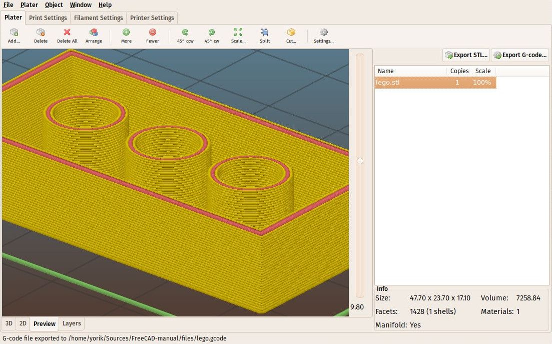
The main command lines are responsible for the types of motion in the 3D printer. Such commands are denoted by the letter "G". In addition to controlling the three positive axes performed by the printhead, they are also responsible for the extrusion of the filament.
On the other hand, different commands make the machine perform non-geometric tasks. In 3D printing, such tasks include nozzle and bed heating commands, as well as fan control, and so on. Auxiliary commands are denoted by the letter "M".
G-code syntax
Each line of G-code commands has a specific syntax. Each line corresponds to only one command, which can lead to very long codes.
The first argument of any string is the command code itself. As you have seen, this can be a code like "G" or "M" followed by a number identifying the command. For example, "G0" corresponds to a linear movement command.
Next are the parameters that define the command more precisely. For example, for a G0 linear motion command, you can add an end position and a travel speed, also indicated in capital letters. Each command has its own set of options, which we will discuss below.
G-code comments
When you read the G-code of a command, you will see semicolons after letters and numbers that explain what the code does. Here is an example of a line with a comment to the code:
G1 X25 Y5; I'm commenting out the code!
Programmers often need to include plain language explanations so that other programmers can understand certain lines or sections of code. It can also happen that you forget why you wrote something in a certain way, making it hard for you to figure it out again. Code comments are used to solve this problem. Comments include everything (on the same line) after the semicolon and are completely ignored by the machine when executing G-code. As such, they are solely for the eyes of programmers.
Important 3D Printing Commands
Although there are literally hundreds of G-code commands, in the next few sections we'll cover the most basic and important ones. Once you get comfortable, you can learn other commands on your own.
G0 and G1: linear movement
The G0 and G1 commands execute linear movements. By convention, G0 is used for non-extrusion motions such as initial and idle motions, while G1 covers all linear motions with material extrusion.
Both commands work the same, however. The parameters for G0 or G1 include the end positions for all X, Y, and Z axes, the degree of extrusion performed during the move, and the speed determined by the feed rate in given units.
Example
G1 X90 Y50 Z0.5 F3000 E1 tells the 3D printer to move in a straight line (G1) to end coordinates X = 90mm, Y = 50mm, Z = 0.5mm at a feedrate (F) of 3000mm / min. and extrusion (E) 1 mm of material in the extruder.
Most linear moves are within the same layer, which means that the Z coordinate is usually not specified on the command line.
G90 and G91: absolute and relative positioning
The G90 and G91 commands tell the machine how to interpret the coordinates used for movement. G90 sets "absolute positioning", which is normally the default, while G91 sets "relative positioning".
Neither command requires any parameters, and setting one automatically overrides the other. Positioning works quite simply, so let's get straight to the point.
Example
Let's say we want to move the print head X = 30 in a line. In absolute positioning mode it would look like this:
G90; sets absolute positioning G0X30; moves to X = 30
This simple move will tell the printer to move the printhead so that it is positioned at X = 30. Now, to move the relative position, we need to know where the printhead is currently located. Suppose it's X = 10:
G90; sets relative positioning G0X20; moves +20mm in the X direction
G91 first tells the 3D printer to interpret the coordinates relative to the current position (X = 10). Knowing this, it is enough just to move 20 mm in the positive direction of the X axis, thus reaching X = 30, as we would like.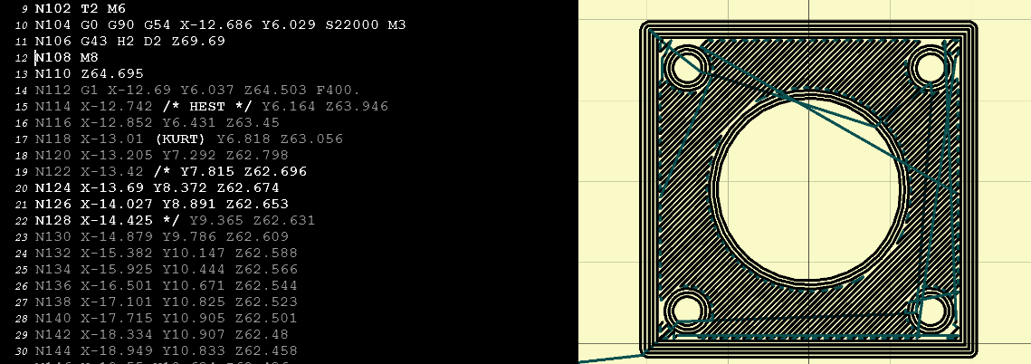
G28 and G29: automatic zeroing and table calibration
Homing is the process of moving up to physical limits for all axes of motion. The G28 command will accomplish this task by moving the print head until the limit switches on all axes are engaged.
Moving "to zero" is important not only to orient the device, but also to prevent the printhead from running out of bounds. The G28 command is usually executed before every start of 3D printing.
A specific axis can be individually homed by including X, Y or Z as parameters. Otherwise, only G28 will provide movement to zero in all axes.
Example
G28 X Y; only X and Y axes G28; to zero on all axes
Another command, G29, starts the automatic table calibration sequence. There are many different methods for leveling a table before 3D printing. Usually this operation is provided by the firmware and not by the end users. For this reason, we will not go into details regarding the methods and parameters of commands. Just be aware that G29 is usually sent after automatic homing (G28). As a result, automatic table calibration should be performed, which is determined by the firmware.
G29; execute automatic bed leveling sequence
M104, M109, M140 and M190: temperature setting
These are important commands, which again are not motion related.
To start, the M104 command sets the target temperature that the hot end must reach and holds it until otherwise specified.
Some of the parameters include actual temperature value (S) and print head (T) for heating.
Example
M104 S210; set target temperature for hot end to 210 degrees
This command line tells the 3D printer to heat the hot end to 210°C.
Alternatively, if we want to wait until this target is reached before moving on to the next line, we can use the M109 command.
M109 S210; set the hot end target temperature to 210 degrees and do nothing until it is reached
Setting the table temperature is very similar, but instead set using the M140 and M190 commands:
M140 S110; set target table temperature to 110 degrees M190S110; set the target bed temperature to 110 degrees and do nothing until it is reached
M106 and M107: Fan control
Another important command for 3D printers, the M106 and M107 commands provide fan control.
M106 turns on the fan and sets its speed. This is especially useful for the part cooling fan, as during the 3D printing process, different speeds are required during the printing of the first layer and the web.
The speed parameter must be between 0 and 255. A value of 255 provides 100% power, and any number in this range will indicate the appropriate percentage.
Example
M106; turn on the fan at maximum (100%) speed M106 S128; turn on the fan and set it to 50% power
Multiple variable speed fans can be identified using the index (P) parameters since each fan is assigned an index by the firmware.
Finally, the M107 command will turn off the specified fan. If the index parameter is not specified, the partial cooling fan is usually disabled.
Program structure
Now we have a good opportunity to look at the actual code snippet that is used for 3D printing. As we will see later, G-code programs can be divided into three distinct sections.
It is worth noting that if you use a text editor to open a G-code file created with a 3D slicer, it may not immediately start with G- or M-commands. For example, a slicer like Cura or Simplify3D runs the code, including some of the print process parameters defined earlier in the comments. These lines do not affect the print, but instead are a quick guide to parameters such as layer height.
Stage 1: Initialization
The first section of any program includes the preparatory tasks necessary to start printing a 3D model. Below are the first six lines of G-code initialization commands from the actual 3D print job.
G90 M82 M140 S80 M104 S200 G28 G29
As we now know, the first line tells the move to use absolute positioning, and the second line tells the extruder to also interpret the extrusion in absolute units.
The third and fourth lines start heating the bed and the nozzle to the set temperatures. Note that it will not wait for the target temperature to be reached, meaning the printer will automatically reset and level the table when heated.
Some initialization routines (such as the one used by the PrusaSlicer) include a nozzle cleaning process or printing a single straight line before moving on to the 3D printing process.
Stage 2: 3D printing
This is where the magic begins. If you look at the layered G-code file, you realize that it's really impossible to understand what a nozzle actually does.
3D printing is a layer-by-layer process, so you'll find that this step involves a lot of movement in the XY plane when printing a single layer. Once this is done, one tiny movement in the Z direction will define the beginning of the next layer.
Here is an example of what G-code commands might look like in 3D printing:
G1 X103.505 Y153.291 E4.5648; movement and extrusion in the XY plane G1 X103.291 Y153.505 E4.5804; movement and extrusion in the XY plane G1 Z0.600 F3000; change layer G1 X104.025 Y154.025 F9000; movement in the XY plane G1 X95.975 Y154.025 E0.4133 F1397; moving and extruding in the XY plane
Step 3: Reloading the 3D Printer
Finally, when the 3D print is complete, some last lines of the G-code commands reset the printer to its default state.
For example, the nozzle may move to a predetermined position, the hot end and table heaters are turned off, and the motors are turned off.
M107; turn off the fan G1Z10; move the nozzle away from the print M104S0; turn off hot end heating M140S0; turn off bed heating M84; turn off the motors
Data input and output via the terminal
So far we have only talked about the fact that the computer sends G-code commands to the 3D printer (usually transmitted via an SD card). However, this is not the only way to communicate.
Some 3D printer control software, such as Pronterface and OctoPrint, allows you to interact directly with the 3D printer, in which case you can enter commands manually.
For obvious reasons, it would be impractical to print anything by sending code lines individually. But sometimes this method of communication is required for other purposes, such as obtaining valuable information for calibration or when the 3D printer does not have a display.
For example, an M105 "report temperatures" command will retrieve the current nozzle and bed temperatures (which can then be displayed by something like OctoPrint).
This link is also very useful for viewing and changing EEPROM settings that are hardcoded at the firmware level. Parameters such as motor steps / mm, maximum feedrate or PID controller can be visualized with M503 ("report settings"), changed manually and then saved with M500 ("save settings").
Writing G-code
By now you should be able to read and understand G-code much better. We recommend looking towards the following options to deepen your knowledge:
- online G-code visualization is a great tool to test your skills as you can write G-code commands and simulate them accordingly. It's actually a lot of fun!
- looking at exported G-code files from slicers should also give you some idea of how G-code works for 3D printing.
- You can use the information from the official Marlin website as a command reference.
Learn more