Fpga 3d printer
3D Printers & Additive Manufacturing
- Applications
- Industrial
- 3D Printers & Additive Manufacturing
Scalable, Accelerated Sensing and Control Supporting Evolving Algorithms and Materials
Find Partners
Boards and Kits
- Overview
- Documentation
- Solutions Stack
Overview
The 3D printing space is rapidly evolving in multiple areas such as materials and process, speed and complexity, business models from makers to large scale manufacturing. Xilinx Adaptive SoCs and FPGAs offers a number of decisive advantages for the 3D printer designer and the end user:
- For designers looking to create a flexible platform that can scale across multiple price points, even different materials and processes but with the same embedded and application architecture, Xilinx is the leader in scalable Industrial IoT platforms by offering heterogeneous embedded processing, I/O flexibility, hardware-based deterministic control, and comprehensive solutions for the lowest total cost of ownership.
- For designers looking to improve both speed and quality of the process, Xilinx offers precise, deterministic control over a scalable number of axes of motion via fast parallel processing of control loops (e.g. stepper, brushless, extruder).
- For designers looking to improve deterministic communications across internal subsystems, Xilinx’s comprehensive industrial connectivity portfolio supports diverse traditional Industrial communications, such as multiple iterations of CAN, and Industrial Ethernet standards), including support for Time-Sensitive Networking (TSN), along with common hi-speed communications like USB, PCIe, and others.
- For designers looking for a single-chip solution capable of integrated human machine interfaces (HMI), machine vision inspection systems with machine learning capabilities, remote diagnostics/control, and other emerging capabilities, Xilinx has a robust selection of in-house and ecosystem solutions
- For end users that require secure communications of intellectual property sent to a printer, Xilinx offers IEC 62443 cybersecurity built on a hardware root of trust with hardware and software cryptographic accelerators.
| Design Examples | Description | Device Support |
|---|---|---|
Click to enlarge |
| Xilinx Adaptive SoCs Kria K26 SOM Versal AI Edge |
Documentation
Machine Vision Solutions Brochure
Functional Safety Solution Brief
Drives & Motor Control Solution Brief
Solutions Stack
Some Industrial and Healthcare IoT products need all elements of the Xilinx IIoT and HcIoT Solutions Stack, all need some.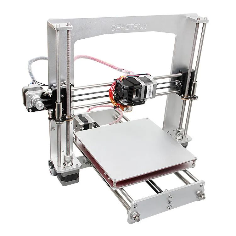 The Xilinx IIoT and HcIoT Solutions Stack is comprised of optimized Xilinx and Ecosystem building blocks and solutions used across Industrial and Healthcare IoT platforms. Starting from scratch is never something you will have to do with a Xilinx-based Industrial or Healthcare IoT system. Minimize development time and cost and maximize design reuse on your next Industrial or Healthcare IoT platform by exploring the different elements of the Xilinx IIoT and HcIoT Solutions Stack.
- Edge AI
- Embedded Software for Mixed Criticality
- Any-to-Any Connectivity
- Smarter Control
- Embedded Vision
- Functional Safety
- Cybersecurity
- Silicon Architecture
Featured Videos
SPYN Quick Take Demo
Introducing the UltraScale+ Cost-Optimized Portfolio
Industrial IoT Solution Stack
- Analytics & Machine Learning
- OS/RTOS & Hypervisors/Containers
- Any-to-Any Connectivity
- Smarter Control
- Embedded Vision
- Functional Safety
- Cybersecurity
- Silicon Architecture
3D Printing clothing design based on wireless sensors and FPGA
SHOWING 1-10 OF 14 REFERENCES
SORT BYRelevanceMost Influenced PapersRecency
Processing of Printed Dye Sensitized Solar Cells on Woven Textiles
- Jingqi Liu, Yi Li, Menglong Li, Sasikumar Arumugam, S.
 Beeby
Beeby Materials Science, Engineering
IEEE Journal of Photovoltaics
- 2019
This paper presents the novel use of screen printing and spray coating techniques to fabricate dye sensitized solar cells on textiles for wearable energy harvesting applications. Multiple functional…
Embroidered and e-textile Conductors Embedded inside 3D-printed Structures
Preliminary results show that the peak read ranges of both types of platforms are higher than 6 meters, which are suitable for versatile wireless applications.
Thin conductive structures on coated textiles
Among new areas of electronics the systems integrated with textile materials (textronics systems) grow particularly rapidly due to special properties like flexibility, low mass, and most of all, the…
Designing [with] 3D Printed Textiles
- K. Lussenburg
Materials Science
- 2014
This master thesis is the result of a graduation project for the master Integrated Product Design the faculty of Industrial Design Engineering, Delft University of Technology. The title of this…
Validation of Polymer-Based Screen-Printed Textile Electrodes for Surface EMG Detection
The results suggest that the proposed screen-printed textile electrodes may be an effective alternative to the conventional gelled electrodes for sEMG acquisition, thereby providing new opportunities in clinical and wellness fields.
Energy Harvesting Power Supplies for Electronic Textiles
Combining flexible energy harvesting techniques with a textile-based energy storage reservoir offers the potential for autonomous textile power supplies suitable for use in future integrated e-textile applications.
Flexible, Stretchable and Washable Filter Printed Directly on Textile
With the emergence of wearable and textile electronics, there is a need to study the effects of flexibility, stretchability and washing on the performance of such electronic components and systems.…
Measurement Uncertainty for Printed Textiles
- Nadile Nunes de Lima, M.
 Conni, P. Green, Markus Barbieri
 Materials Science, Computer Science
2018 Colour and Visual Computing Symposium (CVCS)
- 2018
The influence of instrument aperture and sample characteristics on the measurements was analyzed, showing that as expected larger apertures tended to give better repeatability and smaller difference in the inter-model agreement.
Piezoresistive Fabric Produced Through PVDF-Graphene Nanocomposite Film Incorporation in Textile Via Screen Printing Technique
- H. C. Bidsorkhi, F. Marra, A. D’Aloia, A. Tamburrano, G. De Bellis, M. S. Sarto
Engineering
2019 IEEE SENSORS
- 2019
A fabric sensing element has been produced by incorporating a nanocomposite film in a commercial textile via screen printing technique. The nanocomposite is a polyvinylidene fluoride (PVDF) loaded…
Study of Double Image Fusion Program on Clothing Defects Image
- Tongying Li, Hongbo Zhu
Materials Science
2018 11th International Congress on Image and Signal Processing, BioMedical Engineering and Informatics (CISP-BMEI)
- 2018
In this paper, simulating handwork of cut-paste method, a framework of split-merge combination with features of integration of multi-focus image area was built.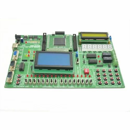 We also proposed a design of image…
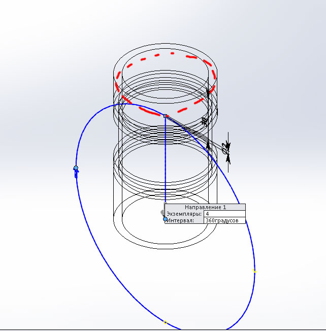
On the issue of constructing geometric primitives in the interpolator of a 3D printer with control based on FPGA
Cite:
On the issue of constructing geometric primitives in the interpolator of a 3D printer with FPGA control // Universum: technical sciences : electron. scientific magazine Musienko M.P. [and etc.]. 2014. No. 4 (5). URL: https://7universum.com/ru/tech/archive/item/1257 (date of access: 02.11.2022).
Read article:
Keywords: FPGA, interpolator, Bresenham algorithms
SUMMARY
The article deals with interpolation issues to ensure accurate movement of the FPGA-based 3D printer head. A method of interpolation for an arc based on a fast calculation of coordinates along a circle, as well as a method for reducing the number of interpolation cycles when performing calculations for a segment, is proposed.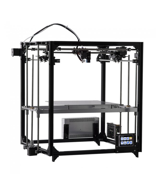 Methods for organizing the internal work of interpolation modules for a segment and an arc during calculations are proposed.
ABSTRACT
Method of interpolation for arc based on fast computation circle coordinates is proposed. In addition, method of decreasing number of interpolation iteration for cut is provided. Possibilities for organizing internal work of interpolation units in computing process are described.
References:
1. Denisov A. Application of FPGA and Bresenham algorithms to improve performance in positioning systems // Components and technologies. - No. 10. - 2013. - S. 97-100.
2. Musienko M.P., Bugaev V.I., Krainyk Ya.M., Denisov A.O. Improving the positioning speed of a 3D printer extruder using MCU / FPGA // Technical sciences - from theory to practice. - No. 12 (25). - 2013. - S. 33-36.
3. ErikZalm/ [Electronic resource]. - Access mode. — URL: https://github.com/ErikZalm/Marlin/blob/Marlin_v1/Marlin/motion_control.cpp (accessed 03/12/2014).
4. Evans B. Practical 3D Printers: The Science and Art of 3D Printing / Apress, 2012. - P. 37-40.
5. RepRap/ [Electronic resource]. - Access mode. — URL: http://reprap.org/wiki/RepRap (date of access: 03/12/2014).
The journal is registered by the Federal Service for Supervision of Communications, Information Technology and Mass Communications (Roskomnadzor), registration number EL No. FS77-54434 dated 06/17/2013
The founder of the journal is MTsNO LLC
Chief editor - Akhmetov Sairanbek Makhsutovich.
next release Submission of articles: until 15.11 Publication on the website: 25.11
Apply
New issue published 10(103) dated 10/25/2022.
Newsletter subscription
Your e-mail: *
Quick search
Journal information
Published since 2013
ISSN: 2311-5122
Languages: Russian, English.
Mass media registration certificate:
EL No. ФС77-54434 dated 06/17/2013
Download the information letter
Included in the list of the Supreme Attestation Commission of the Republic of Uzbekistan
4 Placed: 10012
Apply
3D Printers / Peripherals
Author: Konstantin Afanasiev
Computer technologies are increasingly merging with real life. However, the line between real reality and reality, so to speak, computer or virtual remains. Moving an object from one plane to another is not easy. Of course, if we are talking about text, pictures and other two-dimensional things, then printers and scanners have long made such an exchange a simple and completely ordinary thing. However, in the case of three-dimensional physical objects, everything is much more complicated.
Even technologies that allow you to see a three-dimensional computer model in real volume cannot be called very common (although they are already at the user level both in terms of price and availability). As for the possibility of touching such a model and interacting with it, then so far there is no question of home or amateur use.
And I think that most readers have not even thought about technologies that allow reproducing the model in real material. At best, they heard something out of the corner of their ear. This article will be devoted to such technologies. So to speak, for the general development.
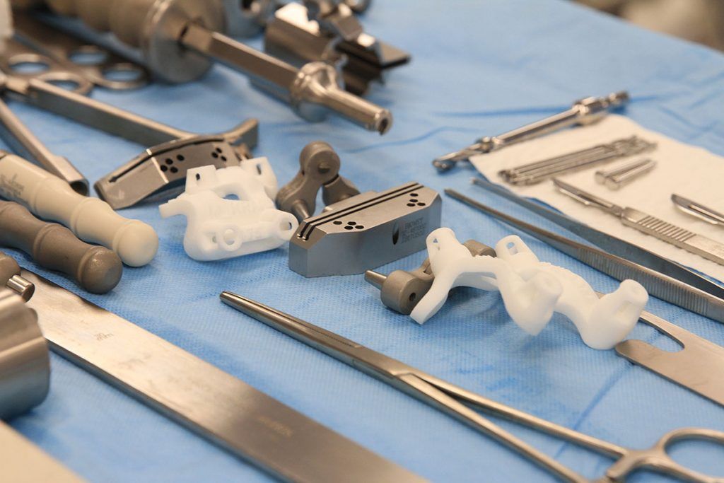
Let's start with the question, why is this needed? Why do you need to take a three-dimensional model of something and make a real object out of it? It turns out there are plenty of uses. The first, and most basic, in the industry - mainly for rapid prototyping - is to see how the model will look in the material. According to a spokesman for the aerospace company Pratt & Whitney, "the cost of developing a complex product can be greatly reduced if engineers are asked to look at a real part instead of dozens of drawings."
In addition, various tests can be carried out on the finished model even before the final product is ready. What's more, prototypes allow you to perform tests that you can't do on a finished product. For example, Porsche used a transparent plastic model of the 911 GTI transmission to study oil flow during its development. However, the main thing is that such a model can be made very quickly - and in our time of high speeds this is very important. Actually, there is a whole industry of rapid prototyping (Rapid Prototyping - RP), which is precisely engaged in the development and use of volumetric printing technologies for these purposes.
However, prototypes are not everything.![]() The next step is rapid production. Already, some RP technologies allow the manufacture of finished items from various materials. This is an ideal solution for small-scale production, since the standard manufacturing process makes it possible to do anything (within reasonable limits, of course) in a relatively short time. Again, some of the 3D printing technologies allow you to quickly produce molds - well, then the production process is already rolled out. True, prices and availability (as well as the choice of materials) still leave much to be desired.
The next step is rapid production. Already, some RP technologies allow the manufacture of finished items from various materials. This is an ideal solution for small-scale production, since the standard manufacturing process makes it possible to do anything (within reasonable limits, of course) in a relatively short time. Again, some of the 3D printing technologies allow you to quickly produce molds - well, then the production process is already rolled out. True, prices and availability (as well as the choice of materials) still leave much to be desired.
But in the future, who would refuse the opportunity to quickly make some necessary trifle at home, instead of looking for it in stores or ordering a bottle from a familiar locksmith Uncle Vasya. Actually, here you can draw a direct analogy with systems based on FPGA (that is, on programmable logic), which have made a real revolution (although it may be imperceptible for non-specialists) in electronics. FPGA technology allows you to describe electronic circuits on a computer, and then quickly implement everything described in a standard chip. The same fast prototyping, but for electronics. Moreover, if earlier all this was quite expensive and complicated, now, if desired, you can make anything - a microprocessor, DSP, microcontroller - practically at home. Volumetric printing will allow, in the future, to do the same with conventional production. However, it's time to move on from romantic dreams to the harsh truth of life and what 3D printing is now.
Micromachines
The simplest, cheapest and most affordable devices that claim to be a 3D printer actually have almost nothing to do with printers. We are talking about machine tools with program control. However, if you imagined some kind of screw-cutting monster the size of half a room (I immediately recall labor lessons or the Code of Criminal Procedure), then this is in vain. We are talking about very compact desktop machines, which are called desktop CNC machines (CNC means computer numerically controlled, or, in Russian, a machine with numerical control). These devices can be controlled directly from CAD programs and cut, cut and drill models in the material that are developed in these programs. Materials can be almost anything - from plastic or wood to soft metals (bronze, aluminum). For example, the MicroMill 2000 Desktop Machining System from MicroProto, shown in the picture (this is called a CNC milling machine), connects to a computer instead of a printer, can process a volume of 23x14x15 cm and is able to position the tool with an accuracy of hundredths of a millimeter. Machines aluminum and even mild steels. This wonderful thing costs a little less than $ 2,000.
Desktop multifunctional machine, connects instead of a printer
Part model and finished part made on a CNC machine
Another example of such devices is the MDX line of machines from Roland. The older models are designed for semi-industrial use and cost, respectively, around $20K. But the MDX-15 machine is estimated at about $ 3,000 and it can already be categorized as amateur and even home equipment. The MDX-15 also allows you to process various materials up to aluminum and bronze, has a working area of 15x10x6 cm and an accuracy of the order of hundredths of a millimeter. It connects to a computer via a serial port. By the way, Roland supplies a special piezoelectric scanning head to its machines, which allows you to do the reverse transformation - translate real objects into computer three-dimensional models.
Roland MDX 20
Machine at work
There are three main types of CNC machines: routers, mills, and lathes. What a lathe is, I think everyone understands that. And what is the difference between router and mill is easiest to understand from the figure. Of the two devices described above, the first is mill, and the second is router. By the way, machines with four degrees of freedom are also produced - to a certain extent combining the capabilities of mill and lathe. All this technique can be used both for the direct manufacture of objects according to three-dimensional models, and for the preparation of molds for casting - this significantly expands the scope. Other possible uses are engraving, fast PCB fabrication (no photomasks or etching), modeling (anyone who has built a model airframe at least once must hate jigsaw sawing for the rest of their lives), and a host of others. Well, you can get more information on desktop CNC machines at www.desktopcnc.com.
What is the difference between CNC-Mill and CNC-ROUTER
Flashcut
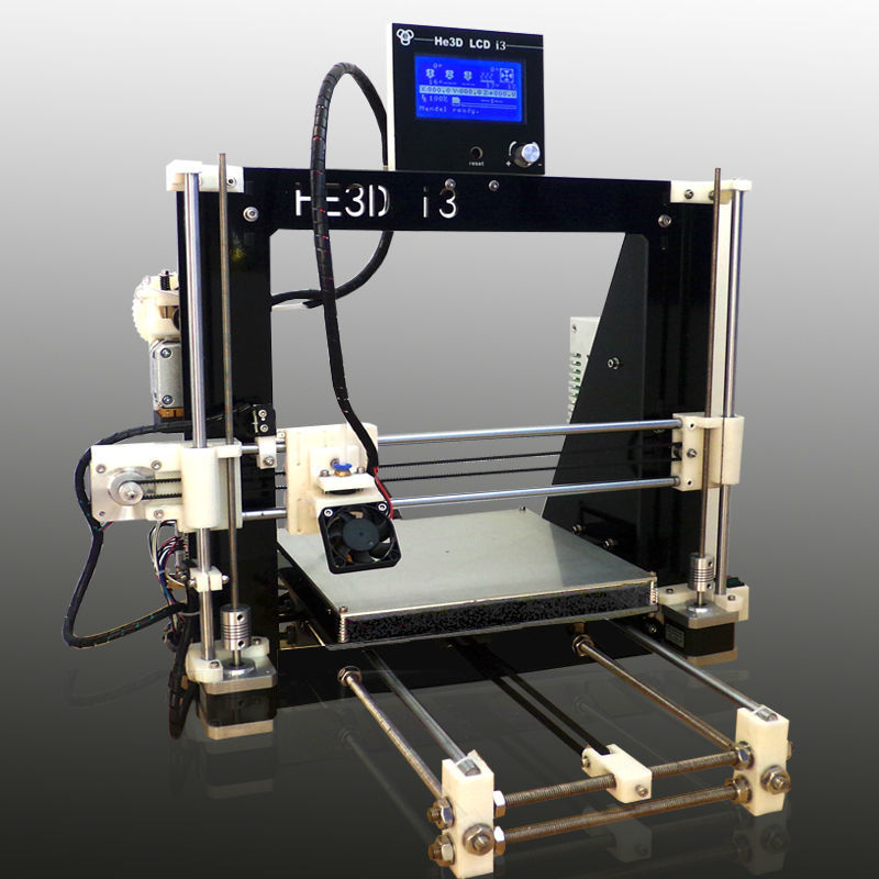
3D printer
Laser sealing
9000, and now renewal. They use several different technologies. Historically, the so-called stereolithography (StereoLithography or SLA) was developed first. The principle was invented and patented by Charles Hull back in 1986 year. Then Hull founded the company 3D Systems, which was engaged in the release of the corresponding equipment. Later, the German EOS GmbH, the Japanese Sony-DMEC and Mitsui Engineering, as well as several others, joined it. The essence of stereolithography is as follows - there is a liquid photopolymer in the working area of the printer. When illuminated with ultraviolet light, the photopolymer hardens and turns into a fairly durable plastic (photopolymers are actively used by dentists for fillings, so I think many of the readers are familiar with them). To illuminate the polymer, either an ultraviolet laser or an ordinary ultraviolet lamp is used (more on that later). The laser beam actually scans the work plane pixel by pixel and forms separate solid "pixels" until it draws a section of the model on the plastic. Then the level of the photopolymer rises (more precisely, the desktop falls along with the formed part of the model), and the next layer is drawn on top of it until the model is completely ready.
 Stereolithography makes it possible to obtain an accuracy of "imprint" of the order of tenths of a millimeter, reproduces small details well and provides a fairly even surface of the object. This technology is the best tested and the most widely used. However, it is not without its drawbacks - installations, as well as consumables, are quite expensive (the price of such a printer is about hundreds of thousands of dollars). In addition, the processed material is limited only to photopolymers.
 How the SLA machine works
This is what a stereolithography machine looks like from the inside.
CAD model and the same model, but already made in plastic using SLA technology
A faster version of this technology was originally developed by Cubital Inc. (Now apparently deceased.) It was called Solid Ground Curing or SGC for short. It also used a photopolymer as a working material, but the illumination was carried out with an ultraviolet lamp immediately for the entire working layer. Illumination was carried out through a photomask, which for each layer was printed on glass using a technology reminiscent of laser printing. Processing the entire layer simultaneously instead of pixel-by-pixel scanning with a laser beam just made it possible to achieve a fairly high speed of building an object. Now a system based on a similar principle is offered, for example, by the German company Envisiontec. The device is called Prefactory (very telling name) and is a rapid prototyping system for the end user. The machine occupies only 0.3 square meters of space, so it can be installed even in a small office. Illumination is produced using DLP (Digital Light Processing) technology, similar to those used in computer projection systems. Resolution (for one working layer) is 1280x1024 pixels at a pixel size of 150 or 90 micron. The thickness of the layers varies from 150 to 50 microns.
 The Prefactory can make prototypes around 190x152x230mm and print speeds up to 15mm per hour (height). The printer is controlled by a built-in computer running Linux, and communication with the outside world is via Ehternet via a local network. In fact, you can send jobs to the Prefactory just like you would to a regular network printer.
Envisiontec Prefactory Compact 3D Printer
Laser Sintering
An alternative 3D printing method is called laser sintering (Selective Laser Sintering - SLS). Here, as you might guess, a laser is also used, but the working material is no longer a photopolymer, but a powder of some relatively low-melting plastic. The plastic in the working volume of the SLS-machine is heated almost to the melting point, and so that it does not catch fire and does not begin to oxidize, nitrogen is supplied to the working zone. Then a powerful laser again draws a section of the part on the plastic powder, the plastic is heated above the melting point and sintered. The next layer is poured on top and the procedure is repeated. At the end of the work, the excess powder is simply shaken off the finished model. This process was developed in the late 80s at the University of Texas at Austin and patented in 1989 by university graduate Carl Deckard. The process was then commercialized by DTM Corp. Laser sintering also provides a fairly high quality parts, although their surface is porous. But the models obtained by the SLS method are the most durable and this technology, in principle, can be used for small-scale production. True, the SLS plant is quite complex and expensive, and the production rate is only a few centimeters (height) per hour (plus several hours to heat up and cool down the plant).
This is how the laser sintering machine works
This is how the SLS machine and parts made in it look like
In addition to good manufacturing accuracy and high strength of the "printouts" obtained, SLS has several other important advantages. First, laser sintering makes it possible to produce models with moving parts - for example, working hinges, push buttons, and so on. Secondly, special materials have been developed for the SLS process, allowing the direct production of metal parts. As a powder, steel microparticles are used here, coated on top with a layer of binding plastic. The sintering of the plastic takes place as usual, and then the "printed" part is fired in an oven. In this case, the plastic burns out, and the freed pores are filled with bronze. The result is an object consisting of 60% steel and the remaining 40% bronze. In terms of its mechanical characteristics, it surpasses aluminum and approaches classic stainless steel. In fact, SLS already now allows the production of full-fledged metal objects, and of arbitrary shape. In addition, there is a similar material with a ceramic or glass core - it can be used to make models that are resistant to high temperatures and aggressive chemicals. If only the process itself wasn't so expensive.
 ..
..
Laser sintering model and implementation
Lamination
Another laser 3D printing technology is lamination. It was developed by Helysis and sold under the brand name LOM (Laminated Object Manufacturing). Helysis itself ceased to exist in 2000, and several other manufacturers are now developing their equipment based on its technology. The essence of the technology is as follows - thin sheets of working material are loaded into the machine in turn, from which layers of the future model are then cut out by a laser. After cutting, the layers are glued together. Initially, special paper with a layer of adhesive was used as the material. However, thin plastics, ceramics and even metal foils can also be cut in this way.
The principle of operation of the three-dimensional printer on lamination
Inkjet printing
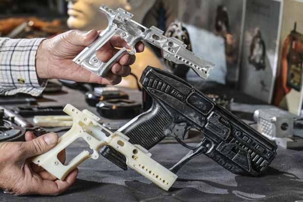
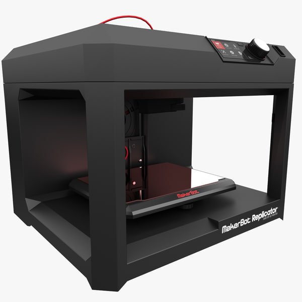
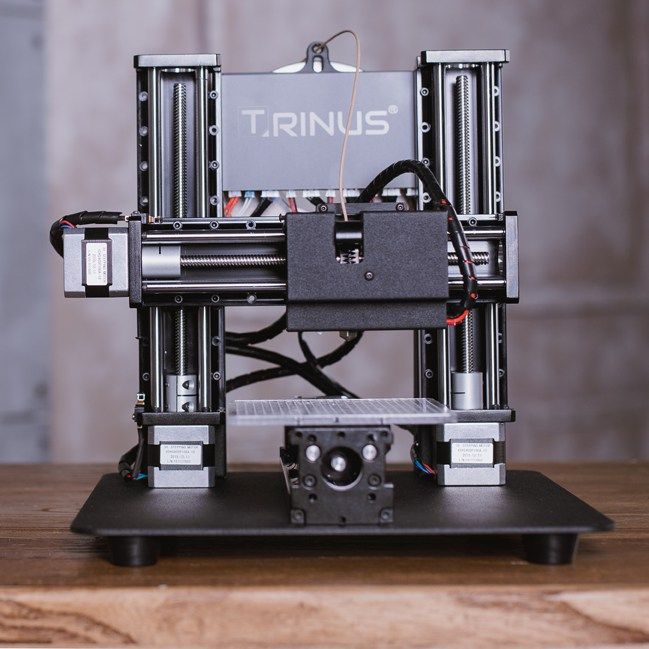
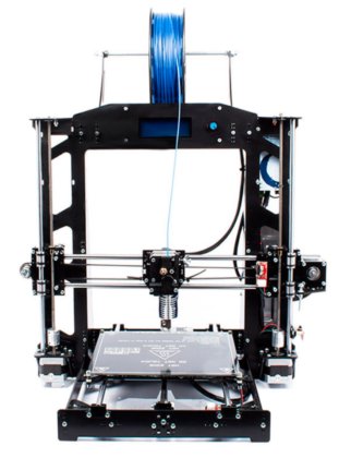
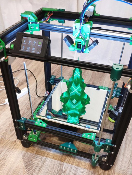
Above, so to speak, three-dimensional laser printing systems have been described. However, inkjet printers are not far behind laser printers in this area. The simplest of the "inkjet" 3D printing processes is the so-called Fused Deposition Modeling (FDM). The idea of FDM is very simple - the dispensing head squeezes drops of heated thermoplastic onto the cooled base platform (almost any industrial thermoplastic can be used as a material). Drops quickly harden and stick together, forming layers of the future object (printing here is also carried out in layers). The FDM process makes it possible to produce quite large ready-to-use parts (up to 600 x 600 x 500 mm) with sufficiently high accuracy (minimum layer thickness 0.12 mm). The fundamentals of this technology were developed 19 more88 by Scott Crump. The main manufacturer of FDM equipment is Stratasys.
How the FDM machine works
By the way, NASA is considering FDM technology as a "space factory" candidate. After all, you cannot take an unlimited number of spare parts for all equipment on a space expedition. And it is unlikely that it will be possible to place a full-fledged mechanical workshop on a spaceship. But loading a couple of hundred kilograms of the original plastic and a compact machine that can make any part out of this plastic is easy.
FDM printer at work
Another technology clearly derived from inkjet printing is the Polyjet developed by Objet Geometries. Here the inkjet head is used to print photopolymer plastic. The model, as usual, is printed layer by layer, and the resolution in the layer is 600 x 300 dpi, and the layer thickness can be reduced to as little as 16 microns. Each printed layer is polymerized into a hard plastic under the action of an ultraviolet lamp. In principle, all this is quite similar to SLA, but much faster, more accurate, simpler and more compact. At the same time, the price for Objet printers is at the level of $60K - several times less than for SLA installations. A similar system called InVison is also produced by 3D Systems, so the founding father of stereolithography also does not stand still. The price tag for this machine is about $40K - rapid prototyping systems have clearly become cheaper in recent years.
Objet Eden Rapid Prototyping System 260
And a skull model printed on it
And another "inkjet" technology, but using powder materials. It was developed at the famous Massachusetts Institute of Technology, and the Z Corporation became the first and main manufacturer of equipment. Its 3D printers are relatively inexpensive (from $10K to $30K) and are significantly faster than the devices described above. The essence of the technology is as follows - a special inkjet head (by the way, adapted from Hewlett-Packard inkjet printers) sprays an adhesive onto the powder material. Ordinary gypsum or starch is used as a powder. In "splashed" places, the powder sticks together and forms a model. Printing, as in previous cases, goes in layers, and the excess powder is shaken off at the end.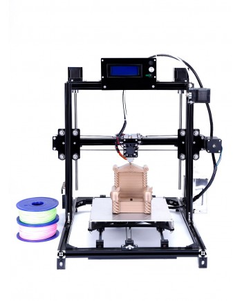 However, there is a significant difference - this printer can use an adhesive liquid with the addition of pigment dyes - which means it can print color models. The color printer from Z Corporation has 4 inkjet heads with ink-glue of primary colors, so that the resulting model can reproduce not only the shape, but also the color (that is, the texture) of its virtual prototype. True, plaster models are not very strong, but they can immediately be used as molds for casting. As for the detailing of the "imprint", it is enough to look at the given photographs to appreciate it.
It remains only to shake off the excess powder from the finished print of the model.
Head and spare parts for it, 3D color printing
Z Corporation serial 3D printer
By the way, ProMetal is developing an interesting version of the above powder inkjet printing.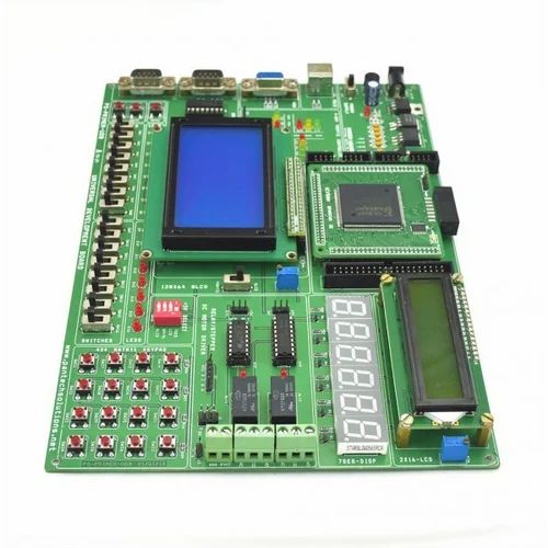 Its proprietary manufacturing process called the Direct Metal Process works exactly the same way. Only instead of gypsum powder, metal powder is used. Next, the molded product is fired in a furnace, so that the powder either melts itself or binds with a more fusible metal (as in laser sintering of metal powders). Here is another method of direct production using 3D printing.
Part made of metal using ProMetal technology
In general, the prospects for 3D printing are very bright - this technology already saves a lot of time and effort for designers and engineers. And what will happen when it becomes available at the household level. Or, at least, in the form of an inexpensive service. Imagine that you can make any object that you can think of and draw on a computer ... All you have to do is draw a model, determine the material and send an order over the Internet. This is called Distance Manufacturing on Demand. In general, such a technology is simply bound to become mass-produced sooner or later - and then everyone will have their own personal mechanical factory on the table, replacing ordinary production in small things.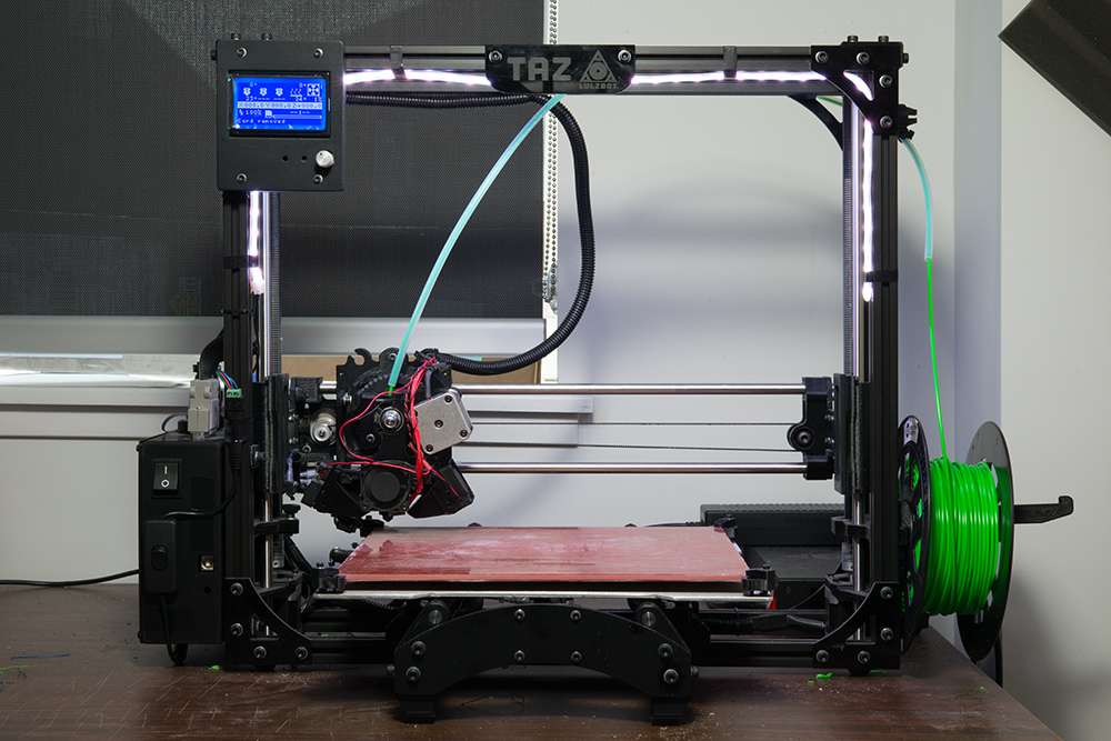 In the same way that printers have replaced printing houses and typewriting bureaus.
Meanwhile, further developments in this area are in full swing, so you can always expect something new and unexpected. For example, a group of scientists from the University of California at Berkeley is developing a 3D printing technology that would allow both form and content to be created simultaneously. The content here means neither more nor less - electronic stuffing. Let's say the printer prints the plastic case of a mobile phone and prints all the electronics inside at the same time. In principle, there are already ways to print plastic semiconductor devices and the wires connecting them. It remains only to combine them with existing 3D printer technologies and a revolutionary breakthrough in modern production is ready. No, of course, this is not an easy task, but it is quite possible to solve it.
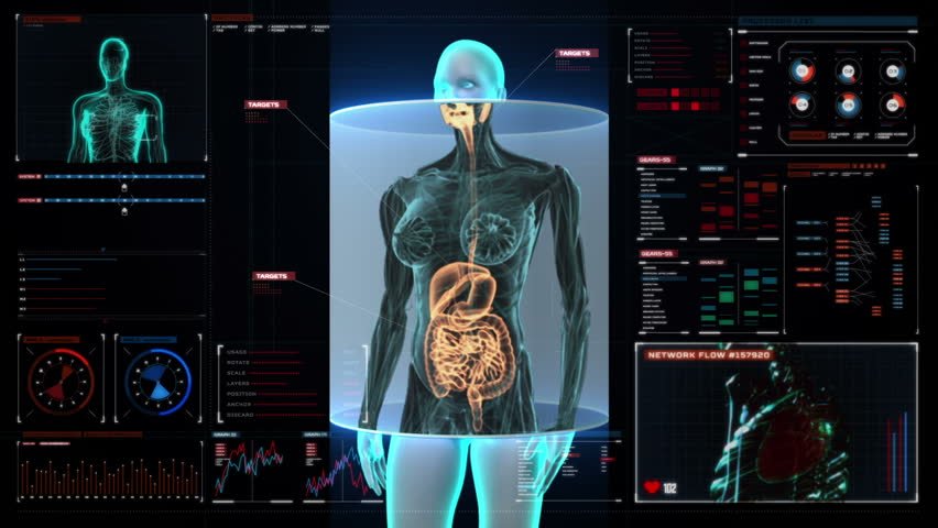
Or, for example, the developments of the University of Missouri, which allow using an inkjet printer to print original blanks of biological organs.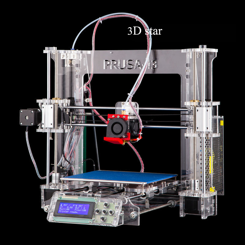 In this case, clumps of cells of a given type are used as ink. Instead of "paper" there is a special bio-gel that fixes the position of cell clumps in space. The printing is done in several layers, so that the result is a three-dimensional construction of cells, which, in principle, can imitate any organ (after the cells grow, the gel dissolves, so that hollow structures can be obtained). Of course, printing a full-fledged organ for transplantation seems too difficult for now, but work is underway.
Cellular ink printing system
For those who are interested in this topic, I can give some useful links. First, at this address is a collection of links to equipment manufacturers, technology developers and researchers. Moreover, the links are broken down by materials and production methods, so that a fairly clear picture of the state of affairs in this area immediately emerges. Secondly, at www.rpm-novation.com there is quite a good site dedicated to rapid prototyping technologies in Russian.