Solidworks threads for 3d printing
Threads In 3D printed parts
Printing the threads in 3D printed parts is possible, and as you can see from the testing video below it works quite well even in high load end use applications. Through testing we have done here at F3DP we have found its possible to print threads as small as 6-32 or M3 into 3D printed parts. This page will teach you how to go about designing in these threads for 3D printed parts.
Thread Strength Testing: Nylon 12 Material
Tensile strength test of MJF parts with larger printed in threads
Tensile strength test of MJF parts with smaller printed in threads
Thread Strength Testing: TPU Rubber Material
Tensile strength test of TPU Rubber MJF parts, helicoil thread insert vs. printed in thread
What machines is it possible to print threads into 3D printed parts with?Threads in 3D printed parts using an HP MJF machine with Nylon 12
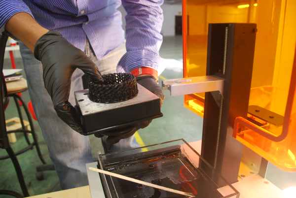
This guide will be specifically talking about threads for 3D printed parts coming off of the HP MJF technology. The MJF machine is unique in that it allows for very fine features to be printed in any orientation without the need for support while still being able to use high strength materials like Nylon. The next closest technology that would be able to produce threads would be SLS, but these machines can’t capture the same level of detail as the MJF so they are limited to 1/4-20 or M6 threads or bigger. Then there are the liquid polymer machines like Polyjet, SLA, CLIP, DLP, ect. These machines can absolutely print threads down to 8-32 or M4, but the hole must be oriented in the vertical direction from the print bed.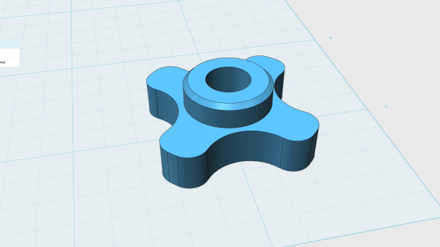 If the hole is horizontal it will end up with support in it and the 3D printed thread will not turn out. Lastly, FDM technology is not suited to print in any threads under 1/2-13 or M12, and they have to be oriented vertically from the machines print bead.
Our in-house engineering group works with all the major CAD software’s, but the one that is the easiest to use for adding threads into a 3D printed part is Solidworks. The reason for this is that it has a built in tool that will automatically add in the correct thread profile for you. For this reason this guide is built around this software, and the following video is a tutorial that will walk you through how to add threads in 3D printed parts:
How To Design 3D Printable Threads – NUTHow To Design 3D Printable Threads – BOLTHere is a really good tap / drill chart for reference.
For those not using Solidworks for their CAD design software we have also collected thread design how to video’s for a lot of the other major CAD design software’s on the market:
Our other divisions:
close ×
Get a Quote:
Upload your files and fill out the information below to begin the quoting process.
Designing and 3D Printing Threaded Parts
TriMech Blog, SOLIDWORKS
By Laura Weismantel on
In this blog, we walk through the process of working with existing geometry and adding the ever-important part of threads to it. By this I mean physical threads, not virtual threads or visualizations of idealized threads. We are talking about the real deal, physical threads modeled in your SOLIDWORKS part. Read on to find out how it’s done.
Creating the Threads
It begins with a STEP file. STEP files are extremely useful for sharing parts with anyone outside your organization because it contains the solid geometry of your model, but not the entire feature history of it. That can also present a challenge because there’s no easy way to see how the model was created. Are the threads a standard type or are they just arbitrary? If this part were to be machined that would be a problem. Luckily this is going to be a 3D printed part and I proceed with making the cap.
I started by creating a rough outline for the profile of the cap, leaving some clearance at the bottom. The only trick now is to make sure that you uncheck the option for “Merge Results.” By doing this, we are able to create two separate bodies which is the desired effect since an unremovable lid isn’t really a lid. The solid body is what Icall the lid blank.
Next, it’s time to create the threads. This is easy with some basic surface modeling techniques using offset surface, fill surface and then cut with surface. These steps are going to remove the inside of the cap so it can be screwed on to the bottle. The offset surface tool is used to quickly create a copy of the existing threads at an offset of 0.3 mm, which is a good amount of clearance for this job. This value adjusts how tight or lose the thread fits. Finally, the fill surface command is used to fill in the on side of the cap, so we can use this shape to remove exactly what we want from the solid or blank of the lid.
Printing the Threads
With that, the lid has been created. You could stop here and print what you have – it will be a functional lid for the bottle. However, if you want to take it a step further you can take the design a step further and add some cut outs and ergonomic features to really take your design to the next level. One area for improvement could be the grip of the cap. Adding some indents is quick and easy. It takes just one arc on the bottom flat face of the lid to create indents all around the cap. I used the 3-point arc tool because it is easy to snap to the existing geometry but you can create any other shape you’d like. This outline will then be patterned around the lid with the “circular sketch pattern.” SOLIDWORKS will take that initial “seed” shape and pattern it around the lid, just find a number of instances that works for you. Then simply take this sketch and extrude a cut feature through the depth of the lid to add some ergonomic grip to your lid.
Now you have a part file with two bodies – one for the lid and one for the bottle. This is known as a multi-body part. As you can see it is very easy to apply this technique to create new parts referencing existing parts. To take the lid and turn it into its own SOLIDWORKS part file use the “Insert Into New Part” option.
Now that the geometry has been created, it’s time to make the virtual part a reality by printing it using a 3D printer. In this example, I will be using a Fortus 250mc. It’s a great option to print parts you can use to test for form, fit, and function. You’ll want to always think about the best orientation of your print. This makes it cheaper by using the least amount of materials, but it also can have time and structural implications too. But not just orientation. Make sure you’re printing with the best settings for the job. Think about things like the print resolution, slice height and print density.
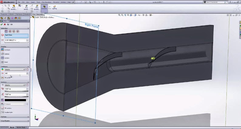
As with everything in SOLIDWORKS there is more than one way to get the job done. In the spirit of that, I wanted to share another way to create threaded geometry for us to ultimately 3D print. This time it’s not a bottle and cap but rather a mold which will create injected molded plastic parts. In this example, I begin by going directly to one of the best online resources, McMasterCarr to find the right screw size component. If you’ve never used McMasterCarr, I highly recommend you take a look at since it’s the biggest online database of parts, many of which have downloadable 3D model files. Whenever you can find an existing model, you’re going to save a ton of time.
From here we choose the right piece of hardware and then even drill down to make sure it’s the right size. To add it to the assembly we will use the “Insert Part” feature. This will bring the component into the current part file as a separate solid body. And now it’s a piece of cake to complete the assembly. With the move copy bodies command you can locate the component quickly and easily. And those are two ways you can work with threads in SOLIDWORKS.
Looking to learn more about SOLIDWORKS Sweeps and Threads?
Download our free infographic!
Metal 3D Printing - The Essential Guide
There is no hotter trend in 3D printing today than metal. We will talk about metal printing at home, how it is done on an industrial scale, about technologies, applications, printers, processes, prices and materials.
Metal 3D printing has grown in popularity over the past few years. And this is quite natural: each material offers a unique combination of practical and aesthetic qualities, can be suitable for a wide range of products, prototypes, miniatures, decorations, functional details and even kitchen utensils.
The reason metal 3D printing has become so popular is because the printed objects can be mass-produced. In fact, some of the printed parts are just as good (if not better) than those made with traditional methods.
In traditional production, working with plastic and metal can be quite wasteful - there is a lot of waste, a lot of excess material is used. When an aircraft manufacturer makes metal parts, up to 90% of the material is simply cut off. 3D printed metal parts require less energy and waste is reduced to a minimum. It is also important that the final 3D printed product is up to 60% lighter than a traditional part. Billions of dollars could be saved in the aviation industry alone—mainly through weight savings and fuel savings.
So, what do we need to know about metal 3D printing?
Metal 3D printing at home
If you want to make objects at home that will look like metal, your best bet is to look at metalized PLA filaments (Photo: colorFabb)
Where to start if you want to print metal objects at home ? Given the extreme heat required for true metal 3D printing, a conventional FDM 3D printer will not be able to do this.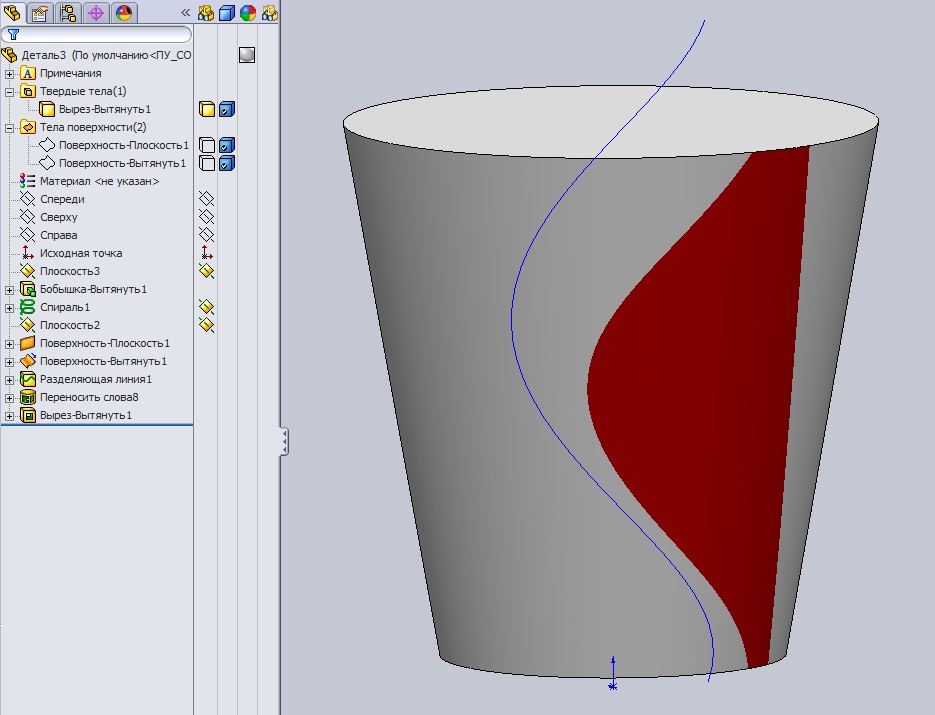
It is unlikely that in this decade it will be possible to print with liquid metal at home. Until 2020, you probably will not have a printer specialized for this purpose at home. But in a few years, as nanotechnology advances, we may see significant developments in new applications. This can be 3D printed with conductive silver, which will emit in much the same way as it does in 2D home printers. It will even be possible to mix different materials like plastic and metal in one object.
Materials for metal 3D printing at home
Even though you can't print actual metal objects at home, you can turn to plastic filament that has metal powders added to it. ColorFabb, ProtoPasta and TreeD Filaments all offer interesting metal-PLA composite filaments. These filaments, containing a significant percentage of metal powders, remain pliable enough to be printed at low temperatures (200 to 300 Celsius) on virtually any 3D printer. At the same time, they contain enough metal to make the final object look, feel, and even weigh like metal. Iron-based filaments even rust under certain conditions.
But you can go further. Typically, up to 50 percent metal powder is added to 3D printing filament. Dutch company Formfutura says they have achieved 85 percent metal powder with 15 percent PLA. These filaments are called MetalFil Ancient Bronze and Metalfil Classic Copper. They can be printed even at "moderate" temperatures from 190 to 200 degrees Celsius.
Metallic 3D Printing Filament Spools, in this case from SteelFill and CopperFill colorFabb (Steel and Bronze), Ancient Bronze (Ancient Bronze) from Formfutura
Here are the key points about metal printing at home
- Gets a unique metal surface and look
- Ideal for jewelry, figurines, housewares, replicas
- Durability
- Objects are not flexible (structure dependent)
- Objects do not dissolve
- Not considered food safe
- Typical print temperature: 195 - 220°C
- Extremely low shrinkage on cooling
- No table heating required
- Printing complexity is high, requires fine tuning of nozzle temperature, feed rate, post-processing
Preparing Your Home Printer for Metal 3D Printing
Since getting metal 3D prints is more difficult than usual, you may need to upgrade your 3D printer nozzle, especially if you are an entry-level printer. The metal filament wears it out quickly. There are hard-wearing hot-ends (like the E3D V6) that are themselves made of metal. They can withstand high temperatures and fit most printers. Be prepared for the fact that the nozzles will have to be changed frequently, because the metal filament is very abrasive.
You will also need to take care of the final finishing of the surface (cleaning, grinding, oiling, waxing or priming) so that the printed metal object shines as it should.
How much does metal filament for 3D printing cost?
And what about metal filament for 3D printing? - you ask. Here are a few examples:
- ColorFabb's 750 gram Bronzefill spool is $56.36
- ColorFabb 750g Copperfill Coil $56.36
- Protopasta's Polishable Stainless Steel PLA Composite is $56 for 56 grams of
- Protopasta's Rustable Magnetic Iron PLA Composite is $34.99 for 500 grams of
Industrial metal 3D printing
But what if you want a better result or even full metal 3D printing? Should a real "metal" 3D printer be purchased for business needs? We wouldn't recommend it - unless you're going to be doing it every day.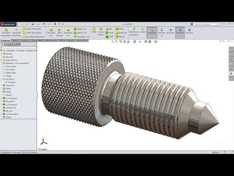 A professional metal 3D printer is expensive: EOS or Stratasys devices will cost you 100-500 thousand dollars. In addition, the costs will be even greater, since you will have to hire an operator, a worker to maintain the machine, as well as to finalize the printouts (polishing, for example). Just a note: In 2016, an affordable metal 3D printer didn't exist.
Lowering Metal 3D Printing Costs
If you are not going to start a metal 3D printing business, but still need a professionally 3D printed metal part, it is best to contact the appropriate company that provides such services. 3D printing services like Shapeways, Sculpteo and iMaterialise offer direct metal printing.
They currently work with the following metal materials in 3D printing:
- aluminum
- steel
- brass
- copper
- bronze
- sterling silver
- gold
- platinum
- titanium
If you are a jeweler, you can also order wax models for casting in precious metals.
If we talk about wax models, then in most cases they (with subsequent melting) are used when printing with metals (including gold and silver). Not all orders are carried out directly by these firms. They usually turn to other metal 3D printing companies to complete the order. However, the number of such services around the world is growing rapidly. In addition, metal 3D printing techniques are becoming more and more common in companies that offer such services.
The reason big companies love 3D printing so much is that it can be used to build fully automated lines that produce "topologically optimized" parts. This means that it is possible to fine-tune the raw materials and make the components thicker only if they must withstand heavy loads. In general, the mass of parts is significantly reduced, while their structural integrity is preserved. And this is not the only advantage of this technology. In some cases, the product turns out to be significantly cheaper and affordable for almost everyone..thumb.png.eb7e1fd20ffe7c49280960af9d52988f.png)
Please note that metal 3D printing requires special CAD programs for modeling. It is worth paying attention to the recommendations of Shapeways - 3D printing metal guidelines. To delve further into the topic, check out Statasys’ information on related 3D printers and the nuances of metal 3D printing.
Here are some examples of Benchy test model prices for metal 3D printing:
- Metal plastic: $22.44 (former alumide, PLA with aluminium)
- Stainless steel: $83.75 (plated, polished)
- Bronze: $299.91 (solid, polished)
- Silver: $713.47 (solid, mirror polished)
- Gold: $87.75 (gold plated, polished)
- Gold: $12,540 (solid, 18K gold)
- Platinum: $27,314 (solid, polished)
As you might expect, solid metal 3D printing prices are quite high.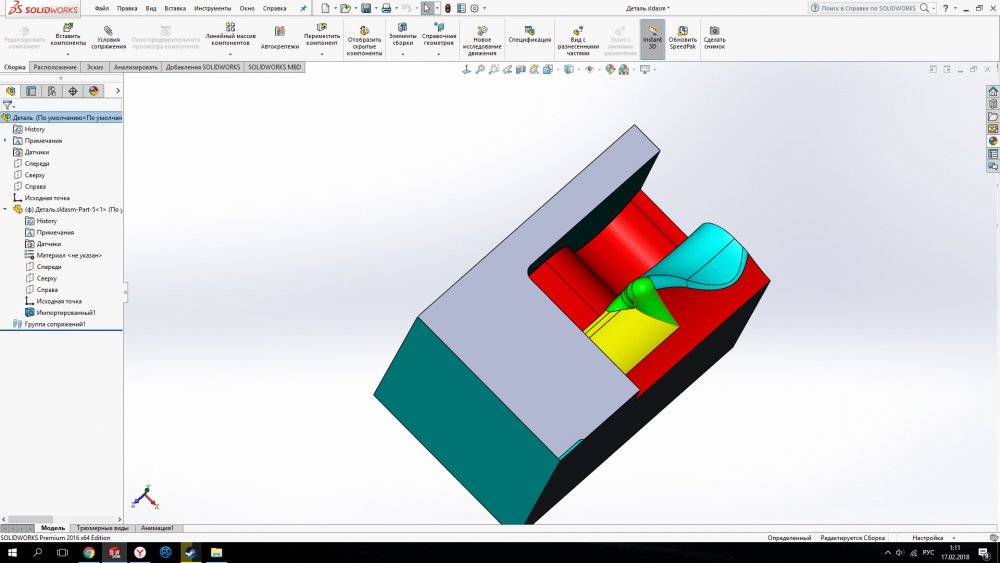
Metal 3D printing. Applications
GE LEAP aircraft engine parts 3D printed at Avio Aero (Photo: GE)
There are several industries already using 3D printers to make everyday objects - you may not even know that these objects are printed.
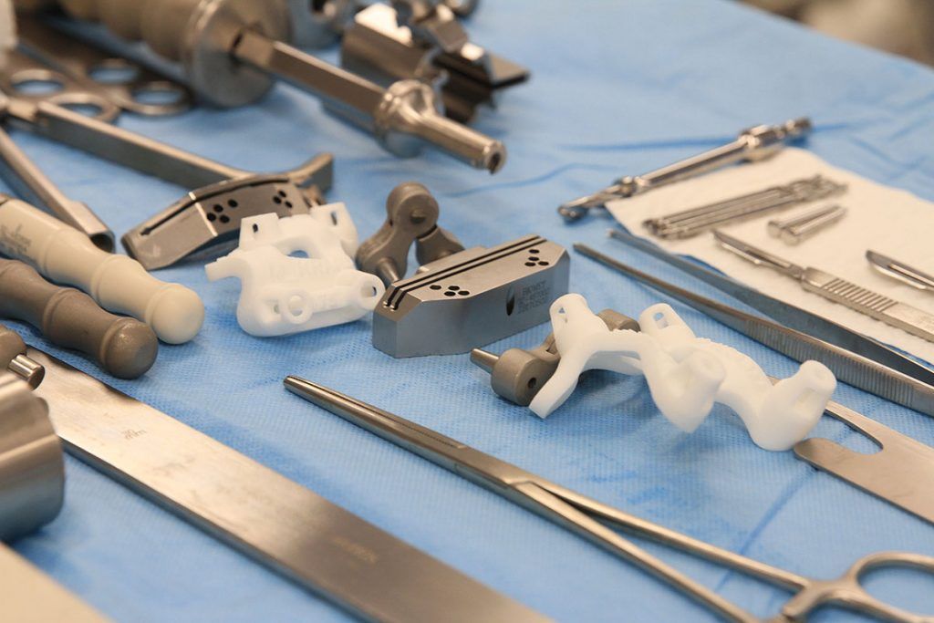
- The most common case is surgical and dental implants, which are considered the best option for patients today. Reason: they can be tailored to individual needs.
- Another industry is jewelry. Here, most manufacturers have abandoned resin 3D printing and wax casting, switching directly to metal 3D printing.
- In addition, the aerospace industry is becoming more and more dependent on 3D printed metal objects. The Italian company Ge-AvioAero was the first to do all-metal 3D printing. It manufactures components for LEAP aircraft engines.
- Another industry targeting metal 3D printing is the automotive industry. BMW, Audi, FCA are seriously considering this technology, not only for prototyping (3D printing has been used for this for quite some time), but also for making real parts.
Before metal 3D printing really takes off, however, there are some hurdles to overcome. And first of all, this is a high price, which cannot be made lower than during molding. Another problem is the low production speed.
Metal 3D printing.
Technologies
Most metal 3D printing processes start with an “atomized” powder
You can talk a lot about “metal” 3D printers, but their main problems remain the same as any other 3D – printers: software and hardware limitations, material optimization and multimateriality. We won't talk too much about the software, we'll just say that most of the major specialized software companies, such as Autodesk, SolidWorks and solidThinking, try to emphasize as much as possible the fact that as a result of the 3D metal printing process, you can get any shape you want.
In general, printed metal parts can be as strong as parts made by traditional processes.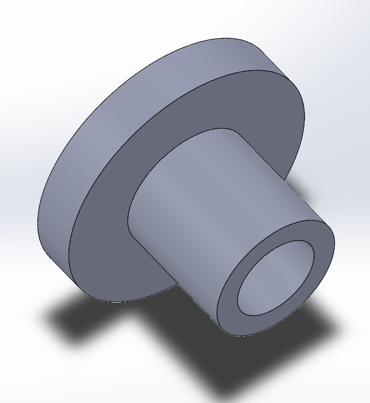 Parts made using DMLS technology have mechanical properties equivalent to casting. In addition, the porosity of objects made on a good "metal" 3D printer can reach 99.5%. In fact, manufacturer Stratasys claims that 3D printed metal parts perform above industry standards when tested for density.
3D printed metal can have different resolutions. At the highest resolution, layer thickness is 0.0008 - 0.0012" and X/Y resolution is 0.012 - 0.016". The minimum hole diameter is 0.035 - 0.045". formed layer)
The metal 3D printing process used by most relevant large companies today is called Powder Bed Fusion. This name indicates that some source of energy (a laser or other energy beam) melts an "atomized" powder (i.e., a metal powder that is carefully ground into spherical particles), resulting in layers of a printed object.
There are eight major manufacturers of metal 3D printers in the world that already use this technology; while we are talking here, there are more and more such companies. Most of them are in Germany. Their technologies are called SLM (Selective Laser Melting - selective laser fusion) or DMLS (Direct Metal Laser Sintering - direct metal laser sintering).
Metal 3D-printing process No. 2:
Binder Jetting (spraying the binder)
under 3DP technology EXONE Metal objects are printed due : ExOne)
Another professional approach that also uses a powder base is called Binder Jetting. In this case, the layers are formed by gluing metal particles together and then sintering (or fusing) them in a high-temperature furnace, just like it is done with ceramics.
Another option, which is similar to working with ceramics, is mixing metal powder into metal paste. A pneumatically extruded 3D printer (similar to a syringe bioprinter or an inexpensive food printer) forms 3D objects. When the required shape is reached, the object is sent to the furnace, i.e. in the mountains
This approach is used in the Mini Metal Maker, apparently the only inexpensive "metal" 3D printer.
Metal 3D printing process #3: 9Metal Deposition This is not entirely true. Of course, on some desktop device, simply fusing metal threads onto the base will not work. However, very large steel companies can do it. And they do. There are two options for working with "metal surfacing".
One is called DED (Directed Energy Deposition) or Laser Cladding. Here, a laser beam is used to melt the metal powder, which is slowly released and solidifies as a layer, and the powder is fed using a robotic arm.
Normally the whole process takes place in a closed chamber, but the MX3D project used conventional 3D printing techniques to build a full-size bridge. Another option for metal fusion is called EBAM (Electron Beam Additive Manufacturing - additive electron beam technology), which is essentially soldering, in which a very powerful electron beam is used to melt 3 mm titanium wire, and the molten metal forms very large finished structures. As for this technology, its details are known so far only to the military.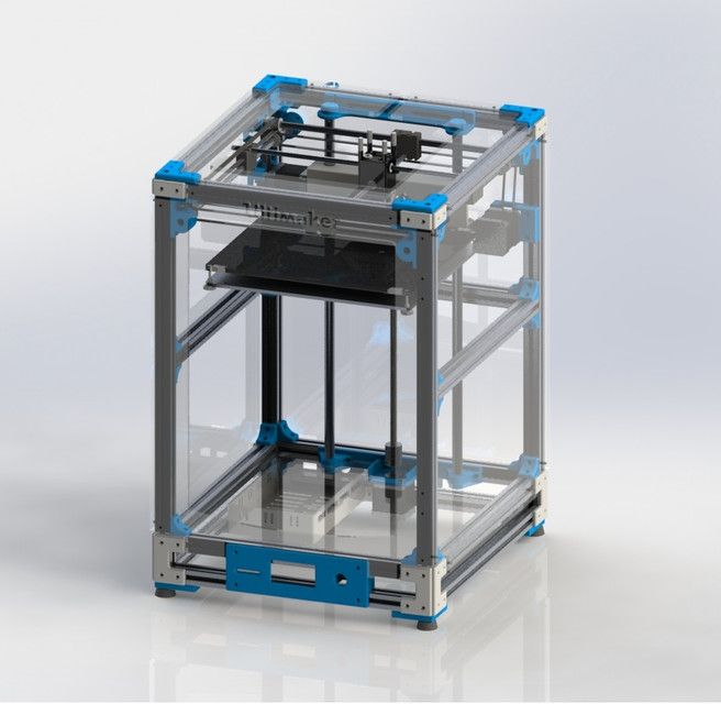
Metallic 3D printing. Metals
3D Printing Metal #1: Titanium
Pure titanium (Ti64 or TiAl4V) is one of the most commonly used metals for 3D printing and is definitely one of the most versatile, strong and lightweight. Titanium is used both in the melting process in a preformed layer and in the process of spraying a binder and is used mainly in the medical industry (for the manufacture of personal prostheses), as well as in the aerospace industry, automotive and machine tools (for the manufacture of parts and prototypes). But there is one problem. Titanium is very reactive and explodes easily in powder form. Therefore, it is necessary that titanium 3D printing takes place in a vacuum or in an argon environment.
3D printing metal #2: Stainless steel
Stainless steel is one of the cheapest 3D printing metals. At the same time, it is very durable and can be used in a wide range of manufacturing and even artistic and design applications. The type of steel alloy used also contains cobalt and nickel, is very difficult to break, and has a very high elasticity. Stainless steel is used almost exclusively in industry.
3D Printing Metal #3: Inconel
Inconel is a superalloy manufactured by Special Metals Corporation and is a registered trademark. The alloy consists mainly of nickel and chromium and is very heat resistant. Therefore, it is used in the oil, chemical and aerospace (for black boxes) industries.
3D Printing Metal #4: Aluminum
Due to its lightness and versatility, aluminum is very popular in 3D printing. Aluminum alloys are commonly used.
3D Printing Metal #5: Cobalt Chrome
gap). It is most commonly used in the manufacture of turbines, dental and orthopedic implants, where 3D printing has become the dominant technology.
3D printing metal #5. Copper and bronze
With some exceptions, copper and bronze are used in wax melting processes, rarely in layer melting. The fact is that these metals are not very suitable for industry, they are more often used in the manufacture of works of art and crafts. ColorFabb offers both metals as the basis for a special metal filament.
3D printing metal #6. Iron
Iron, incl. magnetic, also mainly used as an additive to PLA-based filaments, which are produced, for example, by ProtoPasta and TreeD.
3D printing metal #7. Gold, Silver, and Other Precious Metals
Most preformed layer companies can 3D print precious metals such as gold, silver, and platinum. Here, along with the preservation of the aesthetic properties of materials, it is important to achieve optimization of work with expensive starting powder. Precious metal 3D printing is required for jewelry, medical applications and electronics.
Metallic 3D printing. Printers
Do not hesitate - the purchase of a metal 3D printer will not pass without a trace on your budget. It will cost at least 100-250 thousand dollars. Here is a list of a variety of "metal" printers, some of which can be found in firms providing 3D printing services.
Metal 3D Printer #1:
Sciaky EBAM 300 - Metal Filament Printing
If you need to print really large metal structures, Sciaky's EBAM technology is your best bet. By order, the device can be built in almost any size. This technique is used mainly in the aerospace industry and the military.
Sciaky's largest production printer is the EBAM 300. It prints objects in a volume of 5791 x 1219 x 1219 mm.
The company claims the EBAM 300 is also one of the fastest industrial 3D printers on the market. A three-meter-sized titanium part for an aircraft is printed on it in 48 hours, while the material consumption is about 7 kg per hour. In general, forged parts that usually take 6-12 months to complete can be made in 2 days with this 3D printer.
The metal layers are first cut and then ultrasonically welded. The largest Fabrisonic 7200 printer operates in a volume of 2 x 2 x 1.5 m. The metal powder 3D printer is the Concept Laser XLine 1000. It has a modeling volume of 630 x 400 x 500 mm and is the size of a house.
Its German company, one of the main suppliers of 3D printers for aerospace giants like Airbus, recently introduced a new machine, the Xline 2000.
This machine uses two lasers and has a working volume of 800 x 400 x 500 mm. Uses LaserCUSING laser technology (a variant of selective laser fusion) from Concept Laser, which allows you to print alloys of steel, aluminum, nickel, titanium, precious metals and even some pure substances (titanium and stainless steel).
Metallic 3D printing. Services
There are more than 100 companies worldwide offering metal 3D printing services. We list the most popular services for consumer needs.
Metal 3D Printing Service #1: Shapeways
The world's most popular 3D printing service, Shapeways offers two types of services. As a consumer, you can choose from a wide range of professionally designed objects, customize them, and then have them printed to your specifications. Like other 3D printing services, Shapeways offers a platform for designers to sell and print their work. Shapeways is also a good place for rapid prototyping: customers benefit from industrial-grade printers (EOS, 3D Systems) and personal technical support.
3D printing metals: aluminium, brass, bronze, gold, platinum, precious metal plating, silver, steel. There are also wax molds for jewelry purposes.
Metal 3D Printing Service #2: Sculpteo
Like Shapeways and i.materialise, Sculpteo is an online 3D printing service that allows anyone to upload 3D models and send them to fabrication in a wide range of materials . Like its competitors, Sculpteo provides a platform for hobbyists and professionals to showcase and sell their designs. The stable of Sculpteo printers includes highly professional machines from 3D Systems, EOS, Stratasys and ZCorp. Extensive technical documentation will help identify design flaws and select the right material for the project.
Metals for 3D printing: alumide (plastic with aluminum particles), brass, silver.
Metal 3D Printing Service #3: iMaterialise
Materialise is a company that works with industrial customers to prototyp 3D printed products. For casual users and designers, Materialize offers an online 3D printing service called i.materialise. As with Shapeways, this service allows anyone to upload their 3D designs and print them out. Once an object has been uploaded and successfully printed, a designer can list it for sale either in the gallery of the i.materalise online store or by embedding some code into their site.
3D printing metals: alumide (plastic with aluminum powder), brass, bronze, copper, gold, silver, steel, titanium.
Metal 3D Printing Service #4: 3D Hubs
Through 3D Hubs, you can search for individuals and companies that offer 3D printing services in your area, upload STL files (which are immediately evaluated for defects ) and contact service providers directly to get the job done. The online 3D printing service also allows you to sort offers by materials, customer rating, distance and many other parameters. Whatever object you wish to print, there is likely to be someone nearby who can print it. A significant number of materials can be printed in industrial quality, such materials have an HD mark in the search field.
3D printing metals: aluminium, bronze, cobalt-chromium, stainless steel, titanium.
FDM 3D printer
- 1 Description
- 2 General process
- 3 Structural elements
- 3.1 Body
- 3.2 Extruder
- 3.3 Working platform
- 4 Preparing digital model
- 5 Seal
- 6 Application
Description
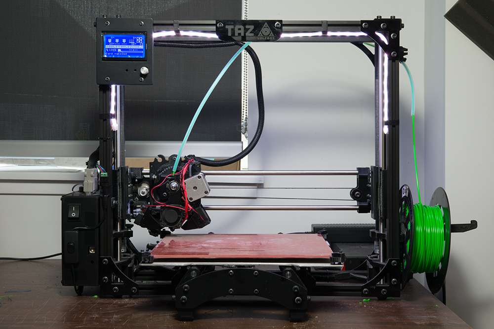
Fused Deposition Printing (FDM) technology has become widespread among individuals and small businesses due to its wide range of features, relative simplicity and good affordability. The popularity of this method deserves a more detailed description of the process and the printers used. In this section, we will look at the nuances of the design of printers and the application of technology in practice.
General process
Like all 3D printing methods, FDM belongs to additive manufacturing technologies. The term "additive" is an Anglicism from the word "additive", meaning "addition" or "by addition". The term is intended to separate technologies for the production of complex three-dimensional products that differ from the usual "subtractive" ("subtractive" - "due to separation") methods - milling, drilling, grinding, etc.
FDM can be considered one of the most technologically simple 3D printing methods. The process is based on the successive layering of a thin thread of molten plastic up to the creation of a solid three-dimensional object. A plastic thread wound on a spool is used as a consumable. Occasionally, individual bars of plastic are used. The standard thread diameter is 1.75mm or 3mm.
The printing process consists of a number of steps:
- Create or import a digital 3D model
- Processing a digital model for printing with the addition of supporting structures
- Location and orientation of the digital model on the desktop
- Slicing - cutting a digital model into separate layers with data conversion into instructions for the printer, called the G-code
- Directly print
- If necessary, physical or chemical treatment of the finished model
Structural elements
Enclosure
Ultimaker 3D Printer with open wooden enclosure
Many elements are important in the construction of an FDM 3D printer that are not always obvious to the inexperienced person. So, the material of the case matters in the event that it carries the load. Many FDM printers are available with wooden cases - this solution seems cheap and unsightly, but in fact it helps to absorb vibrations during printing, which has a positive effect on the quality of the manufactured models.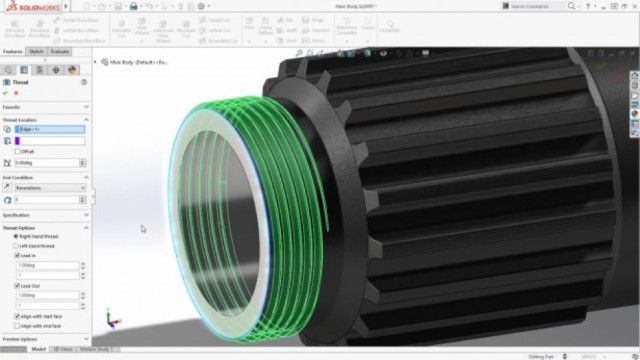 On the other hand, a steel or aluminum frame ensures the durability and impact resistance of the device.
The open or closed design of the printer also matters. A well-ventilated working chamber is useful when printing with polylactide (aka PLA plastic), as this material vitrifies for a long time. If the printed layers do not have time to solidify and seize, they may spread, or deformation of the underlying layers under the pressure of the upper ones.
On the other hand, many popular materials (such as ABS and nylon) have a high degree of shrinkage. By "shrinkage" is meant the reduction in volume of the material as it cools. In the case of the same ABS plastic, excessively fast and uneven cooling of the applied layers can lead to their twisting, or deformation and cracking of the model as a whole.
PICASO Designer 3D printer with closed plastic case
In this case, the case with closed cladding comes in handy, allowing you to achieve slow, uniform cooling of the material.
Finally, the shape of the FDM printer can also be linked to the coordinate system used.
Thus, the most popular option is the Cartesian or, more accurately in most cases, rectangular coordinate system.
Recently delta coordinate systems are gaining popularity - such devices are called "delta robots" and offer certain benefits in terms of printing accuracy and ease of expanding the vertical size of the construction area.
Structural elements and rails are usually made of aluminum or steel. The extruder and platform are driven by belts or screws.
Partially disassembled 3DPrintBox printer extruder. You can clearly see the pink plastic thread and the pulling mechanism - two gears with grooves in the teeth
Extruder
The next important element is the extruder, that is, the printer's print head. These devices may vary in design, but generally contain the same basic components:
- Nozzle feeder
- Nozzle used to melt the filament and extrude the molten material
- Heating element for heated nozzle
- Fan
As a rule, the pulling mechanism consists of gears or screws driven by an electric motor.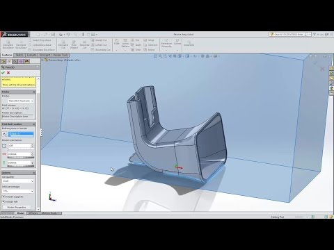
Obviously, the electric motor drives the gears to feed the filament into the nozzle. In the nozzle, the thread is melted, followed by extrusion of a viscous material.
An extremely important point is the sharp temperature gradient between the bottom and top of the nozzle - for this purpose the fan is installed.
At the transition of the glass transition temperature, the plastic becomes soft, but not yet viscous, expanding in volume.
3DPrintBox extruder assembled. The electric motor of the traction mechanism is visible (top), double fan (middle) and nozzle with attached electric heating element (bottom)
In this state, the friction of the material with the inner walls of the nozzle increases.
If the length (and, as a result, the area) of this section is too large, then the total coefficient of friction may become unbearable for the pulling mechanism.
Thus, the length of the nozzle section with unmelted filament and the length of the section with molten material do not really matter, but the length of the plastic section at the glass transition temperature should be as short as possible.
The most effective solution to this problem is the use of heat sinks and fans to cool the filament and the top of the nozzle.
In fairness, the residence time of the plastic in the molten state should also be minimized, since many thermoplastics lose their plasticity after prolonged exposure to high temperatures, and the resulting solids can clog the nozzle.
Diagram of the transition of a plastic filament from a solid to a viscous state. The length of the middle section should be as short as possible to prevent problems with material push through
Typically, this kind of problem does not occur in normal, stable extrusion because the nozzle length is too short.
Clogging of the nozzle can occur due to internal irregularities or errors in the manufacture of the thread: the resulting stagnation leads to the gradual formation of grains, which are then carried away by the flow of molten plastic and clog the outlet.
The most common nozzle materials are aluminum and brass.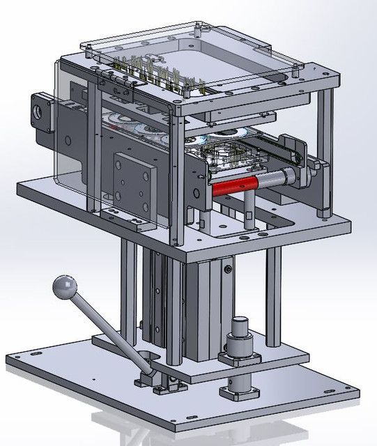
Hole diameter may vary, but average is 0.3mm.
Smaller bores allow for higher resolution, while larger bores increase build speed and reduce the risk of nozzle clogging.
Work platform
The 3D Systems Cube 3D printer platform moves in the X and Z axes, and the extruder moves in the Y axis
The work platform serves as a surface for building models.
Depending on the coordinate system used, the platform can be movable or static.
Typically, in printers using the Cartesian coordinate system, the movement of the platform in the vertical plane is responsible for the vertical positioning of the extruder relative to the platform itself.
Some models also add movement of the platform along one of the axes in the horizontal plane, which allows you to slightly reduce the dimensions of the device, provided that the case is open.
An example of such printers is the popular 3D Systems Cube.
The delta robot work platform remains in place. Positioning of the extruder in three planes is carried out solely by the movement of three manipulators
Delta printers ("delta robots") use static platforms.
The positioning of the print head in all three dimensions is carried out exclusively by the movement of the extruder itself.
As a rule, the extruder is suspended on three manipulators, whose coordinated movement along vertical guides moves the die.
Asymmetrical movement controls the positioning of the extruder horizontally by changing the angle of the manipulators, and symmetrical movement - vertically.
Alternatively, a movable platform and a stationary extruder can be used, but these designs are not yet widely used.
Experimental Quantum Delta Printer uses "inverted" design with moving bed and stationary extruder
A distinctive feature of all Delta printers is the cylindrical shape of the build area.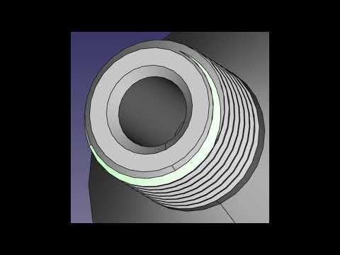 One of the advantages of such designs is the ease of building up the working area. So, to increase the height of the building, you only need to install guides and cables of increased length.
However, even static platforms cannot be called completely immobile. Before starting printing, platform calibration is required, that is, the elimination of a possible tilt. Calibration mechanisms can be either manual or automatic, depending on the printer model.
In the case of manual calibration, the user will be required to sequentially position the nozzle at different points on the platform.
To measure the distance, special templates are used, and in the cases of the most simple or home-made designs, simply sheets of office paper, whose thickness corresponds approximately to 100 microns.
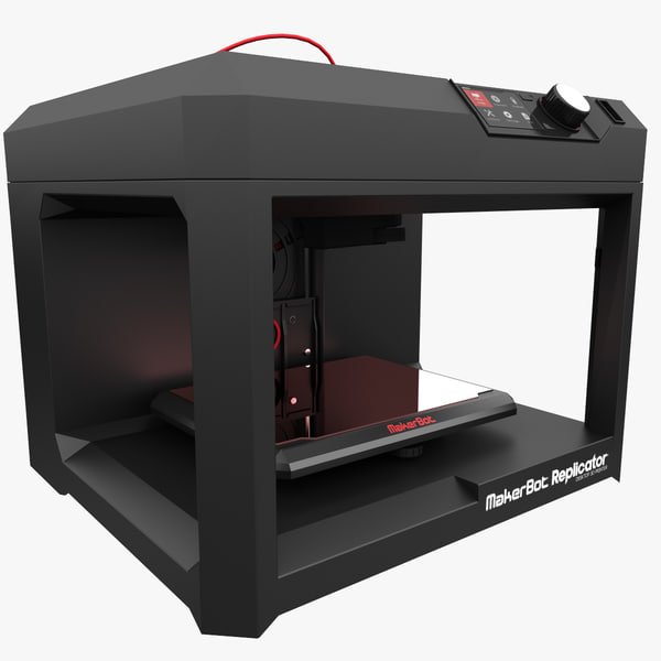
More advanced devices like the MakerBot Replicator use special sensors to accurately measure distance. Tilt adjustment is made by rotating the spring-loaded screws on which the platform rests.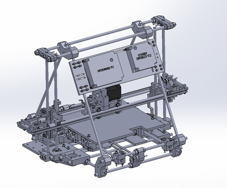
Calibration of the platform is often done with adjustment screws, although most printers help with this task by moving the extruder in succession to different points on the platform.
If the nozzle height is too low, extrusion will simply not occur.
If too large, the filament will not adhere to the surface and the printer will print "in the air", creating intricate filaments that have nothing to do with the given model.
The result of platform tilt can be a combination of these two effects. No matter how perfect the design of the printer, users are encouraged to trace the construction of the first few layers of the model.
Perforated printer worktable Up! Plus 2 provides good adhesion of plastic to the surface, but requires careful maintenance, as the holes are easily clogged
Depending on the design, the working platform can be equipped with a removable table.
This solution is often used in printers with closed housings that make it difficult to remove models from the platform or clean the surface.
In the case of perforated tables, this solution is simply necessary, since the surface is cleaned by soaking in solvents.
The disadvantage of removable tables is the possibility of play if the fasteners or clamps are sufficiently weak.
Heated aluminum platform with removable glass worktable for PICASO Designer 9 printer0525
When printing on certain materials such as ABS or nylon, the bed is equipped with a heating element. The purpose of the heating is to slow down the cooling of the lower layers in order to prevent their twisting caused by the shrinkage of the thermoplastic. You can read more about this phenomenon and methods of struggle in the section "How to avoid deformation of models during 3D printing".
The materials used to make work tables are very diverse. Among them, aluminum, steel, acrylic can be mentioned - the presence of heating, of course, narrows the choice of materials. Glass has recently become a popular choice due to its high resistance to deformation and the ease of achieving a perfectly flat surface during production.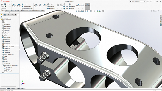 Some manufacturers even use volcanic glass because of the low thermal conductivity, which slows down the cooling of the initial layers of the model.
Preparing the digital model
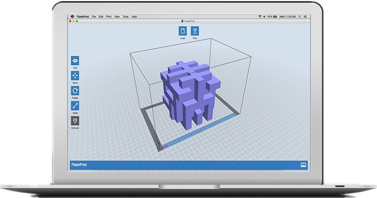
Popular open source slicer ReplicatorG
Creating digital 3D models is not part of the 3D printing process. To create models, conventional computer-aided design systems (“CAD” or “CAD” in English terminology) are used, including 3D editors such as SolidWorks, AutoCad and LightWave, among many.
The process of preparing a model for printing begins with importing a 3D model in .STL format into a special program called a slicer. Such programs perform the functions of graphical editors, allowing you to add reference elements necessary to support model attachments. Many slicers allow you to add support structures automatically without requiring any effort on the part of the user. In addition, slicers allow you to place models on the desktop and change their spatial orientation.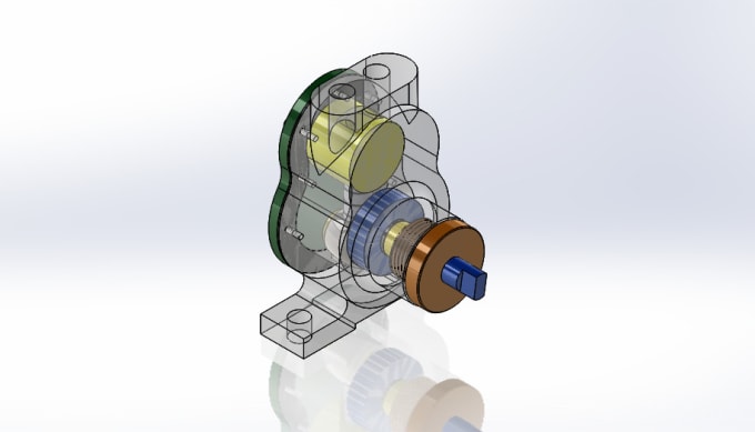
Advanced programs also allow you to change fine print settings - the thickness of the applied layer, nozzle temperature, take into account the consumable used.
The capabilities of slicers are closely related to the capabilities of the printers themselves. Some models have a "closed code" that requires the use of branded slicers. Some of the more popular open source slicers include Repetier-Host, ReplicatorG, and Skeinforge.
Building model support structures in Repetier-Host 9 slicer0525
After the digital model is placed on the virtual desktop, the necessary supports are created and the settings are made, slicing is performed directly - cutting the three-dimensional model into virtual layers with a thickness corresponding to the thickness of the applied plastic layers. Each such section will serve as a template for building a specific layer of the physical model. The end result is provided in the form of a G-code, a set of commands for a 3D printer that determines the movement of the extruder and platform during the printing process.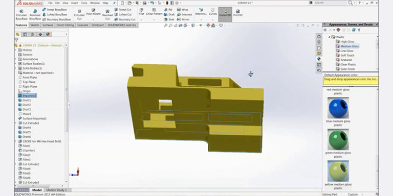 G-code can be transferred directly from a computer using a direct connection, or written to a memory card or USB stick for offline printing, provided that the printer is equipped with the necessary interface and control module.
Printing
Some 3D printing enthusiasts make their own scrapers to remove finished models from the worktable
Printing can take quite a long time, often in the hours. The duration depends on the speed of printing and the size of the models being produced. Print speed, in turn, depends on the complexity of the model, the perfection of positioning algorithms, layer thickness and nozzle diameter. Interrupting the printing process may result in the loss of the model. Although some printers allow you to temporarily stop the process to replace the consumable, a long pause will cause the upper layers to cool. When printing is resumed, subsequent layers may not "grab" with those already printed.
Thin scrapers are used to remove finished models from the table. At the same time, it is recommended to wait for at least partial cooling of the model in order to avoid damage to still soft layers or burns when touching still hot plastic. In addition, if you have enough patience, you can wait for complete cooling and shrinkage, which in most cases automatically leads to the separation of the model from the table.
Demonstration of support structures as part of the finished model
Depending on the working plastic, mechanical or chemical processing may be possible. Thus, models made of ABS plastic can be processed with acetone vapor, which leads to smoothing of roughness and printed artifacts, but can also lead to the loss of the most delicate features of the model. Basically, processing is reduced to the removal of supporting structures of hinged elements of the model. When printing on printers with a single extruder, the supports are made of the same material as the model itself, complicating the process somewhat. When using printers with two or more print heads, it is possible to build supports using water-soluble polyvinyl alcohol (PVA plastic). For more information on the plastics used in FDM 3D printing, see the FDM Consumables section.
Applications
3D printed controller prototypes for the Xbox One game console
The relative cheapness of FDM printers and consumables makes this technology widely popular. First of all, such devices are used for rapid prototyping. Various plastics allow you to create functional models of various products. Thus, ABS plastic, which is popular in FDM printing, is widely used in the mass production of various household products, automotive parts, tools, toys, souvenirs, etc. The sufficiently high accuracy of 3D printing makes it possible to obtain functional prototypes that practically do not differ in workmanship from traditional cast products.
The MakerBot Mini 3D Printer was designed for home and educational use
This application of technology allows for significant savings in the development of new designs. Microsoft used 3D printing to create about 200 prototypes of the Xbox One controller, while Dell placed an order for 5,000 M200 FDM printers from Poland's Zortrax for use in affiliates around the world.
Although the productivity of FDM 3D printing is quite low, the relative cheapness allows the use of FDM printers for the production of small batches of finished products - souvenirs, toys, etc.
Improvement in technology and a significant reduction in the cost of devices allows FDM printers to gradually take root in everyday life. The benefits of 3D printing at home are clear—even fairly simple devices are capable of producing household appliances or broken plastic parts as needed. The cost of home production already makes such an application profitable in comparison with the purchase of finished products. The only significant obstacle to the widespread adoption of 3D printers in everyday life can be considered the reluctance of most people to go into the details of three-dimensional digital design. This barrier is gradually being eroded with popular services such as Thingiverse, Shapeways and Cubify offering a variety of print-ready 3D designs. Many of the available digital models are provided free of charge.
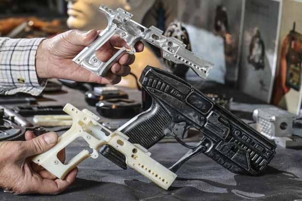
The 3D printed Liberator pistol called into question the ability of government agencies to regulate firearms
The Liberator pistol made a lot of noise. The design of this weapon includes one single metal element - the striker, which can be used as an ordinary nail. All other design elements can be printed. The design of the pistol has been released to the public.
Finally, the development of FDM 3D printing allows the development of an entire industry of 3D design and print-to-order. 3D boutiques are already becoming commonplace in many countries. The further spread of FDM printing technology may lead to a restructuring of the global economy: as home production grows, the demand for finished products will fall in parallel with the growth in demand for consumables.