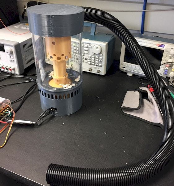
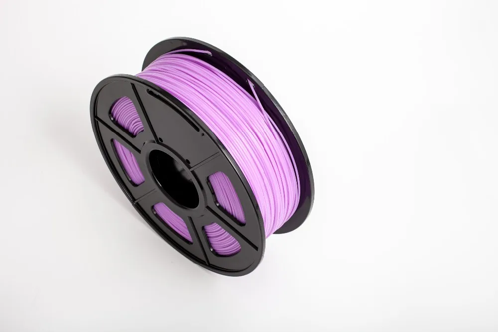
Electrifi conductive 3d printing filament
How to print with Electrifi
This tutorial demonstrates how to print electric circuits with Electrifi filament on a typical fused deposition modeling (FDM) desktop 3D printer.
Step 1: Modify the extruder (if necessary)
The Electrifi conductive filament can be printed without any modification of your extruder if the gap between the hobbed gear and the hot end is sufficiently small. Figure 1 shows the filament gets kinked between the gear and hotend if the gap is too large (> 8 mm in this case). This issue can be corrected by inserting a longer Teflon tube (OD = 4 mm and ID = 2 mm) into the hot end barrel to fill the gap. We suggest trying to print Electrify with your printer first, and if this kinking problem happens try replacing your current teflon tube with a longer one.
Figure 1 Left: The Electrifi filament is kinked below the hobbed gear. Right: The Electrifi filament is pushed straight through with the support from the Teflon tube.
Step 2: Set the Z-height
For printing Electrifi, we recommend calibrating your printer's Z-axis such that the distance between the nozzle and the bed is around 0. 1 mm. Please see your 3D printer's manual for calibration instructions. A standard piece of A4 paper (approximately 0.1 mm thick) can be used as a guide. When slipping the piece of paper between the nozzle and the print bed you should feel the paper drag against the nozzle as you try to pull the paper out. Once the printer is calibrated, you can print on different substrates by changing the Z-offset in your 3D printer software (assuming this setting is available). For Cura, the Z-offset setting can be found under Machine/Machine Settings (Note: we are using the LulzBot edition of Cura, version 17.10). For example, to print on 5-mm-thick foam board, set the Z-offset to 5 mm prior to converting your stl file to gcode. For any substrate, make sure it is taped down to the printer bed so its flat and doesn’t move around.
Figure 2. Left: The extruder is at the Home position 0.1 mm from the print bed. Right: The substrate (black foam board) is taped flat to the print bed.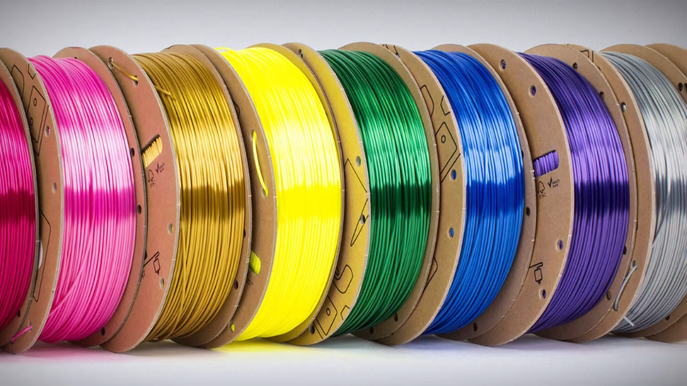
Step 3: Print with Cura
We recommend Cura for slicing and 3D printing because its free, open source, and user friendly. We have optimized a print profile for use with Cura on a Prusa I3 printer. To use the print profile, download and unzip the file, and go to File/Open Profile to load the file into Cura. With our profile settings, it takes 7 minutes to print the circuit shown in Figure 3 (83 mm × 37 mm × 0.5 mm) using a 0.4 mm nozzle, or you can increase the shell thickness to 0.9 mm and nozzle size to 1 mm in order to print the circuit in <4 minutes (see the time lapse video below). Download the stl file below to try it yourself! Note that the Cura profile does not change the Z-Offset, so double check that you have the correct Z-Offset for you substrate before printing.
In our next tutorial, we will turn this circuit into an LED nametag.
Download "cura_electrifi_print_profile"
Download LED_nametag stl file
Figure 3. A 3D printed LED nametag circuit on black foam board.
All About Conductive PLA 3D Printing Filament: Materials, Properties, Definition
Resources3D Printing DesignAll About Conductive PLA 3D Printing Filament: Materials, Properties, Definition
Learn about conductive PLA 3D printing filament and how it's used in manufacturing.
By Team Xometry
September 19, 2022
8 min read
RECENT STORIES
Video: 10 Design Tips for Sheet Metal Bending
December 16, 2022
4 min read
10 Best Metal 3D Printers: Buyer's Guide
December 16, 2022
11 min read
What Are Counterbore Holes in Machining?
December 16, 2022
6 min read
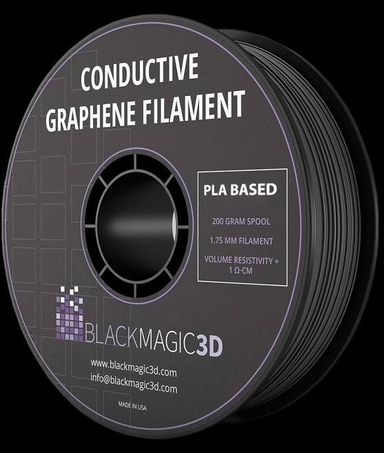
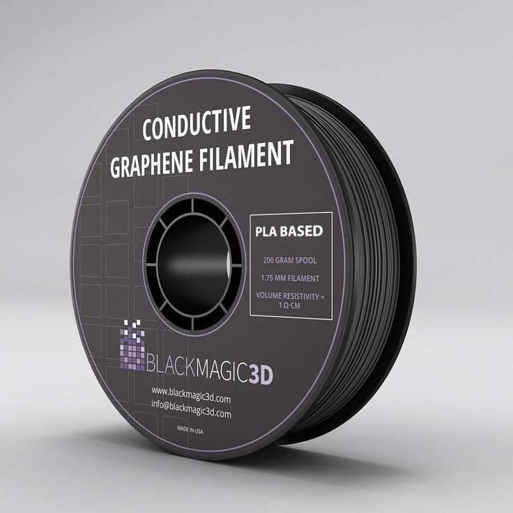
Conductive PLA (Polylactic Acid) is a 3D printing material specifically designed to transmit electric current. This property allows the manufacture of parts with integrated electrical circuits or anti-static enclosures for use with sensitive electronics. The first graphene-infused PLA filament was developed by Graphene 3D Lab in 2015. Graphene 3D Lab has since changed its name to G6 Materials.
Conductive PLA is a low-cost way of powering low voltage (0 to 60 V) electronic devices while also maintaining some of the mechanical strength of PLA. The additives do, however, negatively affect the mechanical properties of the PLA to some degree. Printing with conductive PLA requires no special processes. The same settings that are used for standard PLA can be used for conductive PLA. A typical resistivity for conductive PLA is 0.6 Ω-cm. The main advantages of conductive PLA are its low cost and ease of use. Some typical applications are shown in Figure 1 below:
Slide 1 of 1
A variety of conductive PLA printed parts.
Image Credit: www.3dinsider.com/Types of 3D Printer Filaments
What is Conductive PLA 3D Printing?
Conductive PLA (Polylactic Acid) 3D printing filament refers to PLA filament that is able to transmit electrical current.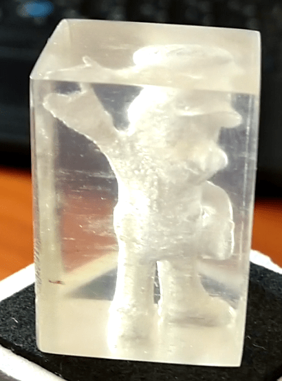 Conductive PLA is one of the most popular conductive filaments due to its ease of use and relatively low cost. According to a recent study, conductive PLA shows promise in the development of sensors for use in wearable electronics.
What is the Composition of Conductive PLA Filament?
Conductive PLA 3D printing filament is made by mixing conductive additives into the PLA base polymer. These additives make standard PLA slightly conductive. Some of the common additives are listed below:
- Carbon Black: Carbon black is powdered carbon that is often used as a pigment. However, when a specific grade of carbon black is mixed in with PLA, the conductivity of the composite filament material is increased. Carbon black is the cheapest form of conductive PLA 3D printing filament.
- Graphene: Graphene is a planar sheet of carbon atoms arranged in a hexagonal pattern. The arrangement of the carbon atoms means that each atom has one free electron, which aids in the transmission of current.
- Metal-filled: Metal powder like copper or bronze can be mixed into the PLA to increase conductivity. Metal-filled PLA has some of the best conductivity ratings.
What are the Properties of Conductive PLA Filament?
Polylactic Acid (PLA) is one of the most popular 3D printing filaments due to its low cost and ease of use. PLA is a semicrystalline thermoplastic. Its partially ordered molecular structure gives it a distinct melting point, unlike amorphous polymers, which have no such distinct phase transition. Listed below are some common properties of conductive PLA 3D printing filament:
- The percentage of conductive PLA particles added to the base polymer is typically up to 80% by volume.
- The resistivity of the material on a part’s XY plane, i.e. parallel with the bed plate is typically up to 30 Ω-cm.
- The resistivity of the material along a parts’ Z axis, i.e. parallel with the bed plate is typically up to 115 Ω-cm.
- The maximum safe current that can be transferred through the conductive PLA is typically up to 100 mA.
 The maximum safe voltage that can be applied across the PLA is typically up to 60 V.
 - The resistance of a 10 cm length of 1.75 mm diameter filament is typically between 2000 and 3000 Ω.
Comparison of Conductive PLA Filament Properties
The properties of some common conductive PLA 3D printing filaments are listed in Table 1 below:
Table 1: Comparison of Different Brands of Conductive PLA
| Property | Protopasta Conductive PLA | Electrifi Conductive Filament | Black Magic 3D (Conductive Graphene PLA Filament) |
|---|---|---|---|
Property Resistivity (Ω-cm) | Protopasta Conductive PLA 30 | Electrifi Conductive Filament 0.006 | Black Magic 3D (Conductive Graphene PLA Filament) 0.6 |
What are the Limitations of 3D Printing with Conductive PLA?
Conductive PLA 3D printing filament is a popular choice for experimenting with electrical applications. However, there are some shortcomings that need to be understood prior to using the material. The key challenges to using conductive PLA filament are listed below:
- Conductive PLA is still not very conductive, despite its name. These materials offer a small amount of conductivity for special applications but are not meant to efficiently transfer electrical current. Nothing is better than a metal conductor like a copper wire.
- The addition of additives like carbon black, graphene, or metal powder will increase the brittleness of PLA. PLA is already classified as a brittle material, and conductive PLA will be even more susceptible to cracking when subjected to impact loading.
- Only low-voltage components can be powered through conductive PLA. This characteristic considerably limits the potential applications of the material.
- A part printed with electrically conductive PLA 3D printer filament will have lower conductivity along the z-axis due to the fact that the individual part layers are not as seamlessly bonded to each other as the material within a particular layer.

One big advantage of conductive PLA 3D printing filament is that it has ESD (Electrostatic Dissipative) properties. This property means that it does not allow a static charge to build up on its surface.
Why is Conductive PLA Used in 3D Printing?
Conductive PLA filament is mainly used for a range of low-voltage electrical applications, some of which are listed below:
- Conductive PLA 3D printing filament can be used to create parts that can transmit current through their structure without the need for electrical cabling. However, this application is limited to low-power applications like powering an LED light.
- Conductive PLA 3D printing filament can be used for electromagnetic and radio wave shielding to eliminate the interference of other signals on sensitive electronic equipment. This type of interference can produce erroneous readings which can skew scientific results.
- One of the best uses for conductive PLA is for capacitive sensors, i.
 e., sensors that respond to touch. These are low-power applications that do not require high levels of conductivity.
How to Use Conductive PLA in 3D Printing
Printing with conductive PLA (Polylactic Acid) 3D printing filament is generally as simple as printing with standard PLA, with a few special requirements. These requirements are listed below:
- Carbon-filled conductive PLA is very abrasive. Therefore, a hardened steel nozzle is recommended.
- Conductive PLA is very brittle. Therefore, it is important to ensure that the filament is guided to the nozzle as gently as possible. Any sharp bends will snap the filament.
What are the Best Configuration Settings for Conductive PLA 3D Printing?
The specific settings to use when printing with conductive PLA 3D printing filament depends on the filament brand. However, some general guidelines for printing with conductive PLA filament are listed in Table 2 below:
Table 2: Conductive PLA Printer Settings
| Printer Setting | Value |
|---|---|
Printer Setting Extruder/Nozzle temperature | Value 215 °C |
Printer Setting Bed temperature | Value 60 °C |
Printer Setting Print speed | Value 25 and 45 mm/s (10 mm/s for metal filled) |
Printer Setting Flow of filament | Value 2 and 3 mm3/s |
Printer Setting Extrusion Width | Value 0. |
 45 mm
45 mmWhat is the Best Conductive PLA 3D Print Speed?
Conductive PLA 3D printing filament tends to be brittle. The filament can easily snap during high-speed printing maneuvers. It is therefore recommended to print at speeds as low as 10 mm/s for more complex printing tasks. This lowered print speed may take longer, but it will ensure a successful print.
What is the Melting Temperature of Conductive PLA Filament?
Typical melting temperature of conductive PLA is between 230-250 °C, but still varies based on brand. The extruder temperatures of various conductive PLA (Polylactic Acid) 3D printing filaments are listed in Table 3 below:
Table 3: Recommended Extruder Temperatures for Typical Conductive PLA 3D Printing Filaments
| Filament Type | Conductive PLA Filament Extruder Temperature (°C) |
|---|---|
Filament Type Protopasta Conductive PLA | Conductive PLA Filament Extruder Temperature (°C) 215 |
Filament Type Electrifi Metal-Filled Conductive PLA | Conductive PLA Filament Extruder Temperature (°C) 130 to 160 |
Filament Type Black Magic 3D Conductive Graphene PLA | Conductive PLA Filament Extruder Temperature (°C) 220 |
Filament Type Amolen Conductive PLA | Conductive PLA Filament Extruder Temperature (°C) 220 to 250 |
Is a Heated Printing Bed Required When Printing with Conductive PLA?
No, a heating bed is not strictly required for printing conductive PLA. However, for larger parts, it may be required to prevent warping.
What is a Good Wall Thickness for 3D Printing Conductive PLA?
The optimal wall thickness for a conductive PLA part depends on how the product will be used. If it is used for an ESD (electrostatic discharge) enclosure, a thicker wall thickness may be required to improve structural integrity. This requirement is because conductive PLA is structurally weaker than standard PLA. However, in general, a wall thickness of 1 mm will be good enough for most applications.
What is a Good Wall Density for 3D Printing Conductive PLA?
The infill density for conductive PLA is best kept at 100%, meaning the part is completely solid. A solid structure will more effectively transmit current. It may be therefore beneficial to print the conductive parts of a design separately to save on material as conductive PLA is more expensive than standard PLA.
What is the Difference Between Conductive PLA and ABS in 3D Printing?
Conductive PLA and conductive ABS (acrylonitrile butadiene styrene) will both transmit electric current in a similar matter. However, conductive ABS will have better toughness than conductive PLA.
Summary
This article presented conductive PLA 3D printing filament, explained what it is, and discussed all of the different factors to consider when using it. To learn more about conductive PLA 3D printing filament, contact a Xometry representative.
Xometry provides a wide range of manufacturing capabilities, including 3D printing and other value-added services for all of your prototyping and production needs. Visit our website to learn more or to request a free, no-obligation quote.
Disclaimer
The content appearing on this webpage is for informational purposes only. Xometry makes no representation or warranty of any kind, be it expressed or implied, as to the accuracy, completeness, or validity of the information. Any performance parameters, geometric tolerances, specific design features, quality and types of materials, or processes should not be inferred to represent what will be delivered by third-party suppliers or manufacturers through Xometry’s network. Buyers seeking quotes for parts are responsible for defining the specific requirements for those parts. Please refer to our terms and conditions for more information.
Team Xometry
This article was written by various Xometry contributors. Xometry is a leading resource on manufacturing with CNC machining, sheet metal fabrication, 3D printing, injection molding, urethane casting, and more.
3D printing and conductive threads create clothes with buttons
Engineers from the Netherlands and Canada have developed a method to create a two-layer garment with buttons integrated into the fabric. They suggested embroidering an electrical circuit with conductive threads and using a 3D printer to print plastic buttons on fabric with thin metal plates that complete the circuit. An article on the method was presented at the DIS 2020 conference.
There are quite a few attempts to create smart clothes: mostly research projects, although there are already commercial examples, such as the jacket from Google and Levi's. As a rule, they have the same, still unsolved, problem: it is difficult to make clothes with electronic components as flexible, stretchable and, as a result, comfortable to wear as regular jackets or sweatshirts. In particular, there is a problem with the buttons, so you have to use either flat touch surfaces that do not give the usual tactile response, or ordinary hard buttons that are uncomfortable to wear on the body. nine0003
Engineers led by Rong-Hao Liang of Eindhoven University of Technology have created a simple method that allows buttons to be embedded in clothing, and is based on standard sewing methods. The clothing created by this method consists of two layers of fabric. On the bottom layer, on the inside, it is necessary to embroider a simple electronic circuit, consisting of intersecting, but not touching, conductive threads, embroidered along and across.
On the top layer outside, engineers printed with a 3D printer or embroidered with a sewing machine buttons in the form of hexagons with a circle in the middle. As in the case of the bottom layer, before that the fabric was stretched. Due to this, after the button was printed and the fabric stopped stretching, the area of \u200b\u200bthe fabric with the button rose above the rest part and took shape.
The authors pasted thin copper plates onto the inside of the button layer. When the user presses the button, the plate comes into contact with two intersecting conductive traces of the adjacent layer, and a circuit is closed, which is registered by the Arduino board connected to them. nine0003
For example, the authors sewed a sleeve with an array of hexagonal buttons: such a sleeve can track pressing both individual buttons and several buttons at the same time in real time.
Recently, American engineers have learned how to create clothes with dozens of temperature and motion sensors. It has strips with conductive paths and sensors hidden from others between layers of fabric. Data from them is collected by a small device that is fastened to clothing through ordinary fasteners. nine0003
Grigory Kopiev
Found a typo? Select the fragment and press Ctrl+Enter.
Plastic processing for 3D printer. Plastic post-processing after 3D printing ABS, PLA, Nylon, Petg
Contents:
- Post-processing of FDM parts
- Remove supports
- Removing Soluble Supports When Printing With Dual Extruder 3D Printer
- Sanding plastic 3D printed products
- Application of Acetone in ABS plastic processing
- Filling irregularities in ABS plastics
- ABS/PLA polishing
- Priming and painting 3D printed products
- Acetone baths for ABS products
- Chemical solvent baths
- Using epoxy to finish prints
Hello everyone, Friends! With you 3DTool! nine0003
With FDM 3D printing you can quickly and economically produce plastic parts of any geometric shape. Finished parts show visually the lines of the layers they were printed on, making post-processing an important consideration if a smooth surface is required. Some post-processing techniques can also increase the strength of finished products by helping to reduce their anisotropic properties.
This article will discuss the most common post-processing techniques in FDM 3D print .
Catalog of FDM 3D printers
Post-processing of FDM parts
This picture above (from left to right) shows the post-processed parts FDM :
- gap filling
- raw
- ground
- polished
- painted
- epoxy coated
Remove supports
Support removal is typically the first step in post-processing for any 3D printing technologies if the part requires support for precision manufacturing. Supports can usually be divided into 2 categories: standard and instant .
Unlike other post-processing methods discussed in this article, support removal is a requirement and does not result in improved surface quality. nine0057 Removing supports mechanically is necessary when printing with a 3D printer with a single extruder (for example, PICASO Designer X, Hercules 2018, Zenit, Prusa i3 Steel Bizon) When using 3D printers with two extruders, as a rule, the supporting part of the product is made of special soluble materials.
Catalog of 3D printers with two extruders
nine0019 Left to right. Original printing with support, poor support removal and quality support removal.
Tools and materials you will need for this job:
- Pliers
- Set with small tools (eg watchmaker's set).
Support Removal Process: The support material can usually be removed from the finished model without much effort. Cleaning of the substrate material in hard-to-reach places (for example, in holes) can be done using an awl and pliers. Properly positioned support structures and proper print orientation can greatly reduce the impact of the support material on the aesthetics of the final result. nine0057
Plus
- The overall geometry of the part does not change
- Fast on time
Cons
- Does not remove visible layer lines, streaks or spots on print surface
- If support structures leave excess material or marks behind, the accuracy and appearance of the part will be reduced
Removal of soluble supports when printing with a 3D printer with two extruders
As we said earlier, the removal of supports printed from soluble materials is done differently than manually, mechanically, so the use of 2 or more extruder printers is preferable. (e.g. PICASO Designer X PRO, Raise3D PRO2)
Catalog of 3D printers with two extruders
Tools and materials you will need for this job:
- Solvent safe container
- Thinner
- Ultrasonic cleaner (optional)
Process : The final model is placed in a bath of an appropriate solvent (e. g. for PVA plastic it will be plain water, for HIPS it will be D-limonene ) until the support material dissolves. Support is usually printed with:
- HIPS (in conjunction with ABS ) nine0029 PVA (in conjunction with PLA )
Glass storage containers such as jars are excellent receptacles for diluting limonene. For dissolution in water, any non-porous container will do. For prints using HIPS/ABS , a 1:1 ratio of limonene to isopropyl alcohol bath works very well for quick support removal. Many other auxiliary materials such as PVA (used with PLA ) dissolves in water.
Helpful Hint: Speed up the dissolution time of the support material by using an ultrasonic bath and changing the solution as soon as it becomes saturated with plastic dissolved in itself. Using a warm (not hot) solvent will also speed up the dissolution time if you don't have an ultrasonic cleaner available.
Catalog of ultrasonic baths
Pros
- Great for complex geometries where standard support removal would be impossible without damaging the underlying model.
- The result is a smooth surface where the support structure is in contact with the base piece.
Cons
- Improper dissolution of the material can lead to discoloration and deformation of the entire part.
- Does not remove visible layer lines, streaks or spots on part surface
- May cause small spots or holes in the final print if soluble material gets on the object during printing
-
3D plastic sanding
Sanded brown ABS plastic part
Tools and materials you will need for this job:
- Sandpaper, grit up to 1000
- Rags
- Toothbrush
- Soap
- Face mask
Sanding process: After the supports have been removed or dissolved, sanding can be performed to smooth the part and remove any visible stains or traces of the supports. The initial grit size of the sandpaper depends on the layer height and print quality.
For layers with a height of 0.2 mm or less, or if there are no spots left on the part after printing, sanding can be started with a paper grain of - 150.
If there are visible spots or the object was printed at a layer height of 0.3 mm or more, start sanding with 100 grit paper.
purity. The print should be cleaned with a toothbrush in soapy water and then with a rag, between sanding gradations to prevent accumulation of dust and " sintering ". Your FDM parts can be sanded down to 5000 grit to achieve a shiny part surface. nine0003
Helpful Hint:
Always sand in small circular motions evenly over the entire surface of the part. Of course, it is more convenient to sand perpendicular or even parallel to the print layers, but this can lead to indentations in the model. If the part becomes discolored or if there are many small scratches after sanding, you can use a blow dryer. With it, you gently heat the part, thereby softening the surface a little and visible unnecessary defects will weaken or disappear altogether. nine0003
Pros
- With this method you get an extremely smooth surface
- This method facilitates additional post-processing (such as painting, polishing, or epoxy coating)
Cons
- Not recommended for thin wall prints as this may damage part
- Difficult for surfaces with difficult geometries and fine details
- Can affect overall print accuracy if sanding is too aggressive and too much material is removed
Acetone for ABS plastics
Two white printed halves made of ABS bonded with plastic diluted in acetone.
Tools and materials you will need for this job:
- Acetone
- Cotton buds or brush
Machining process: When the size of the finished part exceeds the maximum size of the 3D printer's camera, the model often has to be broken into smaller parts and reassembled later by gluing.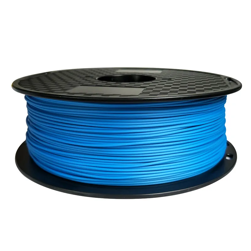 For PLA and other materials, bonding can be done using the appropriate adhesive (selection of adhesive will depend on the plastic) . For ABS plastic, multi-piece assemblies can be glued with acetone. The mating surfaces should be lightly moistened with acetone and held firmly together or, if possible, clamped until most of the acetone has evaporated. At this point, the two parts of your model will stick together. nine0003
Helpful Hint: increasing the contact area with acetone will increase the strength of the joint. This can be done by including block connections in the design.
Pros
- Acetone will not discolor the surface of the part like other adhesives
- After drying, the seam will exhibit ABS properties, making further processing easier and more uniform
Cons
- The joint formed by this cold welding is not as strong as a solid impression
- Excessive use of acetone can lead to aggressive dissolution of the part and adversely affect the final result and tolerances
-
Filling irregularities in ABS plastics
The gray ABS model had voids after sanding. The surface became smooth. nine0003
Tools and materials you will need:
- Epoxy (for small voids only)
- Automotive Putty (large voids and joints)
- ABS plastic and acetone (for small voids only and for ABS parts only)
Process: After sanding or removing soluble backings, gaps often appear in the print. During printing, gaps are sometimes formed, and often this pattern is unavoidable. Small gaps and voids can be easily filled with epoxy and no further treatment is required. Large gaps, or gouges, left from attaching model assembly parts can be successfully filled with automotive putty, which will require additional sanding after drying. nine0057 The putty gives excellent results and can be easily sanded and painted after it has fully cured. The connection will be strong, and will not weaken the plastic. Conversely, autofiller parts tend to be stronger than native plastic.
Gaps in an ABS print can also be filled by making a slurry of ABS filament and acetone ( ABS juice or ABS juice ) that chemically reacts with the part and penetrates any surface voids. A ratio of 1 to 2 between ABS and acetone is recommended. This method will not significantly affect the cleanliness of the surface around the gap if properly applied. nine0003
Help Tip : If gaps are visible on FDM parts before sanding, fill them with epoxy and then sand once until dry. This will greatly reduce the overall time required to achieve a smooth surface.
Pros
- Epoxies are easy to sand and prime, making the surface easy to paint
- ABS juice will be the same color as your part, as long as you use the same filament by color and manufacturer. Therefore, there will be no discoloration of the surface
Cons
- Auto putty or other polyester epoxy will dry opaque resulting in discolored spots on the print
- Requires additional sanding to achieve uniform coverage
- Can affect overall print accuracy if sanding is too aggressive and too much material is removed
ABS and PLA polishing
nine0420 ABS plastics catalog
Catalog of PLA plastics
Tools and supplies you will need
- Polish
- Sandpaper
- Nonwoven wipe
- Toothbrush
- Microfibre cloth or polishing pad
Process: Plastic polish can be applied after sanding to give standard filaments such as ABS and PLA a glossy finish. After the part has been sanded to 1000 grit, wipe off any excess dust from the Non-woven » cloth, then clean it in a bath of warm water with a toothbrush.
Allow the piece to dry completely and buff it with a buffing pad, or by hand with a microfiber cloth and a jewelry polish designed specifically for plastic and synthetics that provides a long lasting shine.
Other plastic polishes, such as car headlight polishes, work on the same principle, but some may contain chemicals that can damage the original material. nine0003
Helpful Hint: For polishing small parts, attach the polishing pad to the Variable Speed Drill (or other rotating tool such as a drill) . Bench grinders equipped with a polishing wheel can be used for larger, stronger prints, but don't polish too long in the same place. This can cause the plastic to melt due to friction.
Pros
- Polishing is applied without the use of any solvents that can deform the part and change the precision tolerances.

- When properly ground and polished, the part will give the impression of a mirror finish, imitating plastic injection molding
- Plastic polish and cleaner are very economical, making this method quite profitable for a quality finish
Cons
- The part must be carefully sanded before polishing if a mirror finish is required. This may affect tolerances
- Primer/paint may not adhere to surface after polishing and you will need additional products
Priming and painting 3D printed products
White PLA part spray painted gray
Tools and materials you will need:
- Nonwoven wipe
- Toothbrush
- Sandpaper
- Aerosol Acrylic Primer
- Polishing agents
- Masking tape (only if using multiple colors)
- Gloves and petal mask
Process: after the part has been sanded properly (up to 500 grit sandpaper is required at this stage) , the print can be primed. The primer should be applied in two coats using an aerosol can.
An aerosol primer designed for painting models will provide an even coverage and be thin enough not to darken the part before painting.
A thick primer, such as one available at the hardware store, may stick together and require more sanding.
Apply the first coat in short, quick strokes at a distance of about 15 - 20 cm from the part to avoid the formation of a thick layer of primer. Let the primer dry and sand down any imperfections with 9 grit sandpaper.0055 500. Apply the final coat of primer with light, quick strokes.
Once the primer is complete, painting can begin. Painting can be done with acrylic paints and artist's brushes, but using an airbrush or spray can give a smoother surface.
Hardware store spray paint tends to be thicker and harder to control, so it's best to use paints made specifically for painting models. nine0057 The primed surface should be sanded and polished (sanding and polishing sticks used in nail salons are ideal for this application) and then cleaned with a non-woven cloth.
Paint over the model using very light layers; the first few layers will look translucent. Once the paint has formed an opaque coat of (usually after 2-4 coats) , allow the model to dry for 30 minutes to allow the paint to set. Carefully polish the paint layer with nail sticks. nine0003
Multi-colour models can be painted with masking tape. Once all layers of paint are ready, remove the tape and buff the paint using polish paper. Polishing paper such as 3M or Zona can be purchased in a variety of grit sizes. You can buy it in a pack in many online stores. It will give the paint a shine that cannot be achieved in any other way.
Helpful Hint: Do not shake the can when using spray paint! The goal is to mix the pigment or primer, shaking the propellants will cause bubbles to form in the aerosol. Instead, rotate the jar for 2-3 minutes. The stirring ball should roll, not rattle. nine0003
Pros
- Professional results with attention to detail
- Excellent appearance of the final product, regardless of the material/color in which the object was originally printed
Cons
- Paint and primer will increase the volume of the model, which will change the tolerances and can cause problems if the part is part of the assembly
- Buying a high quality spray paint or airbrush is not cheap
Acetone baths for ABS products
Smoothed black model of a petal with a spherical surface made of ABS plastic after an acetone bath.
Tools and materials you will need:
- Non-woven cloth
- Sealed container
- Thinner
- Paper towels nine0029 Aluminum foil (or other solvent resistant material)
- Face mask and chemical resistant gloves
Process: line the chosen container with paper towels along the bottom and, if possible, up the sides. It is very important that the steam does not disturb the chamber itself. The chamber may be sealed.
It is recommended to use glass and metal containers.
Pour in enough solvent to dampen but not drown the paper towels. This will also help them stick to the side walls of the container. nine0057 Acetone is well known for its ability to smooth out ABS parts. For PLA, smoothing is possible with various solvents, they work well, but as a rule, with PLA, it is more difficult to get a smooth surface, unlike ABS.
IMPORTANT! When working with any solvent, please follow the safety regulations for the chemical and always follow the appropriate safety precautions !
A small "raft" of aluminum foil or other solvent-resistant material should be placed in the middle of a lined paper towel container. nine0057 Next, place your part on this raft (either side chosen as the bottom on the raft) and close the lid of the container.
Steam polishing can vary in duration, so check the print periodically. Heat can be used to increase polishing speed, but care must be taken to prevent the buildup of potentially explosive fumes.
When removing the part from the chamber, try not to touch it at all, leaving it on the raft and removing it from the container. Any points of contact with the part will generate surface defects because the outer shell will be half dissolved. Allow parts to dry completely before use. nine0003
NOTE . Many aerosol and/or spray solvents are flammable/explosive and solvent vapors can be harmful to human health. Be especially careful when heating solvents and always work in a well ventilated area.
Pros
- Smoothes out many small spots and reduces layer lines present in the print without any additional work nine0029 Creates a very smooth "shell" around part
- A very fast method that can be implemented using improvised means
Cons
- Doesn't "heal" gaps or completely mask layer height
- The dithering process "dissolves" the outer shell of the print, and therefore this greatly affects tolerances
- Negatively affects print strength due to changes in material properties nine0138
- Solvent safe container
- Thinner
- Hook or small screw
- Wire
- Drying rod or rack
- Face mask and chemical resistant gloves
- Print surface smoothes much faster than steam polishing
- Produces much less fumes than other solvent polishing methods and is safer
- Very aggressively smoothes the surface of the part, so the tolerances deviate greatly from the specified
- Immersion too long can lead to complete deformation of the part and a significant change in material properties
- Two-component epoxy (e.g. XTC-3D)
- Foam applicator
- Brushes
- Mixing container
- Sandpaper 1000 grit or higher
- A very thin coat of epoxy will not significantly affect part tolerances (unless the part has been sanded first)
- Resin provides an outer protective sheath around the part
- The layer lines will still be visible, they are under the "smooth" shell
- Applying too much epoxy can cause surface dripping and over-smoothing of print details
- Plating solution. It can be prepared by mixing a metal salt with acid and water, but if the proportions are not accurate, it will be difficult to get a professional result.
 Buying a ready-made solution guarantees that there are no problems with plating. nine0030
 - Sacrificial anode. The anode material must match the metal of the plating solution, so if copper sulfate is used in the solution, then a copper anode should be used. You can use any item made of metal plating (copper wire, for example), or you can purchase a thin strip of metal plating that is made specifically for electroplating.
- Conductive paint or acetone and graphite. The print surface must be conductive for coating, which can be achieved with conductive paint or a 1:1 solution of graphite and acetone. Conductive ink will work on any printed material, but a solution of acetone and graphite will only work on ABS. nine0030
- Power Rectifier - A battery can be used instead of a rectifier, but a battery is not as efficient and will not deliver results as quickly and consistently as a rectifier. A rectifier is also a safer option. It can simply be turned off to stop the current flow during electroplating.
- Conductive screw or eyelet
- Non-conductive vessel
- Lead set
- Non-conductive gloves and goggles. nine0030
- The metal shell increases the strength of the plastic part, which greatly expands the possibilities of its application and use
- The outer metal coating is very thin, so if properly applied, tolerances of 9 can be held tightly0030
- Creates a beautiful surface that, if done correctly, will not look like a 3D printed object
- Typically very expensive to do this at a professional level, and home plating requires a fair amount of professional processing equipment
- Electroplating at home can cause electric shock if not followed
- Email: Sales@3dtool.
Learn more
Chemical solvent baths
Tools and supplies you will need:
Process: Make sure the container you are using is wide enough and deep enough to hold the part and solvent. Fill the container with the appropriate amount of solvent, taking care to minimize splashing. As with steam smoothing, acetone should be used to dip the ABS. nine0057 PLA is sufficiently resistant to solvents, so it may take several passes to achieve the desired result.
Prepare the part for dipping by screwing an eye hook or small screw into an inconspicuous surface of the imprint. Pass the wire through the eye of the hook or around the screw so you can lower your piece into the wire bath. If the wire is too thin, you won't be able to submerge the part in the solvent.
Once the part is prepared, quickly immerse the entire object in the solvent for no more than a few seconds using wire. Pull out the print and attach it to a wire over a dryer rod or rack to allow the solvent to completely evaporate from the surface. The part should be gently shaken after you remove it to facilitate drying and avoid solvent build-up in depressions on the surface. nine0003
Helpful Hint: If the part has an opaque whitish color after drying, it can be hung over a solvent bath for a while so that the evaporating vapors slightly dissolve the surface. This will restore the color of the print and provide a glossy outer layer.
Pros
Cons
Using epoxy to finish prints
The part is sanded and coated with epoxy resin.
Tools and supplies you will need:
Process : After the print has been sanded (sanding first will give better end results) , completely clean it with a non-woven cloth. nine0057 Mix the correct ratio of resin and hardener as directed in the resin instructions. Make no mistake about the proportions. Epoxies are exothermic when mixed, so glass containers and containers composed of low melting point materials should be avoided.
Containers specifically designed for mixing epoxy resins are recommended. The wrong ratio will lengthen the drying time and the epoxy may never be able to fully cure, resulting in a disastrous and sticky part. nine0003
Mix resin and hardener thoroughly according to instructions. Stir gently to minimize air bubbles. The faster the epoxy dries, the better. Most epoxies have a working dry time of only 10-15 minutes, so do your post-processing in the proper order.
Apply the first coat of epoxy using a foam applicator and try to minimize resin buildup on recessed surfaces or other details of the print. Once your part is sufficiently covered with resin, allow it to fully cure according to the manufacturer's instructions. One coat may be enough to smooth the detail, but for optimum appearance, the print should be lightly sanded with fine sandpaper (1 000 grit or higher) . Remove dust with a non-woven cloth and apply a second coat of epoxy in the same manner.
Pros
Cons
Tools and supplies you will need:
Electrophoresis solutions are acids and can cause eye damage if splashed, so appropriate goggles are required. Also, these solutions can irritate the skin and conduct a charge when used. Therefore, non-conductive gloves should always be used.
Finishing process: metal plating can be electroplated at home or in a professional workshop. Proper plating requires a deep knowledge of materials, and what you can do at home has certain limitations compared to what can be done in a professional workshop. nine0057 For a better finish and a wider range of plating options, including chrome plating, a workshop would be the best option. For clarity, the copper plating process will be described below.
At home, galvanization can be done using copper or nickel plate. It is imperative that the surface of the print to be processed is as smooth as possible before coating; any unevenness and visible lines of the layers will start to stand out after coating.
Prepare a cleaned and sanded print. By coating the plastic with a thin layer of high quality conductive paint or a solution of acetone and graphite (if made of ABS) . Allow the conductive coating to dry completely and sand if necessary to ensure a smooth finish. It is extremely important to minimize contact with the print or wear gloves as the sebum on your fingers will interfere with the coating process.
Insert a screw or hook with an eye into an inconspicuous surface of the part, similar to dipping in solvent.
Attach to one of the rectifier leads. This will serve as the cathode. The connection must be made to the negative terminal of the rectifier. Connect the copper anode to the positive terminal of the rectifier using the second power wire and fill the container with enough electroplating solution so that the imprint and the copper anode are completely hidden. Turn on the power rectifier. After the rectifier is turned on, make sure that the part does not touch the anode in any way. nine0003
IMPORTANT! Be very careful at this stage. After the part is lowered into the bath and the system is energized, any contact with the solution, anode or cathode may result in personal injury !
Set the power supply rectifier to 1-3 volts. After that, the metallization process will begin until the part is completely covered with metal. Voltage may be increased to reduce coating time, but should not exceed 5 volts. Simply turn off the straightener and remove the print after a satisfactory finish has been applied. Dry the print with microfiber towels. Coat the part with a special varnish for metal after drying. This will protect it from corrosion.
Pros
Cons
Well, that's all we have! We hope this article was useful for you!
Order 3D printer or FDM consumables , you can