Dimension 3d printer troubleshooting
Slic3r Manual – Dimension Errors
If you're not satisfied by the dimensional accuracy of your prints, first off make sure your firmware is correctly configured: the steps/mm values for X, Y, and Z axes must be calculated according to your belts, pulleys and leadscrews. Please don't calibrate by trial-and-error: those values should be exact. Use Josef Prusa's Calculator.
Vertical dimensions
If your vertical dimensions are wrong (i.e. along the Z axis) -and your object is usually shorter than expected- it means your nozzle is too low, thus the first layer is pressed too much on the print bed. To fix this, you might want to raise your Z endstop or increase the Z offset option in Slic3r.
Horizontal dimensions
The usual issue is about holes being too small. This usually only affects holes on the horizontal plane (XY). There are several reasons for this. Let's see them one by one:
Plastic shrinkage
Plastic shrinks when cooling. Different kinds of plastic exhibit different shrinkage, which might also depend on temperature. Because of such shrinkage, circular (or polygonal) holes laid by the extruder at the nominal diameter will end up smaller after cooling.
More material is deposited in the inside
When you extrude along a curve, more material per distance unit is deposited in the concave side. Such excessive material makes the internal radius shorter. A compensation algorithm was proposed by Adrian Bowyer, and it was implemented in Slic3r some time ago but many users complained about holes being too large – it was removed thereafter since smaller holes are better than larger holes since they can be drilled.
Curves are approximated by polygons
STL files only contain meshes composed by flat triangles, so its planar sections can only contain polygonal shapes. For example, a circular hole is approximated by a polygon:
image
Increasing the number of segments in your CAD before exporting the STL file will help reducing the error.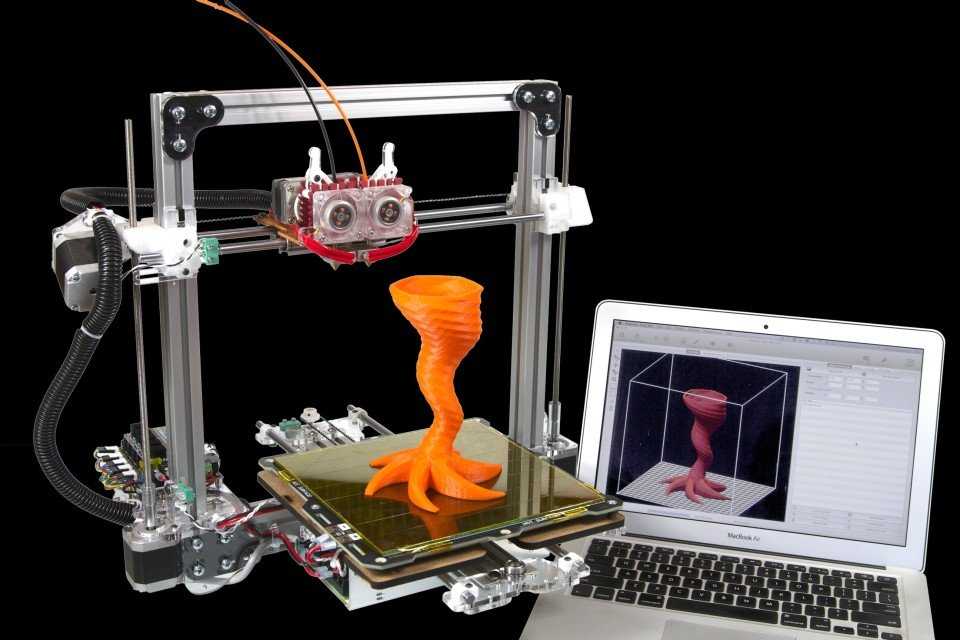 OpenSCAD users might want to use the
 polyhole() function developed by nophead that calculates the optimal number of segments.
Filament tends to cut corners
Since curves are approximated by polygons, there are sharp vertices at their vertices. However, plastic tends to make rounded corners, thus reducing the internal area of the hole even more.
Z wobble
Even if the dimensional accuracy of a single layer was correct, several stacked layers might make the hole smaller if they're not exactly aligned. Z wobble caused by mechanical issues will reduce hole size to the internal envelope of the stacked layers:
image
Non-regular filament section
Low-quality and medium-quality filaments are not very regular in diameter. If you measure their diameter along a single meter of them, you'll often find many different values (and many low-quality filaments are even not perfectly round in section). This continuous variation in diameter will produce irregular flow and the resulting hole will still be the internal envelope of all the layers:
image
Backlash
Backlash is a mechanical defect of one or more axes that basically reduces the amount of actual motion whenever a motor inverts its spinning direction. It's generally caused by loose belts. On printers with a moving bed, its axis (usually Y) is more subject to backlash because of inertia. So, if you get different dimension errors in X and Y, that's caused by backlash. You'll need to tighten your belt. No software hack can reasonably compensate for a badly assembled printer.
Flow math
Okay, all of the above causes do not depend on Slic3r and, when possible, they need to be fixed before attempting any software solution.
That said, the flow math used in Slic3r plays a good role in making correct dimensions, since it tries to guess what the shape of the extruded material will be and how thick the extrusion will result on the horizontal plane given an amount of material. Being an approximation, it carries an error. The usual way to deal with these issues involves tuning the Extrusion Multiplier setting in order to increase/reduce the amount of plastic, thus making extrusions more or less thick. But this will also affect solid surfaces, so it's not the ideal solution.
For more exact dimensions you need to check the External Perimeters First option. Printing external perimeters first will prevent the shift caused by extrudate overlap. On the other hand, printing internal perimeters first hides seams better, so it's your take.
A new XY Size Compensation option was also introduced that allows to grow/shrink object shape in order to compensate for the measured error. Supposing your holes are smaller by 0.1mm, you can just enter -0.05 in this option to get them compensated (negative sign means shrink inwards).
🔥 The definitive guide to solving 3D printing problems by Bitfab
🤬Having problems with your 3D printer? You’ve come to the right place.
In Bitfab we have prepared the definitive guide to solve all your 3D printing problems. Thousands of hours of professional 3D printing behind our back to help you with the setbacks you have with your printer.
And we not only give you the keys to diagnose your printing errors but also the best tips to prevent them from reappearing, fix your printer and calibrate. Pictures, videos and our best tips in a mega article.
👇 Enjoy the guide and use the index if you want to go to directly to the part that interests you.
📖 What do you want to read?
🤬 The most common defects and problems in 3D printing
We have put together a collection of the most common problems that arise when using our 3D printer. They are the same problems that we commonly encounter in our online 3D printing service, and so we have quite a bit of experience dealing with and solving them.
A well calibrated printer, correct lamination and an experienced operator are key to avoiding these problems. By having that you will be able to solve any printing problem.
If you experience any of these issues, follow the instructions we give you and if you still can’t solve them, you have the comment box at the end of the article to tell us your doubts.
❌ Warping, the first layer peels off and the parts bend
Warping is a decreasingly common problem, as the vast majority of modern printers have hot beds. In any case, warping can be caused by the following factors:
- Lack of adhesion to the bed: this can occur due to incorrect height of the nozzle in relation to the base, or poor leveling; but also lack of adhesion to the printing surface.
- Thermal contraction of the upper layers, which when “shrinking” pull on the lower layers. If this occurs, the print surface may even break if it is a BuildTak type, as the sticker will be torn off the bed. This can also happen with glass. This happens mostly with materials such as ABS or Nylon, and it is very difficult for it to happen when printing PLA.
Depending on our problem we can look for a solution accordingly:
For the lack of adhesion there are several solutions. If we are using a glass base, it is highly recommended to use some adhesive to increase the fixation of the part. Some known adhesives are the famous Nelly hairspray, or its more professional version 3Dlac. If we are using ABS we can apply a layer of the mixture known as ABS slurry which we can make ourselves by dissolving ABS in a container with acetone.
If your problem is related to thermal contraction, increasing the adhesion will not help you too much since, as we have said, the ABS when deformed can even break our printing base. To solve this problem we can simply cover the printer with whatever we have at home. A large box can work, as well as a more professional enclosure made in a closet.
The idea in this case is to enclose the heat generated by the bed, so that there is not much difference between the temperature of the first layers and the temperature of the upper layers, which are farther away from the heat of the bed.
Here’s an article that we made explaining this problem more in depth: How to avoid warping and cracking in my 3D prints.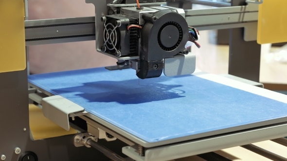
❌ Cracking or delamination
Following on from the above problem is cracking or delamination. We talk about cracking when the layers of a part are not well joined, resulting in these layers being separated (hence the name delamination). This problem can be caused by two different reasons:
- Poor adhesion between the layers: the layers do not stick properly to each other.
- Thermal shrinkage: the layers stick together well, but a difference in temperature between different sections of the part causes it to deform, which can cause some layers to separate.
If the problem is lack of adhesion, it is usually due to low of temperature. Most filaments have a temperature range in which they can be printed.
Within this range, lower values will give us a better aesthetic appearance, since the deposition will be “cleaner”. Conversely, higher values will give us better layer adhesion. Printing materials such as ABS at less than the proper temperature often leads to cracking when trying to bond two layers without applying enough heat.
To check if our part is cracking due to lack of adhesion between the layers, we can try to raise the temperature and/or reduce the speed of the layer fan, as excessive cooling can also affect it negatively. Some materials, like ABS, will always be prone to cracking and will be more difficult to control; others like PLA are very easy to print without cracking.
On the other hand, if our problem is thermal contraction the solution is more complicated, as we must manage to create a warmer environment in our printing area. The optimal solution would be to cover our printer, as indicated in the previous point. This can result in some problems, since an excessive temperature can lead to failures in the electronics: missing steps or losing printing artifacts… it can also cause clogging, since there is not enough difference in temperature between the cold zone and the hot zone of the hotend.
In general, avoiding draughts (and the consequent temperature variations) and covering our printer will help, but we must be careful to avoid the problems mentioned.
❌ Layer shift
Layer shifting is a problem that occurs in the form of a displacement on some axis at a certain height. It can occur in the X-axis, the Y-axis or even both simultaneously. The most common causes of layer shifting are:
- Excessive temperature in the motors, or drivers: the electronics in general are not designed to operate continuously at a very high temperature.
- Lack of power in the motors, usually caused by a very low voltage value in the drivers.
- Mechanical failure: it can happen that we have some of our belt’s teeth broken, or there is some debris on the shafts that can cause a jam in the movement of our printer. Sometimes a wrongly tightened component can also cause layer displacement defects when the whole shaft moves freely.
A general advice would be to put heatsinks, and if possible ventilation, to the drivers of our board. These components basically take care of sending all the necessary air flow to the motors, so they tend to heat up. Likewise, if our printer operates in very hot environments it would be appropriate to add some heatsink to the X and Y axis motors as well. If the drivers are very hot, you will usually hear a knock, knock, knock on the motors when the drivers are briefly disconnected to give them time to cool down.
Additionally, you can check if your printer has drivers with adjustable voltage, and if so, you can increase this voltage slightly by carefully turning the potentiometer on each driver. Be careful when doing this, and always do it with the printer turned off or using a ceramic screwdriver to avoid short-circuiting with a metal screwdriver. If you turn up the power on the motors too much you risk falling into the overheating problem again.
Finally, check that the shafts of your printer are clean and free from obstructions. Also check that the belts and bearings are not too tight (if the bearings are tightened with flanges or screws). Shafts that do not move well, over-tightened belts… cause motors to work harder and may lose steps.
❌ Z-wobble
This problem can be difficult to identify, as it is often not easy to distinguish it from a simple inconsistency in the extrusion. To identify it we must look at whether this inconsistency is repeated on a regular basis. If it seems random, or just noise in general, your problem is probably not z-wobble but an extrusion problem. Conversely, if there seems to be a pattern that repeats periodically such as waves on the surface, you may well have a problem with your Z-axis.
This problem is mostly due to structural failures in the construction of the machine, and is difficult to solve without making major modifications to our machine chassis. First of all check that all the parts are properly assembled, maintaining the perpendicularity and making sure that there are no loose screws.
Try to tighten all the screws on the couplers that connect the z-axis motors to the spindles. Also check that there is no wobble between the spindle and the trapezoid nut. It is complicated to give a correct solution, because the axis needs some freedom to move to compensate small errors in the chassis, such as corners that are not perfectly perpendicular.
A good solution that is not too expensive is to replace the motor-coupler-spindle assembly with a motor with a built-in spindle. We can also add reinforcements to our printer so that the frame of the printer does not wobble at the top.
❌ Stringing
Stringing is one of the most common problems in novice parts in the world of 3D printing, so if your parts have a lot of strings don’t worry, it’s totally normal and quite easy to solve.
Stringing appears when, as the hotend moves between two sections of our print, a small amount of plastic drips off and sticks to both sections, leaving a small thread in between.
This problem can be caused by the use of a bad quality hotend, but usually the machines have a hotendsn of sufficient quality, so the problem almost always comes from bad lamination in the slicer.
The most important parameters you should check in your slicer to minimize the stringing are the following:
- Temperature
- Retraction distance
- Retraction speed
Temperature is a vital factor and probably one of the 5 most important settings in your profile. If you have a lot of stringing you are almost certainly melting at too high a temperature. Remember that all materials have a range of temperatures in which they can be printed, so try lowering the temperature and bringing it closer to the lower limit recommended by the manufacturer. If you are already using a very low temperature and still have stringing, check the following points.
While it is not possible to “suck” plastic out of the nozzle, as no negative pressure can be created, it is possible to minimize the pressure on the nozzle by pulling the filament out of the hot zone of our hotend. The shrinkage distance is very dependent on our printer, as both the melter and extruder and the type of extrusion (direct or bowden) must be considered. Most bowden printers perform well with a shrinkage value between 3mm and 6mm, and direct extrusion printers between 0.5mm and 2mm.
The speed of retraction is another important factor, as the higher the speed the lower the stringing. This speed will depend on the motor of our extruder and also on the type of extrusion (1:1 vs 3:1 like the Titan extruder). Generally values between 40 mm/s and 60 mm/s usually work, but if you have any doubt, please ask in a forum or group dedicated to your specific printer.
Additionally, almost all slicers or laminators have different more advanced settings that can help reduce the stringing, but these will only be of importance if the three previous ones are well adjusted. This is a very broad topic and we could make an exclusive guide about this problem, so if you want to see it, leave us a comment!
❌ Overheating, curling
One of the easiest problems to diagnose is overheating.
As we can see in the image, melting our plastic at an excessive temperature will cause the parts to look deformed, with the center of the layer sunken. This is because when melted at too high a temperature, the material does not have time to cool down, and that is why the layers can collapse or sag.
These deformations will be much more pronounced in small areas, such as small peaks of our part, where instead of a clean figure, a deformed churro will remain.
The solution to this problem is simple: lower the temperature. We must also play with the values of the layer fan, since a high temperature can favor a more fluid extrusion and we can compensate this temperature with a good cooling. In this way the material will be cooled down quickly and we will be able to obtain optimal results.
❌ Elephant’s foot
The elephant foot is a defect consisting of the expansion in the horizontal plane of the first layers of our part. It can occur due to two things or, normally, a combination of both: the nozzle is too close to the bed or the temperature of the bed is too high.
If the nozzle is too close to the bed, it is obvious that the first layers will be more flattened and therefore expand in the XY plane. To solve this problem we must correctly level our first layer, as indicated in a previous section of this article.
An excessive bed temperature (say, 90 or 100 degrees for PLA) can cause the newly deposited plastic to expand and deform, causing this very characteristic effect.
❌ Ghosting, ringing
The best article on this topic on the internet is the 3D Campy post by 3DSpana about ghosting, because he dedicated himself to try different combinations and components, taking pictures of the results, so you can see how decreasing the weight of the axes affects ghosting. If you prefer it on video, here’s the summary:
😍 Keys to print correctly with your printer
You’ve seen the list of problems we’ve collected. Now you have to know how to DO things.
Knowing your printer and laminator is the key to error and defect-free printing, so here are some tips to avoid problems and help you diagnose and fix them:
✅ Printing speeds
One of the most common mistakes we find on beginners is wanting to print too quickly on their first parts.
The printing speed is one of the most important printing parameters to obtain the best printing quality and an excess of speed affects the part very negatively for many reasons: vibration, extrusion problems, overheating, loss of steps…
One of the first things you have to do when you encounter a problem is to reduce the printing speed to see if it is solved. We usually print almost all parts between 40 and 60mm/s, no more is needed for most cases. In a printing service the most important thing is reliability and when you are looking for reliability it is best to print at reasonable speeds so you don’t have to throw the parts away.
It is not necessary to print your parts at 100mm/s, especially the first ones. Yes, we all know someone who does it and gets it done, but it’s not the best way to make sure they come out right.
✅ Bed adjustment and leveling
Learning to set the bed correctly level and the extruder at the right height is one of the first steps we take with a new 3D printer.
Here’s what a properly adjusted bed looks like: the height of the first layer has to be correct across the entire surface of the bed.
First layer too close
If your first layer is too close to the printing surface, you can cause jams, scratches on the bed, parts with the wrong dimensions, elephant foot…
Correct first layer
When the first layer is correct, the threads deposited by the extruder touch each other and are not too flat against the bed.
First layer too separate
A very separate first layer can be noticed by the separate threads.
Parts printed in this way are usually detached from the bed or warp.
And how do you properly level a hot bed? Our preferred technique is paper in the corners. It is not necessary to have a printer with self-leveling, the best thing is to have a reliable and well calibrated printer to print with quality.
✅ How to prevent and fix extruder clogging
Extrusion jams are the number one cause of failure on a farm like ours. You may have mastered your printer but the jams are always going to be there, so it’s critical to understand them and be able to prevent and fix them.
If you don’t yet understand how a 3D printer extrusion works and what the common terms for referring to them are, you can first check out our guide to 3D extruders.
Causes for clogging
Clogs arise from many different causes, sometimes in conjunction with each other. I believe the best way to solve them is to first understand all those causes and then try a series of techniques that can help fix them.
- Contamination at the tip and print canal. Impurities that are deposited in the print canal or at the tip of the nozzle and hinder or completely block the flow of the filament.
- PTFE/teflon degraded. Teflon hotends in the hot zone require maintenance of the Teflon, which when degraded clogs the filament flow.
- Extruder problems. Maybe your extruder is not working properly:
- Too much tension or too little tension in the dock
- Low voltage in the driver that does not give enough power to the motor
- Dirty thrust wheel, with teeth covered with filament debris
- Any loose or broken parts
- Scratching the filament. This is very, very important to understand. When we see the scratched filament, nibbled by the extruder wheel, it is not always the cause of the clogging. All printing clogs, whatever the cause, end up scratching of the filament. And only those clogs that are due to spring tension and excessive shrinkage are the root cause of the clog itself.
- Tip scratching the base. If the first layer is too low, it can interrupt the flow of the melted plastic and quickly cause a clog in the extrusion system.
- Watch out for shrinkage. A part with a lot of very fast retractions can end up scratching the filament. And long, slow retractions can overheat the cold zone of the extruder and cause clogging as well. In general, retractions won’t cause your clogs, but you should always keep an eye on them.
- Poor cooling. Cooling is a fundamental variable in all-metal hotends. If your extruder is 100% metal like the E3D V6 you have to be very careful with this and with excessive shrinkage.
Unclog the nozzle with acupuncture needles
The technique of passing an acupuncture needle through the printhead is most useful if the real cause of your clog is an impurity. The nozzles themselves last many hundreds or even thousands of hours of use, so you will almost never have to change them.
Most likely a particle has been deposited in the nozzle and you should be able to get it out with the needle. We heat the head and stick the needle while hot, and then pull out the filament with the particles that might be causing the clogging embedded in the molten filament.
Repeat this process until the plastic comes out of the nozzle again easily.
Hot and cold pulling
The pulling takes a little longer to do than using the acupuncture needle, but it cleans the impurities better and also takes away the filth not only from the tip, but from the whole interior of the hotend.
They are easier to explain with a video like the one below:
Teflon switching
In hotends with Teflon liner it is necessary to change this component, in general, every several hundred hours. The Teflon or PTFE liner is a small tube that goes in the hot zone of your hotend to guide the filament in the last centimeters of run, and that is degraded due to the temperature it reaches. Changing it is a job that you will have to learn to do to properly maintain your printer.
Before the tube degrades completely, you will notice that your printer is having more and more trouble printing, the filament thread that comes out is thinner and it’s harder for it to deposit material on the parts that you print faster.
In every printer the change of Teflon is different, but here is the example of the Hephestos 2 from BQ to help you understand it better.
Adjusting the printing parameters
There are clogs that can occur because our laminate is not well adapted to the type of part and printer we are going to use.
To allow your printer to extrude more easily you can try:
- Printing slower
- Printing at a higher temperature
- Printing thinner layers
- Reducing the flow rate if you have more than 100%
These are all tricks that reduce the requirements on the extruder and melter because they require less flow through the hotend and heat the plastic to make it more fluid.
Retractions can also influence extrusion problems:
- Too many or too fast retractions can result in scratching of the filament in the extruder.
- Too long or too slow retractions can cause cooling problems in your melter (especially if it is all-metal) or end up clogging the plastic in the cold zone of the melter.
If you don’t know how to fix it, dissasemble the extruder and hotend
The best way to attack a mechanical problem that you don’t know how to solve is to proceed to disassemble what you want to fix. Taking apart a hotend and an extruder is quite simple and will allow you to see inside what is happening and reflect on the problem.
When you dismantle your extruder you will notice that there are some broken parts, dirt somewhere, some loose screws…
If you disassemble the hotend you will be able to see the state of the Teflon, the tension of the hotend threads and if there is print residue deposited in the filament canal.
In either case, take the opportunity to clean the parts to prevent errors in the future.
👋 That’s it for the 3D printing troubleshooting guide by Bitfab
Thank you so much for getting this far.
If you have any doubt or a different problem just put it in the comments and we will help you solve it, or maybe even add it to the rest of the problems 😁
👋 Greetings and thanks again!
Problems, defects, 3D printing errors and solutions
Often during the operation of a 3D printer, problems may arise due to which defects appear on the finished model. Or instead of a neat product, plastic noodles suddenly appear on the table.
In fact, the causes of defects can be conditionally divided into 2 types - these are physical and software.
Physical ones are those that arise due to problems with the mechanics or any other causes that can be eliminated physically. These include problems with printer mechanisms (belt tension, backlash), clogged or deformed nozzle, incorrect table geometry, etc.
Software - these are defects that occur due to incorrect slicer settings or, less often, errors in the printer firmware. For example, incorrectly selected print speed, retract settings, incorrectly selected temperature for plastic, etc.
Very rarely, the problem may lie in the wrong or “flying” printer firmware (although usually the printer simply will not start then), overheating of some boards during printing, etc. These are rather special cases, so we will not consider them.
Model peels off or does not stick to the platen
This is the most common 3D printing problem. Every 3D printer has had a case when the first layer treacherously rolls, clinging to the extruder, or the most offensive - when it tears off a partially printed model from the table. The first layer must stick tightly otherwise nothing will be printed.
Gap between table and nozzle 9 too large0023
This is the most common reason. You just need to set the correct gap between the table and the nozzle.
Modern printers often use an auto-calibration (auto-leveling) table system or an auxiliary table leveling program. To calibrate such printers, use the instructions. If there is no manual, it can be downloaded from the manufacturer's website.
If you have a simple printer without auto-calibration, a self-assembly or KIT kit, use a probe or a piece of paper folded in half to calibrate. The probe should be slightly pressed against the table by the nozzle. Before calibration, the table and extruder must be heated. Align the table surface over each adjustment screw (there may be 3 or 4) in turn, and only then check the center point.
If you're having trouble getting your table surface perfectly level, try raft printing. Raft is a thick substrate in several layers that is printed under the model. It will help smooth out the slight curvature of the table.
A small cheat sheet to determine the correct gap on the first layer
Plastic with poor adhesion
Some types of plastic, due to various reasons, such as large shrinkage, do not adhere well to the surface of the printing platform. In this case, try using stickers or special 3D adhesives to improve adhesion between the table and the first layer of plastic.
In the early days of 3D printing, there were experiments with different homemade 3D adhesive recipes. ABS diluted in acetone, BF glue, sugar syrup and even beer. Some experiments have been successful. Until now, some enthusiasts use some types of hairspray or glue sticks as 3D glue. But still they are inferior in their properties to industrial 3D adhesives.
Some types of high temperature plastics with a high percentage of shrinkage (ABS, Nylon, etc.) may peel off the table during printing. This is due to uneven cooling and “compression” of the model (the lower layers have already cooled down, but the upper ones have not yet). For such plastics, it is imperative to use a 3D printer with a heated table and a closed case.
Plastic temperature too low
The hotter the plastic is when it exits the nozzle, the better it will adhere to the print bed. It is better to print the first 5-10 layers at a higher temperature (+ 5-10 degrees) and turn off the blower fan.
Wrong first layer settings (speed and thickness)
A thicker layer sticks easier, so the standard first layer is 0.3mm thick. With an increase in print speed, the heating block may simply not have time to heat the plastic to the desired temperature and it will stick to the table worse. Before printing, check the speed and thickness settings of the first layer in the slicer.
A lot depends on how the 3D printer prints the first layer. Try to control the printing of the first layer and only then leave the printer to work alone.
Plastic does not choke from nozzle
The printer has already begun to print, but the print table remains empty. Or part of the model did not print.
Clogged nozzle
In 3D printing, a nozzle is a consumable. The nozzles are clogged or worn out (frequency depends on the type of plastic). The simplest thing is to replace the nozzle. But if there was no spare at hand, you can try to clean the old one. To do this, there is a whole set of thin needles. Or you can heat a clogged nozzle above the melting point of the plastic and “burn out” the blockage. But later it is still better to replace the nozzle.
Low temperature nozzle
You need to increase the temperature of the extruder in the slicer settings or check the thermistor and heating block. Sometimes the thermistor may not read the temperature correctly due to a malfunction or incorrect 3D printer firmware settings.
If the problem occurs after replacing the thermistor - contact the manufacturer or read articles about PID tuning.
Empty extruder
As the extruder heats up, plastic begins to ooze out of the nozzle. Because of this, the extruder may start printing half empty. Because of this, part of the first layer is not printed. You can push the plastic manually by simply pushing the bar into the nozzle. Or solve this problem programmatically - in the slicer, add a contour print around the model (one line).
Some manufacturers and 3D enthusiasts add a line print on the edge of the table at the beginning of each GCode. This is done so that there is plastic in the nozzle by the time the model is printed.
Feed mechanism does not push through plastic
The plastic pushes the feed mechanism to the extruder - a motor with a special pulley put on the shaft. If for some reason the plastic is not pushed through (nozzle clogged, extruder temperature low, etc.), then the pulley “gnaws” through the bar. You need to push the plastic bar with your hands or cut off the damaged piece.
Elephant foot
The first layers of the model are wider and protrude beyond the boundaries of the model. This is due to the fact that the upper layers put pressure on the first ones that have not yet cooled down and flatten them.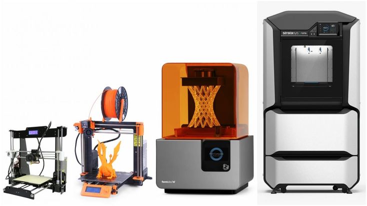
High table temperature
Due to the too high temperature of the table, the lower layers remain soft for a long time. Try lowering the table temperature. It is better to reduce gradually (in increments of 5 degrees). You can try to turn on the blower when printing the first layers.
Small gap between nozzle and platen
If, when printing the first layer, the nozzle is too close to the table, then excess plastic will be forced out. After a few coats, this will not be as noticeable, but can lead to the effect of an “elephant's foot”.
Plastic re-extrusion
When too much material is squeezed out of the nozzle, the walls of the model are not smooth, but bumpy, with sagging.
The solution is software - in the settings of the slicer, you need to set the material feed rate (fluidity) to a lower value. The average value is 95-98%.
It is worth checking the diameter of the rod. If its size is greater than 1.75, then the plastic will be squeezed out more than necessary.
Plastic underextrusion
The plastic is squeezed out too little, because of this, gaps may appear between the layer. The finished model will be fragile and fragile.
Wrong thread diameter
Check the filament diameter in the slicer settings. Sometimes, instead of the popular 1.75, the default is 2.85.
Incorrect feed rate settings
Check the fluidity settings in the slicer. The average should be 95-98%.
Clogged nozzle
Something could get into the nozzle and partially block the exit of the plastic. Visually, the plastic will choke from the nozzle, but in a smaller amount than necessary for printing.
Hairiness or cobwebs on finished model
Thin threads of plastic protrude from the outer wall of the model (most often on one side). The defect appears due to the flow of plastic from the nozzle during idle movement.
Insufficient retract
A retract is a slight pull of a plastic filament from an extruder. Due to the retract when the extruder is idle (from layer to layer or from model to model), heated plastic does not drip from the nozzle. For some flowable plastics (eg PETG) the speed and amount of retraction must be increased.
"Hairiness" can be easily removed by grinding or cutting off the threads with a sharp scalpel.
High temperature extruder
The higher the extruder temperature, the more fluid the plastic becomes. It is important to find a balance so that the plastic is not too liquid and sticks well in layers.
In the selection of the optimal extruder temperature, a test model - a tower - helps a lot. It clearly shows how plastic behaves when printed at different temperatures.
.
Temperature test
Top "perforated" or uneven
The top of the model is bumpy or with holes. The problem may arise if the top of the model is flat. For example, like a cube.
Insufficient airflow
When printing the top plane (cover), the plastic does not have time to cool down and remains too liquid. Because of this, the threads are torn and holes are formed. Increase the fan speed on the last layers.
Few top layers
The top of the print may be too thin and deform as a result. Check slicer settings. The number of upper layers is not recommended to be set less than 6.
Low percentage of filling
If the infill percentage is too low, then the top layer will simply have nothing to rely on. Increase the fill percentage in the slicer settings.
Model deformation
Some parts of the model seem to have melted in some places or on one side. The problem most often occurs when printing with PLA plastic. The defect appears due to the fact that the plastic does not have time to cool and deforms.
Insufficient airflow model
Turn the fans on to maximum. If their power is not enough (in some printers, the fan is located only on one side), you can put a regular desktop fan and direct it to the 3D printer table.
Small model
Small models are difficult to blow well. Try to print small items alongside larger ones, or place several identical models in different corners of the table. So the plastic will have more time to cool.
Layer offset
Layers shift along the x or y axis during printing.
Print head jam
Turn off the printer and try to move the extruder along the x and y axes with your hands. The extruder must move freely. If there are jams, check the mechanics of the printer. Bearing wear or the curvature of the shafts may be to blame.
Electronics overheating
Sometimes electronics problems can be to blame for misaligned layers. The most common cause is overheating of the drivers or too low current exposed to them.
Table top is loose
This is most often seen in 3D printers with glass. During printing, the nozzle may hit the model and move the glass slightly. Before printing, check if the glass or other printing surface is well fixed on the heating table.
Skip layers
Small holes are visible on the print, or the shell of the model is not continuous.
Teflon tube deformed
There are 2 types of thermal barriers - all-metal and with a Teflon tube. If overheated, the Teflon tube may deform. Plastic will pass through it, but in a smaller amount.
Low extruder temperature or high print speed
If the extruder is not heated enough, then the plastic will not be liquid enough and simply will not have time to be forced through the nozzle. The higher the print speed, the higher the extruder temperature should be.
Sometimes the outer walls print well, but the infill is “torn”. In this case, slow down the infill print speed in the slicer.
Model bundle
Cracks form on the surface of the printout during or after printing. Cracks can be large or very small. Most often, this problem occurs with plastics with a high percentage of shrinkage - ABS or Nylon.
Sudden temperature difference (if model delaminates during printing)
With a sharp temperature difference (for example, a draft), part of the model cools down faster. This leads to uneven shrinkage and incorrect distribution of internal stress. For plastics with low shrinkage, this is not critical. But if the shrinkage percentage is more than a few percent, the model may burst in layers.
For printing with such plastics, it is recommended to use a printer with a closed housing. If this is not possible, try to avoid drafts and sudden temperature changes in the room where the 3D printer prints as much as possible.
Print temperature
Due to too low printing temperatures, the layers may not “stick” well to each other. Raise the print temperature in the slicer settings.
Hardening (if the model cracks after printing)
Sometimes cracks appear on the model a few days after printing. This is due to uneven distribution of internal stress after cooling. You can try to “harden” the finished product.
For hardening, the model is placed, for example, in an oven, and heated to the softening temperature of the plastic. After that, the heating is turned off and the oven is left to cool slowly with the model inside. Due to this, the stress inside the print is distributed more evenly. But accuracy is very important in this method - if you make a little mistake with the temperature, the finished product can “float”.
Ringing
In places where the extruder changed direction, ripples are visible. Most often it looks like a shadow around the “sharp” protruding elements of the model.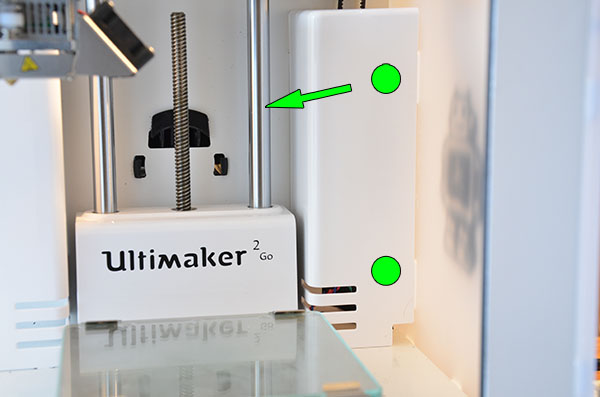
Mechanical problems
Sometimes the problem occurs due to extruder play. Check if the extruder mount to the rails is loose. Be sure to check the tension of all belts.
High print speed or high accelerations
Moving the extruder too fast can cause vibrations that cause ripples on the wall of the model. The lighter the weight of the extruder, the less noticeable the ripples will be. To get rid of ringing, simply reduce the print speed in the slicer settings.
Slits for thin-walled models (not solid shell)
The thin wall of the model is not solid, but consists of two thin walls with a narrow gap between them. This problem is often faced by fans of printing "cutting" for baking.
Left model with wall defect, right without
Wall thickness and nozzle diameter mismatch
If the wall thickness is 1 mm, and the nozzle diameter is 0.4, it turns out that for a solid wall, 2 nozzle passes are few, and 3 are already many.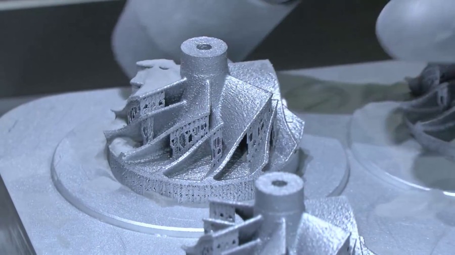 The result will depend on the slicer algorithm, but most often you will get 2 walls with a thin slot in the middle (the slicer cannot change the wall thickness). The solution to the problem may be a slight refinement of the 3D model or the use of a different slicer.
Algorithms for calculating 3D models are constantly being improved and refined, and now this problem is less common.
When modeling, take into account not only the thickness of the nozzle, but also the percentage of “overlapping” of lines on each other. If you have a nozzle with a diameter of 0.4 - make the wall in your model not 0.8, but 0.7 - 0.75.
Wrong model geometry
When instead of a circle you get an oval, and instead of a square you get a semblance of a rhombus.
The main reason is malfunctions in the mechanics of the printer. Be sure to check:
Belts
Check belt tension in x and y. Over time, belts stretch and may need to be tightened or replaced. Each 3D printer has its own way of tightening the belt. If the belts are slightly stretched, you can tighten them with the help of a "spring".
Loose pulleys, etc.
Check if all bolts and nuts are tight. Are there backlashes. Pay special attention to tightening the pulleys located on the motors along the x and y axes.
Sagging of some parts of the model
Some parts are not printed, broken, or instead of a neat surface, a swollen plastic snot is obtained.
No support for overhangs
A 3D printer cannot print in the air, so if there are overhanging elements in the model, you need to set supports - supports. The slicer can set the necessary support itself, you need to check the appropriate box in the settings.
When printing with soluble support, you can set the gap between the model and support - 0. This will make the surface smoother. If the support material and the model are the same, you need to add a small gap. Otherwise, it will be difficult to separate the support from the model.
Split model
Sometimes the supports can take more plastic than the model. In this case, to save material and time, it will be more convenient to cut the model. If you have more than one 3D printer, then the model will print several times faster.
When cutting the model, you can leave grooves or mortgages so that the pieces of the model are connected without displacement.
Totals
In this article, we talked about the most popular 3D printing defects and how to solve them. Don't be intimidated by such a long list. Some problems are rare and you are unlikely to encounter them.
There is a list of problems that arise due to the design features of a 3D printer, so try to choose a printer that suits your needs. To do this, you need to understand what products and what material you need.
Problems associated with printing algorithms are quickly eliminated by software developers.
Do not be afraid of possible difficulties and each seal will be successful.
3D drug printing
September 11, 2018
Popular science competition "Bio/mol/text"-2018
Overview
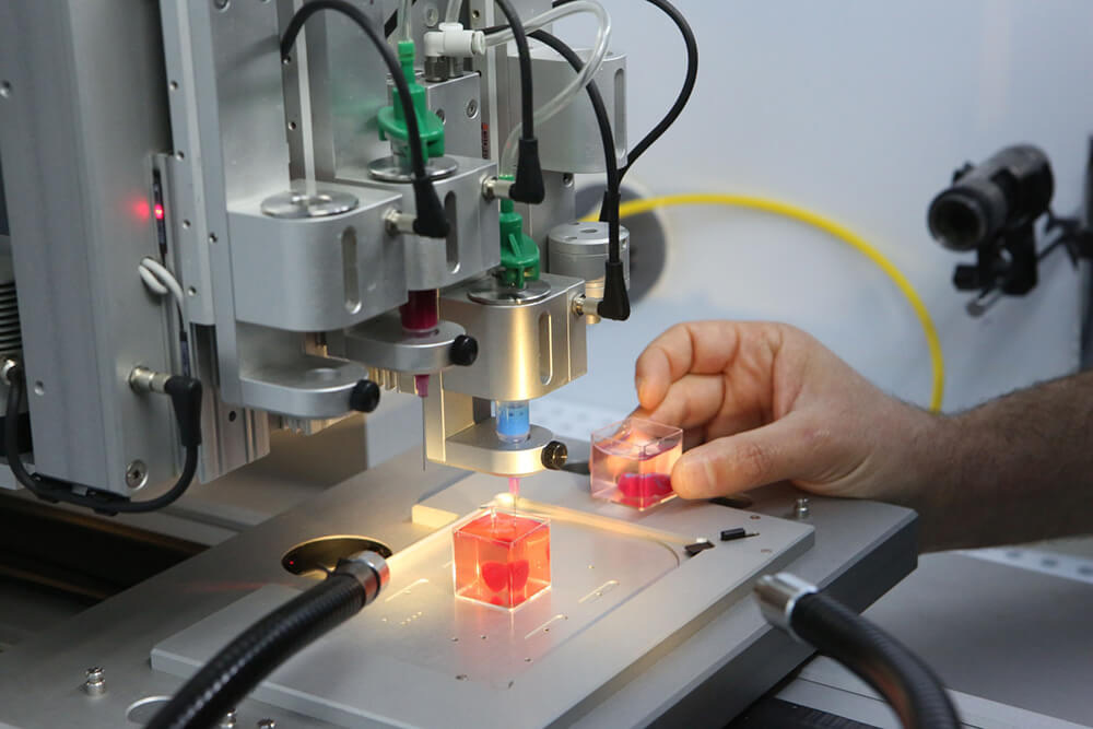
Tablet formed by printing layers of polymer mixed with drug
Alvaro Goyanes
-
Author
- Alexey Korolev
-
Editor
- Andrey Panov
Topics
- "Bio/mol/text"-2018
- Biology
- Biotechnology
- The medicine
- Personalized medicine
- Pharmacology
Article for the bio/mol/text contest: Recently, 3D printing has become one of the most revolutionary and powerful tools in many areas. The pharmaceutical industry is no exception. This article will tell readers about the history of 3D printing in the pharmaceutical industry, the latest developments and achievements in this field, and the prospects for the development of 3D printing in the industry.
This work was published in the nomination "Biopharmaceuticals" of the competition "bio/mol/text"-2018.
The general sponsor of the competition is the Diaem company: the largest supplier of equipment, reagents and consumables for biological research and production.
The partner of the nomination is the medical company Invitro.
The audience award was sponsored by the Genotek Medical Genetics Center.
"Book" sponsor of the competition - "Alpina non-fiction"
Introduction
Now 3D printers can create almost everything. From car parts and fashion accessories to transplant organs and pharmaceuticals. For example, 3D printers can print medical devices with intricate designs, geometries, and features that fit a particular patient's anatomy.
3D bioprinting of organs and tissues is described in the articles " Organs from the laboratory " [1] and " Artificial organs and tissue engineering " [2]. — Ed.
Medical 3D printing is rapidly revolutionizing healthcare. The use of 3D printing in medicine brings wide-ranging benefits: personalization of medical devices, medicines, cost-effectiveness, increased productivity, and democratization of design and production.
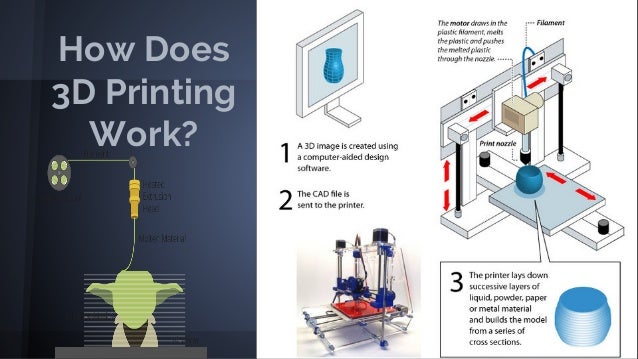
Before we start delving into the topic of 3D printing in the pharmaceutical industry, let's figure out what 3D printing actually is.
Three-dimensional (3D) printing is an additive (additive) manufacturing method in which objects are made in layers by melting and sintering solid or solidifying liquid materials (ceramics, plastics, metals, powders, liquids, or even living cells).
There are about two dozen 3D printing methods that use different printing technologies, resolutions and speeds. There are hundreds of materials from which you can recreate a 3D object of almost any shape.
In order for a three-dimensional object to come into being, you must first create a digital model in a 3D editor, or CAD program, and export it to STL format. Using a special slicer program, translate the STL file into a control G-code for a 3D printer, prepare the 3D printer for work, and start printing. The most important elements of the printer are working platform (on which the formation of the object takes place) and printhead (it forms the object layer by layer). Some time passes (if the object is small - a few minutes or hours, and if it is large, then printing can take more than a day), and voila, the object is ready!
What is 3D printing we learned, move on.
A bit of history
Figure 1. The most important advances in 3D printing in the pharmaceutical industry
- Early 70s. Pierre Ciraud ( Pierre Ciraud ) described the method of applying a powder material and then solidifying each layer under the influence of a high energy beam.
- 1984 Stereolithography (SLA) invented by Chuck Hull ( Chuck Hull ) was the first commercially available 3D printing technology. This method is based on the photopolymerization of a liquid resin with ultraviolet light.
- Mid 1980s. Carl Deckard ( Carl Deckard ) developed a method of solidifying layers of powder using a laser beam, which he called the method Selective Laser Sintering (SLS) .
- 1989 Scott Crump ( Skott Crump ) patented rapid prototyping (FDM) technology is a method that uses a thermoplastic material to form a 3D object. Otherwise this technology is called Fused Deposition Modeling .
- 1990s. Invented the DOS method , which is basically the same as used in inkjet printers.
- 2008 Invented the RepRap printer, a self-copying mechanism for rapid prototyping.
- 2015 The American company Aprecia Pharmaceuticals has developed ZipDose technology, which makes it possible to form tablets that are convenient because they dissolve quickly in a small amount of water. This technology was used to produce the first FDA-approved Spritam® drug printed on a printer ( Food and drug administration , US Food and Drug Administration) [3].
Dictionary
- DOD
- ( Drop On Drop ) liquid layering.
- DOS
- ( Drop On Solid ) hard overlay.
- FDM
- fused deposition method, additive manufacturing technology.
- SLA
- stereolithography, additive manufacturing technology for models from liquid photopolymer resins.
- SLS
- selective laser sintering, additive manufacturing technology.
- STL
- file format widely used for storing 3D object models for use in additive technologies.
How drug printing works
Many different methods of 3D printing have been invented and developed over its 40 year history.
Basic 3D printing methods (fig. 2) are based on:
- solidification of powder material
- curing fluid
- extrusion [3]
Figure 2. 3D printing methods used to create medicines
Despite the variety of 3D printing methods, each of them includes the following steps, which we talked about at the beginning (Fig. 3) [3] :
- designing a 3D object using software and optimizing the geometry of the object according to the printer specification;
- export of a 3D model to a file format recognized by the printer, such as STL;
- importing a file into the software and creating layers in it that will be printed. The height of the printed layer significantly affects the quality of the object, as well as the print time;
- fabrication of an object by subsequent application (or curing) of layers of material.
Figure 3. Stages of 3D printing, development
Application of 3D printing in pharmaceuticals (examples) see where these technologies are already being successfully used to create pharmaceutical products.
Example 1
As reported above, the first 3D printed drug was Spritam® (Fig. 4), developed by the American pharmaceutical company Aprecia Pharmaceuticals and approved by the Food and Drug Administration (FDA) . The active substance of the drug - Levetiracetam is an antiepileptic drug. Levetiracetam is able to quickly dissolve in the mouth, the time of disintegration (dissolution) of the drug is from 2 to 27 seconds (average - 11 seconds). A small sip of water is required to disintegrate the drug. The liquid formula, which binds levetiracetam and excipients for the manufacture of the drug, contains flavor-masking additives that improve the patient's condition [4].
Figure 4: Spritam® (levetiracetam), the first 3D printed drug
Aprecia Pharmaceuticals
Example 2
FabRx is a British biotechnology company specializing in the development of 3D printing technology for pharmaceuticals and medical devices. The company was founded by a group of scientists from University College London who saw the potential of 3D printing technology to create drugs [5].
Figures 5-7 show FabRx designs.
Figure 5. Gummy-like drugs in a variety of shapes, sizes, colors, textures and flavors. FabRx makes them attractive to different patient groups, especially young and old people.
fabrx.co.uk
Figure 6. FabRx researchers experimented with the sizes and shapes of preparations and conducted a study that showed that a pyramidal tablet dissolves faster in water than a cylindrical tablet
fabrx.co.uk
Figure 7. University College London scientists also experimented with different drug forms (octopus, dinosaur, cat, monkey, and others) on a pediatric patient population
The future of 3D printing drugs in pharmacies is closer than you think
There are few examples, as 3D printing is just being introduced into the pharmaceutical industry, and today only a few companies are engaged in 3D printing of drugs.
Advantages and prospects of 3D printing in pharmaceuticals
Advantages
- Customization and personalization.
3D printing technologies allow dosage forms, release profiles and dosage to be customized for each patient. For example, for small patients, a tablet can be printed in the form of some cute animal of any color (Fig. 7).
- Improving cost efficiency. 3D printing will reduce production costs by reducing the use of unnecessary resources. Some drugs can be printed in forms that can be easily and conveniently delivered to the patient (Fig. 8).
- Democratization. Another feature of 3D printing is the democratization of product design and manufacturing. As the cost efficiency of 3D printing increases, the products become orders of magnitude cheaper. [6]
Figure 8. FabRx products
fabrx.co.uk
Perspectives
In the distant future, perhaps if 3D printing develops, everyone will be able to print a drug at home. So far, this can only be a dream. But in the near future, as the researchers suggest, drugs can be printed in pharmacies and hospitals.
Can 3D drug printing replace traditional drug manufacturing technologies? No - it will require huge investments, trained employees and a number of other things. Yes, and large pharmaceutical companies can prevent the penetration of 3D printing into pharmacies and hospitals. 3D printing is unlikely to catch on in large enterprises, as 3D printers print much more slowly than pharmaceutical production machines. Another significant barrier that may prevent the widespread use of 3D printing in pharmaceuticals is the long and costly obtaining approvals from the quality control services of medicines. In addition, manufacturing regulations and government legal requirements also hinder the spread of 3D drug printing [6].
Pharmaceutical 3D printing is young and still evolving. I think that 3D printing will not be able to capture the pharmaceutical market, since Big Pharma is not going to give up. And as already mentioned, in the world there are only two companies aimed at the development of three-dimensional printing of drugs - this is the American company Aprecia Pharmaceuticals and the British company FabRx.