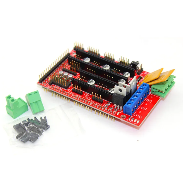
Arduino mega 3d printer shield
Arduino MEGA Shield - RAMPS
Informatie (ENG):
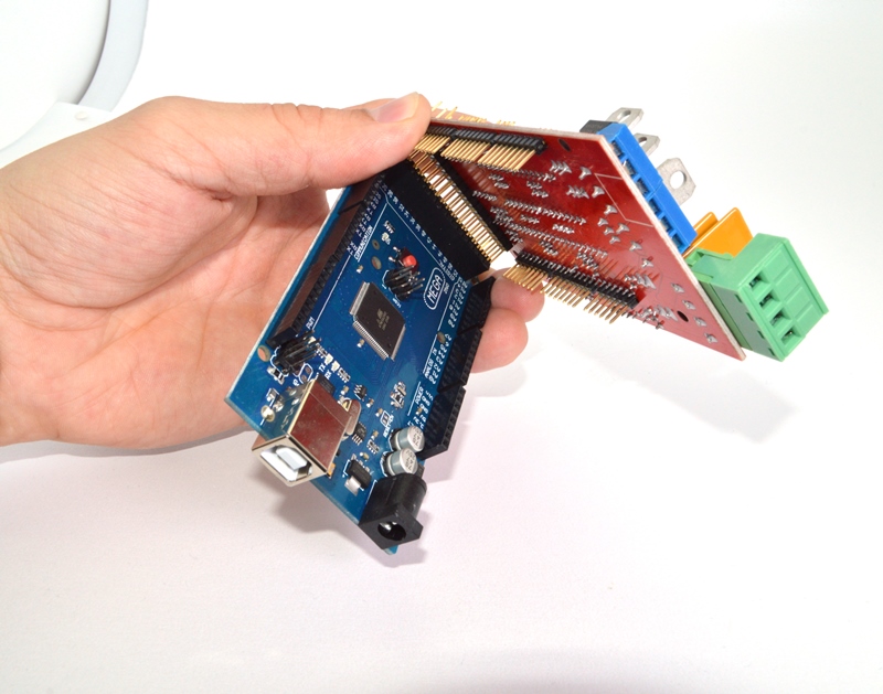
RepRap Arduino Mega Pololu Shield, or RAMPS for short. It is designed to fit the entire electronics needed for a RepRap in one small package for low cost. RAMPS interfaces an Arduino Mega with the powerful Arduino MEGA platform and has plenty room for expansion. The modular design includes plug in stepper drivers and extruder control electronics on an Arduino MEGA shield for easy service, part replacement, upgrade-ability and expansion. Additionally, a number of Arduino expansion boards can be added to the system as long as the main RAMPS board is kept to the top of the stack.
Introduction
Version 1.4 uses surface mount capacitors and resistors to further cover edge issue cases. As of version 1.3 in order to fit more stuff RAMPS is no longer designed for easy circuit home etching. If you want to etch your own PCB either get version 1.25 or Generation 7 Electronics. Version 1. 25 and earlier are “1.5 layer” designed boards (i.e. it’s double sided board, but one of layers can easily be replaced with wire-jumpers) that is printable on your RepRap with the etch resist pen method, or home fabbed with toner transfer.
This board is mostly based on Adrian’s Pololu_Electronics and work by Tonok. Copper etch resists methods suggested by Vik. Also inspired by Vik’s work with EasyDrivers. Circuit design based mostly on Adrian’s Pololu_Electronics. Joaz at RepRapSource.com supplied initial pin definitions and many design improvements. Much inspiration, suggestions, and ideas from Prusajr, Kliment, Maxbots, Rick, and many others in the RepRap community.
Features
- It has provisions for the cartesian robot and extruder.
- Expandable to control other accessories.
- 3 mosfets for heater / fan outputs and 3 thermistor circuits.
- Fused at 5A for additional safety and component protection
- Heated bed control with additional 11A fuse
- Fits 5 Pololu stepper driver board
- Pololu boards are on pin header sockets so they can be replaced easily or removed for use in future designs.
- I2C and SPI pins left available for future expansion.
- All the Mosfets are hooked into PWM pins for versatility.
- Servo style connectors are used to connect to the endstops, motors, and leds. These connectors are gold plated, rated for 3A, very compact, and globally available.
- USB type B receptacle
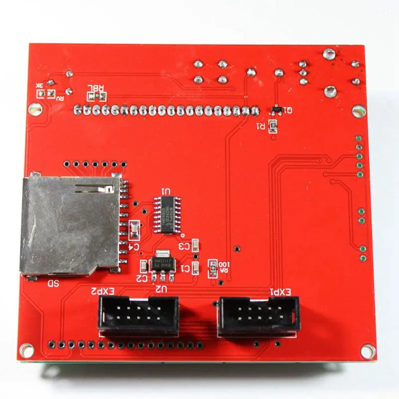
- SD Card add on available — Available now made by Kliment – Sdramps
- LEDs indicate when heater outputs on
- Option to connect 2 motors to Z for Prusa Mendel
RAMPS v1.4
RAMPS v1.3
RAMPS v1.2
Firmware and Pin Assignments
RAMPS 1.4 uses the same pin definitions as 1.3.
You will need the Arduino software to upload the firmware to Arduino Mega. The version of Arduino you need may be determined by the firmware you want to use. The current (as of 2014-01-22) Marlin firmware is compatible with Arduino version 1. 0.5. Some other firmwares may require Arduino software version 0023, NOT the most recent version. Please see your firmware documentations if you need assistance.
Troubleshooting: You may need to make sure that the driver is installed for the Arduino MEGA by going to Control Panel -> Hardware and Sound -> Device Manager. If the device that appears/disappears when you plug in and unplug the board USB is “Unknown Device” under “Other devices”, then you need to right click on the device and click the update driver button. Find where on your computer you saved/installed the Arduino software, and tell the wizard to search in the driver folder there. Windows 8 will give this error: “The third party INF does not contain digital signature”. If so, save the zip for the latest version of Arduino on your PC, and repeat the steps above with the driver folder in there. It should contain the digital signature Windows needs.
Sprinter and Marlin are popular and stable firmwares for RAMPS as of 3/28/2012.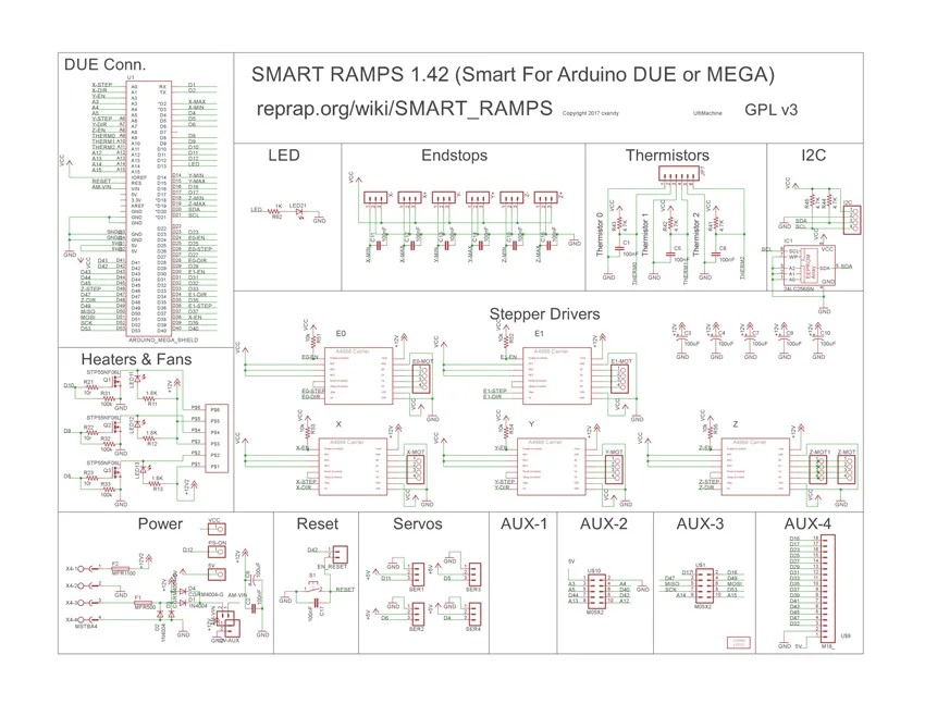 Pronterface is a cross platform printer control program that can be used for testing/printing.
Working preconfigured Marlin firmware can be downloaded. is for mechanical endstops. For optical, you will need to reverse the endstop logic in configuration.h. The language of display is in italian, but can easy be changed in language.h. It is preconfigured for the RepRap Discount Smart Controller and similar LCD module. You will need to disable LCD in configuration.h if not using it.
Others (Need pins set in Firmware as below):
- mechanical endstops (now the default ultimachine.com option) require #define OPTO_PULLUPS_INTERNAL 1 to be added to configuration.h if not there by default.
Here are the pin definitions for this board:
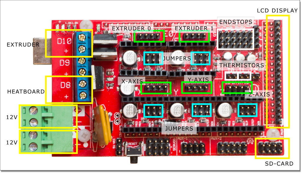
RAMPS 1.4 Pinout
// For RAMPS 1.4 #define X_STEP_PIN 54 #define X_DIR_PIN 55 #define X_ENABLE_PIN 38 #define X_MIN_PIN 3 #define X_MAX_PIN 2 #define Y_STEP_PIN 60 #define Y_DIR_PIN 61 #define Y_ENABLE_PIN 56 #define Y_MIN_PIN 14 #define Y_MAX_PIN 15 #define Z_STEP_PIN 46 #define Z_DIR_PIN 48 #define Z_ENABLE_PIN 62 #define Z_MIN_PIN 18 #define Z_MAX_PIN 19 #define E_STEP_PIN 26 #define E_DIR_PIN 28 #define E_ENABLE_PIN 24 #define SDPOWER -1 #define SDSS 53 #define LED_PIN 13 #define FAN_PIN 9 #define PS_ON_PIN 12 #define KILL_PIN -1 #define HEATER_0_PIN 10 #define HEATER_1_PIN 8 #define TEMP_0_PIN 13 // ANALOG NUMBERING #define TEMP_1_PIN 14 // ANALOG NUMBERING
| 1 2 3 4 5 6 7 8 9 10 11 12 13 14 15 16 17 18 19 20 21 22 23 24 25 26 27 28 29 30 31 32 33 34 35 36 | // For RAMPS 1. #define X_STEP_PIN 54 #define X_DIR_PIN 55 #define X_ENABLE_PIN 38 #define X_MIN_PIN 3 #define X_MAX_PIN 2
#define Y_STEP_PIN 60 #define Y_DIR_PIN 61 #define Y_ENABLE_PIN 56 #define Y_MIN_PIN 14 #define Y_MAX_PIN 15
#define Z_STEP_PIN 46 #define Z_DIR_PIN 48 #define Z_ENABLE_PIN 62 #define Z_MIN_PIN 18 #define Z_MAX_PIN 19
#define E_STEP_PIN 26 #define E_DIR_PIN 28 #define E_ENABLE_PIN 24
#define SDPOWER -1 #define SDSS 53 #define LED_PIN 13
#define FAN_PIN 9
#define PS_ON_PIN 12 #define KILL_PIN -1
#define HEATER_0_PIN 10 #define HEATER_1_PIN 8 #define TEMP_0_PIN 13 // ANALOG NUMBERING #define TEMP_1_PIN 14 // ANALOG NUMBERING |
 4
4Voltage and current notes
Standard RAMPS has a 5A PTC fuse that runs the Arduino Mega, the stepper motor drivers, and the D10 and D9 outputs. This PTC fuse is rated for a max of 30V, however other components on the board are rated for lower voltages, so care should be taken when using any voltage >12V.
Standard RAMPS has a 11A PTC fuse that runs the D8 output. This PTC fuse is rated for a max of 16V.
RAMPS was developed with 12V systems in mind, but it is possible to run it at 24V with various precautions. Most RAMPS boards will happily run at 13.8V or slightly higher with no modification. It is not recommended to exceed 15V for a standard setup, especially if you’ve bought your board from a cheaper supplier who may have used lower spec components than are recommended.
Notes:
- Some variants of RAMPS have real fuses in place of the PTC fuses (eg: GRRF RAMPS). The max current limits will of course be different.
- Many PSU’s overestimate their max current capability. The max current you require will depend on all your components and the voltage you run them at. For a standard RAMPS board, running a machine with a heated bed, your PSU should generate 12V at >16A (20+A is better, as some PSU’s overestimate their capabilities).

Stepper Driver Boards
Jumpers need to be installed under each stepper driver:
For now the default is 1/16 micro stepping (all jumpers installed under drivers)
RAMPS is quite happy with the 12 V line from PCPowerSupply. Or you can hack up a 12V laptop power supply, or other 12 V “wall wart” power supply. Make sure that the power supply can output 5A or greater. Additional 11A may be needed for heated bed support.
See Connecting power above.
The 3 pins next to the reset switch are meant to optionally connect to your PSU.
The PS_ON pin is intended to switch your power supply on and off. Many firmwares support pulling this pin low with M80 command to turn the power supply on, and M81 to turn it off. This behavior is desired for ATX power supplies and can be modified in firmware to support 5V high power supplies like those borrowed from an Xbox.
Without D1 installed, or when the 12VIN is not connected, the Arduino gets its power from USB. If you want your kit powered without USB connected you need to solder in D1 OR connect VCC to your PSU.
The VCC pin can be connected to your ATX’s 5Vsb to continuously power the Arduino from your ATX power supply. You will want to make sure that D1 is not installed or cut out. The Arduino is not designed to be powered directly on the VCC rail and the VIN pin at the same time.
If you want to use PS_ON to turn on your power supply then don’t use diode D1, you need your Arduino to be powered from 5Vsb otherwise when no USB is connected the PS_ON pin floats (and your power supply pulses on and off).
The 5V pin in that connector on RAMPS only supplies the 5V to the auxiliary servo connectors. It is designed so that you can jumper it to the VCC pin and use the Arduino’s power supply to supply 5V for extra servos if you are only powered from USB or 5V. Since there is not a lot of extra power from the Arduino’s power supply you can connect it directly to your 5V power supply if you have one. You can also leave this pin not connected if you have no plan to add extra servos.
Maximum Input Voltage
Power Supply without diode
There are three limiting factors to the maximum voltage that you can put into the RAMPS:
- The Arduino Mega maximum input voltage
- Filtering capacitor maximum voltages
- PTC fuse maximum voltages
First, the 1N4004 diode connects the RAMPS input voltage to the Arduino Mega which has a recommended maximum input voltage of 12 volts. If your board does not have this diode soldered in (or if you cut it), you will need to power the Mega through the USB connector or through a separate 5v line, but this allows a higher RAMPS voltage.
Second, most boards use 25v or 35v aluminum electrolytic capactors (C2, C3, C4, C6, C7, C9, and C10). To be safe, you should only go to half of your rated maximum voltage — thus if your board has 35v capacitors (code VZA) then you should use a maximum input of 17.5v. The absolute maximum voltage is determined by the pololu servo drivers, which themselves are limited to 35V.
Third, the MF-R500 (5A) PTC fuse is rated to 30V and the MF-R1100 (11A) PTC fuse is rated to 16V. They will need to be replaced with real fuses.
Power Supply with diode
If your board has a 1N4004 diode soldered in, do not apply more than 12 V to it. Original flavor Arduino Mega are rated to 12 V input. While Arduino Mega 2560 can take 20 V, it is not recommended.
Troubleshooting
- Check List
- RAMPS shield firmly seated on Arduino MEGA
- No stray wires/metal to cause short
- All connections firmly seated, screws tight
- Power connection oriented correctly, connected to RAMPS shield (only USB is connected to MEGA)
- Thermistor connected to T0
- Firmware uploaded
- Stepper driver potentiometers to a sane setting (maybe 25% from CCW to start, adjust to enough power to drive axis + not overheat)
- Heater wires properly connected
- Power supply functioning properly
- Cannot connect?
- Verify firmware and host software baud rate matches
- Disconnect USB, reconnect, and retry
- It may be a problem with the software you’re using (repsnapper).
 Try using pronterface.
- Stepper motor getting too hot?
- Adjust the potentiometer (small screw) on the stepper driver in question by rotating the screw counterclockwise to decrease the current going to the stepper motor.
- My fan is not working.
- If you have RAMPs 1.3+ and sprinter firmware (set with the default pins for RAMPs 1.3), try attaching the fan to D9 output.
- In pronterface, the fan can be turned on by using the M106 command and turned off with M107.
- Hot end/heated bed not working.
- Check resistivity by disconnecting from RAMPs and measuring with multimeter
- Check that host software obtains readings from thermistors
Known issues and limitations
1. Overheating 5V regulator on the Arduino Mega
Unless you provide external 5V power or provide 5V through USB cable, the regulator on the Arduino supplies 5V power to the Arduino, the RAMPS (which uses very little) and anything else connected to it.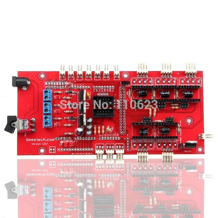 With nothing else powered from the RAMPS, the voltage regulator will run quite warm but not overheat (in tests, I was even able to turn up the input voltage from 12V to 15V without overheating it). With a 20×4 LCD connected, it’s still OK with 12V input. However, if you power a servo or a graphic LCD from the RAMPS, then you will almost certainly overheat the voltage regulator. The usual symptom is that the system will not work unless it is connected to a PC via USB. Or the system may work for a few minutes, hours or days, then fail.
Workarounds include (a) removing D1 on the RAMPS and providing external 5V power to the Arduino/RAMPS; (b) driving the backlight of the graphical LCD from 12V through a series resistor instead of from 5V (a 120 ohm 1W resistor is about right for 12864-type displays), (c) using an Arduino variant with a more powerful voltage regulator (e.g. Taurino).
2. Overheating bed heater MOSFET
The STP55NF06L mosfet is not really adequate to drive a 10A heated bed without a heatsink, so on boards supplied without a heatsink it runs very hot.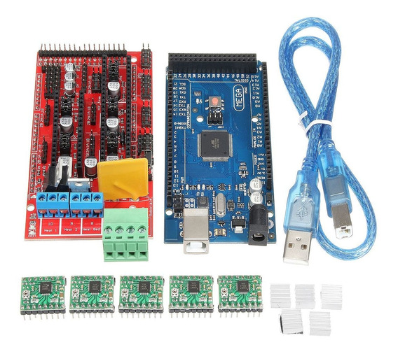 This is often exacerbated by the previous issue (overheating 5V regulator), which causes the voltage on the 5V rail to be significantly lower than 5V and insufficient to turn the mosfet fully on.
Workaround: either add a heatsink, or (preferably) replace the bed heater mosfet (Q3) by a better type such as IRLB8743PBF or IRLB3034PBF. Also check that the voltage on the 5V rail is close to 5V, preferably at least 4.75V.
3. USB data rate fails to keep up with the printer, resulting in slow, poor-quality prints
This is due to the lack of a true USB port on the Arduino Mega, which uses USB-over-serial instead, and the consequent lack of driver-level flow control. As a result, flow control has to be done at application level by the host program waiting to receive “OK” after sending each command. General purpose host operating systems such as Windows and Linux cannot do this efficiently. Some host programs and operating system combinations work better than others, but this issue has even been reported by some users running Octoprint on a dedicated Raspberry Pi host.
Workaround: print from SD card instead of over USB.
Change Log
- 1.4.2 has minor changes over RAMPS 1.4. The RAMPS 1.4.2 has below enhancements over 1.4
- Standard blade fuses instead of thermal fuses increasing the heat resilience.
- Current carrying improved by increasing the thickness of the cooper at the PCB from 35 to 70 micro meters.
- Suppression caps added to each end-stop to avoid spurious signals.
- Added an additional connector to XY, E1 and E2 to connect a second stepper motor.
- Connector for external reset added.
- Labeled D8, D9,D10 with Heatbed, Extruder 1 Fan and Extruder 2.
- 1.4 August 4, 2011
- Changed capacitors and resistors to surface mount components
- Added LEDs to mosfet outputs
- Added bulk capacitors for each stepper driver
- Added pull up resistors to enable to override the Pololu drivers default enabled state
- Added mosfet gate resistors
- Added pull-ups for I2C
- Servo1 connector moved to pin 11 to free 7 for ADK
- Fixed thermals
- Servo 5V supply is only connected to VCC if a jumper is added
- Reset switch changed for small footprint
- Moved Aux conectors around a bit and increased board size ~0.
 1″
1″ - Added some space around Q3 for a small heatsink
- 1.3 May 13, 2011
- Added 5th stepper driver socket
- Added 3rd thermistor circuit
- Added Heated bed circuit w/ 11A PTC fuse, changed to 4 position pluggable input jack to accommodate additional current
- Increased board size to 4″x2.32″
- Pin order on heater outputs changed
- Increased spacing increased to accommodate different connectors
- Added connectors for optional 2 motors on Z driver
- Added connector for PS control
- Improved expansion connector layout
- Moved LED towards corner and added resistor to LED circuit
- No longer optimised for home etching :(
- License changed to GPL v3 or newer
- v1.2 January 04, 2011
- Added 0.1″ motor connector to RAMPS for each driver (motors no longer have to be connected on top of stepper drivers)
- Added breakouts for serial and I2C
- Changed extra power and pin headers around for easier connection to extra boards.
- Lost most extra analog breakouts
- More silk screen and bottom layer fixing
- v1.1 September 30, 2010
- Replaced power barrel jack with plug-able screw terminal
- Added jumpers to select micro-stepping on stepper driver boards
- Added debug LED
- Changed mosfet pins to be compatible with FiveD firmware
- Reduced number of 100uF capacitors to 1
- Added 100nF capacitor to 12V input
- Put auxiliary 12VIN and GNDIN pads in a straight line
- Silk screen and bottom layer cleaned up
- v1.0 Original RAMPS PCB design
- v0.1? Point to point wired Arduino MEGA Prototype shield
Bronnen: reprap.org
RAMPS 1.4 3D Printer Controller Board Arduino Mega Shield
Motor Driver Circuits
₹295.00Excluding tax
RAMPS 1.4 3D Printer Controller Board Arduino Mega Shield quantity
Category: Motor Driver Circuits Tags: Controller Board Arduino, Mega Shield, RAMPS
Add to wishlist
Share with Friends
- Description
- Reviews (0)
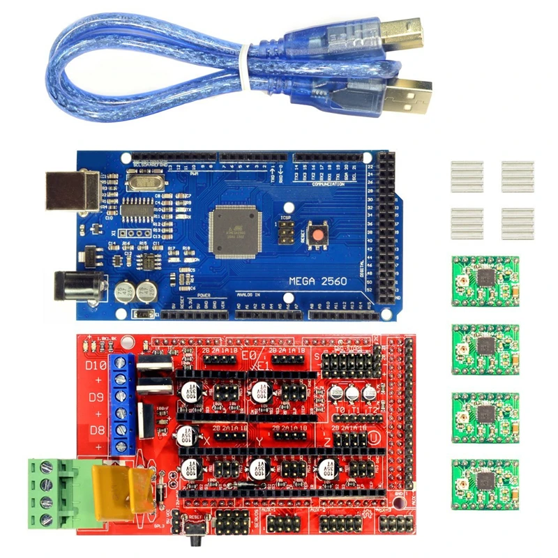
The RAMPS 1.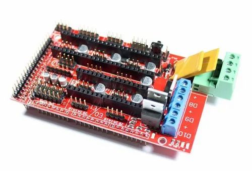 4 3D Printer Controller Board Arduino Mega Shield is designed to fit the entire electronics needed for a RepRap in one small package for low cost. RAMPS interfaces an Arduino Mega with the powerful Arduino MEGA platform and has plenty of room for expansion.
RAMPS can only work when connected to its motherboard Mega 2560 and A4988/DRV8825. Owning to its stability in operation and great compatibility with the most 3D printer (all RepRap-model such as Prusa i2 and i3). The combination of Ramps1.4 + MEGA2560 + A4988/DRV8825 is becoming a mainstream of DIY 3D printer control board.
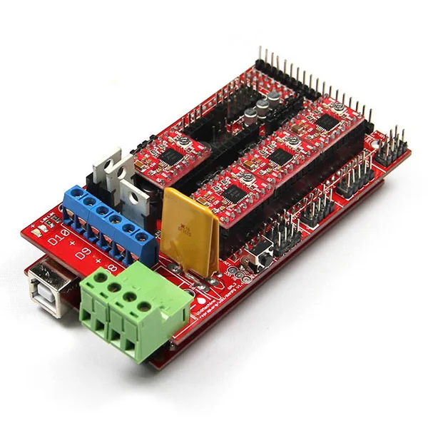
The modular design includes the plug in stepper drivers and extruder control electronics on an Arduino MEGA shield for easy service, part replacement, upgrade-ability, and expansion. Additionally, a number of Arduino expansion boards can be added to the system as long as the main RAMPS board is kept to the top of the stack.
Additionally, a number of Arduino expansion boards can be added to the system as long as the main RAMPS board is kept to the top of the stack.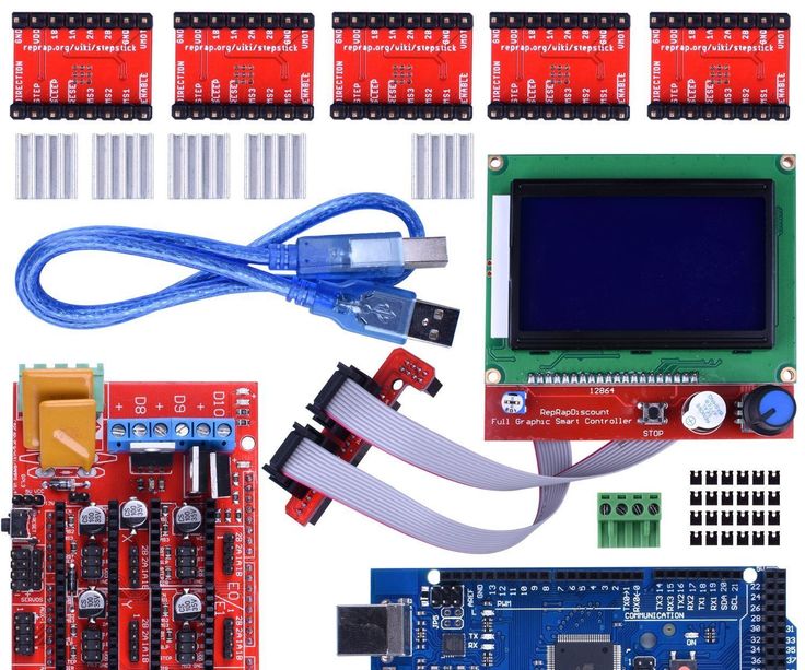 Ramps boards are the heart of most DIY 3D printers on the market and a nice clean compact way to integrate all the systems into a compact enclosure mountable format.
Specifications :-
- Supply Voltage: 12V
- Standard interfaces (as that of the extruder)
- Reserved GCI like I2C and RS232
- 3 MOSFET’s are applied to the heater/ fan and thermistor circuit.
- Another 5A added to protect the component parts.
- An 11A fuse is added to the hotbed.
- Support 5 stepper drive board
- The adoption of Pin Header as Pololu makes it more convenient to repair or change.
- I2C and SPI are reserved for expanding
- All the MOSFET can be controlled by PWM
- Use the interface of the servo motor to adjust the level of the printing platform automatically.
- Adding an SD module for SD ramps module.
- LED can indicate the status of the heater (the open and close of MOS).
- Expandable to control other accessories.
- Pololu boards are on pin header sockets so they can be replaced easily or removed for use in future designs.
- 2 stepper motor for Z axis in parallel.
* product image for illustration purposes only. actual product may vary.
Only logged in customers who have purchased this product may leave a review.
You may also like…
-
A3967 Stepper Motor Driver Module
₹165.00Excluding tax Add to basket -
12K ohm Resistor – 1/2 Watt – 5 Pieces Pack
₹6.00Excluding tax Add to basket -
USB A Male to mini B Cable – Cable for Arduino Nano
₹39.00Excluding tax Add to basket -
L298 2A Dual Motor Driver Module with PWM Control
₹125.00Excluding tax Add to basket -
Hot Melt Glue Gun – 60 Watt
₹295.00Excluding tax Add to basket -
Raspberry Pi 4 Model B with 4GB Ram Starter Kit
₹9,999.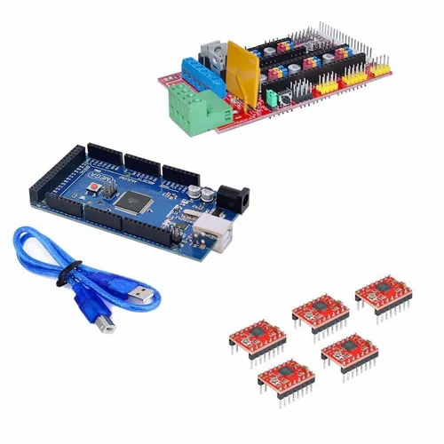 00Excluding tax Read more
 -
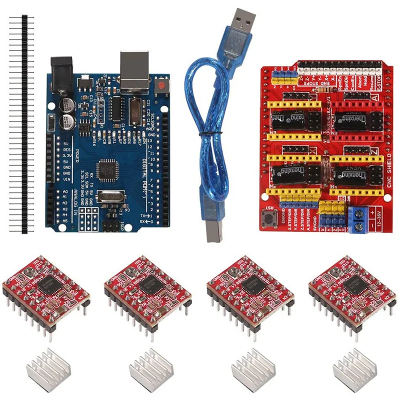
CNC Shield V3 – Engraving Machine 3D Printer A4988 DRV8825 Driver Expansion Board
₹139.00Excluding tax Add to basket
Answers to questions on ramps 1.6
For questions specifically related to the RAMPS 1.6 controller board - The RepRap Arduino Mega Pololu Shield, or RAMPS for short, is an Arduino Mega expansion shield designed to house all the electronics for a RepRap 3D printer in a small, inexpensive package.
The RepRap Arduino Mega Pololu Shield, or RAMPS for short, is an expansion shield for the Arduino Mega designed to house all the electronics for a RepRap 3D printer in a small, inexpensive package. nine0003
RAMPS 1.6 is the second iteration of RAMPS released by BIQU/BIGTREETECH. It replaces the original green power connector with a pair of screw terminals, adds a larger heatsink on top of the MOSFETs, and has a larger desktop MOSFET. It supports surface mounted fuses and built-in RAMPS 1.5 MOSFETs.
In addition, the positions of diodes D1 and D2 are reversed compared to the positions in ramps 1.4, diode D1 is now the diode closest to fuse F2. The same applies to RAMPS 1.5 also manufactured by BIQU/BIGTREETECH. nine0003
See the RAMPS RepRap wiki for more information and a complete list of features.
- Is it possible to solder the power connections from a partially burnt board I recently had a RAMPS power connector on fire while heating a heated table. I suspect it was a defect caused by the connector and unsoldered/removed it as best I could. I am not an electrical engineer…
- Maximum current, voltage and power input values for RAMPS 1.4, 1.5 and 1.6? nine0015 I need to know the maximum input current, voltage and power for: RAMPS 1.4 RAMPS 1.5 RAMPS 1.6 I want to build a homemade 3D printer. RAMPS 1.6 can only deliver 270W. But if...
- New RAMPS 1.
 6 not working I just bought a new RAMPS 1.6 shield to replace my old RAMPS 1.4 shield. The problem is that it just doesn't work, the motors don't move, the thermal pad/nozzle doesn't get hot. All this…
 - Will the TMC2130 V3.0 stepper driver work with the Ramps 1.6 Plus board? nine0015 I want to buy onboard RAMPS 1.6 Plus. The description in the link says it is compatible with the TMC2130 driver, but I found that there are two versions soldered in SPI mode. BIGTREETECH TMC2130 V3.0 .…
- RAMPS 1.6+ steppers not working I recently bought a RAMPS 1.6+ and it connects just fine to the Arduino Mega 2560. I can use the Pronterface to heat the extruder and heated bed, but the motors refuse to work. U…
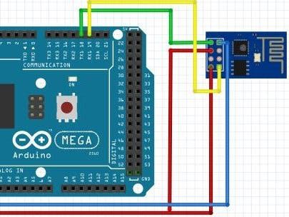
- How do I connect a separate 5V supply to an Arduino connected to a RAMPS board? nine0015 Going to add a Raspberry Pi to my printer which requires a 5V supply. I want to take this opportunity to also power an Arduino with the same supply as the 12V drop…
- How do I connect power and fan to RAMPS 1.
 6? My RAMPS 1.4 card has failed. I bought RAMPS 1.6 to replace it but : The old board had 4 power wires that went to 5A and 11A respectively. RAMPS 1.6 only has 1 pair...
 - Is 12V and 15A enough to make RAMPS 1.6 Plus and two stepper motors work? nine0015 I want to place an order with this configuration Arduino MEGA 2650 R3 RAMPS 1.6 Plus 2 TMC2130 2 stepper motors 17hs3401 1 fan But I'm not sure what voltage and current...
- I can set the voltage and current of the TMC2130 driver manually. But in what cases can some components burn out? I need to know if something burns out in advance, I connect all the circuits: RAMPS 1.6+ Arduino Mega 2560 Power supply 12 V, 15 A 2 TMC2130 V3.0 Stepper Motor Driver 2 Stepper Motors…
- Which 3D printer controller should I use? I recently built a 3D printer from scratch and used an Arduino Mega + RAMPS 1.4 to control it. A few weeks later I installed a heated table so my prints would stick better on…
- RAMPS 1.
 6 power connector caught fire when the table was heated I built a 3D printer from scratch, initially using a RAMPS 1.4 shield with an Arduino Mega as the controller. About a week after the printer was finished and working well, I installed the table...
 - TMC connection error; SSD1306 I have some problems with my small I2S SSD1306 OLED drive. When enabled in Marlin 2.0.1 it shows a great buuuut with a bottom line saying TMC CONNECT ERROR. …
- Replacing RAMPS 1.4 with 1.6 While building my printer I accidentally shorted the RAMPS 1.4 board, while looking for a replacement I found RAMPS 1.6 which would eliminate the need for a MOSFET power module. My question is, can I just…
- Short circuit on the RAMPS 1.6 board? I have a board for RAMPS 1.6. After soldering the stepper drivers, I checked them for bridges and found a short where it shouldn't be. Going deeper into this, the multimeter shows ...
How to implement Arduino NANO as RS-232 to USB adapter (or need Arduino Mega?) to communicate with 3D printer (arduino uno)
arduino uno arduino mega arduino nano nine0003
I have a computer upstairs running a slicer program for 3D printing (Simplify 3D). In the basement, I have several USB enabled 3D printers. My computer upstairs has a USB to RS-232 serial adapter. The serial side of this USB-to-Serial adapter connects to the serial port of the Moxa Nport 6150 RS232-to-Ethernet protocol adapter. I get these moxa machines for free when they break down at work and then fix them for a couple of dollars.
The other side of Moxa connects to my home network router. In the basement, I can connect another Moxa to the ethernet cable on my home network, and I need to connect the RS232 serial output to the 3D printer's Micro-USB connector. How can I use an Arduino Nano (or Uno or Mega if required) to convert RS232 data to my 3D printer's USB input? nine0003
So I have PC->(RS-232)->[MOXA(RS-232)->Moxa(Ethernet)]->Router->[Moxa(Ethernet)->Moxa(RS-232)] ->[Arduino(RS-232)->Arduino(USB)]->3D Printer(via USB)... How can I make Arduino do this function? The elements in brackets [ and ] are separate devices that perform protocol conversion.
I know people use a Raspberry Pi and a program called OctoPrint to remotely control their 3D printers, but I get Moxes for free and Uno or Nano are very cheap. RPIs are more expensive, and for a few 3D printers, they can start to add up. Any ideas? nine0003
@ABNormal, 👍1
Talk
3 answers
▲ 1
The Nano, like the Uno, has a built-in USB serial converter. If you can get a serial logic level from Moxa, then you can use Nano to convert it to usb:
- Upload the "do nothing" sketch to Nano
- Connect Moxa TX to Nano Tx through a 1 kΩ resistor, and Moxa RX to Nano RX. nine0017
Yes, the second step looks back. The reason is that the RX labels and TX refer to the ATmega328P that runs your sketches on the Nano. Internally, a pin labeled RX is connected (through a resistor) to TX pin of USB serial converter and this is thus the pin you want connect to RX Moxa.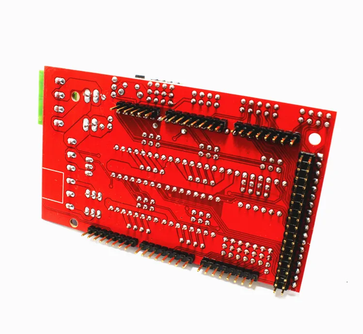 And similarly for the pin TX label (this RX on-board converter).
Step 1 is important because you don't want the 328P to open your serial port. The resistor is needed for a short time when 328P starts the bootloader and has an open serial port. nine0003
, @ Edgar Bonet
▲6
It's not as easy as you think. An Arduino will not be enough to connect a USB 3D printer. The USB protocol is strictly divided into slaves and masters. USB(us) has exactly one master, which has complete control over what the slave can do. The slave himself can do little by himself.
Your 3D printer is a USB slave device. This allows a USB master (such as a computer) to control it. The Arduino is also a USB slave device. If you connect both, then you have a USB connection without a master. Nothing will happen. So you need to implement a USB master on Arduino that can handle UART communication; everything is in the software. It's generally possible, but I wouldn't recommend it. Also, you definitely need additional hardware because D+ and D - on USB are also electrically completely different from TTL RX and TX lines (as well as from RS232 lines). They work differently. So for this you need additional hardware. nine0003
The easiest way with Arduino is to buy a USB host shield. With this you can build what you want.
But I would argue if it really makes sense. The cheapest Arduino USB host shield I could find on amazon costs about 10 euros, plus the price of the Arduino and the hassle of running it. RaspberryPi Zero W costs only 10 euros. If you don't want to use Wi-Fi, you can add a USB to Ethernet adapter. And depending on the software you're using and how it's installed, you might even be able to handle multiple printers with just one Pi (I'm using a Repertier server, which I think has the ability to manage multiple printers). (Although depending on the number of printers and the resulting workload, you can increase the game to a full Pi4)
There may be an additional method, depending on your printers. The printer microcontroller board can break the TX and RX pins for you. Then you could connect an Arduino to them, in which case there is no need for USB. But that might not be an option. If the microcontroller being used has a direct USB interface, there are no RX and TX pins to break out.
, @ chrisl
▲ 1
At the moment there is not enough information to give a general solution. As crystal rightly says, 3D printers expect a connection from a host. This host connection depends on whether the USB serial interface is supported inside the printer. These are usually FTDI or WCH (QinHeng) chips, and each type requires an appropriate system driver.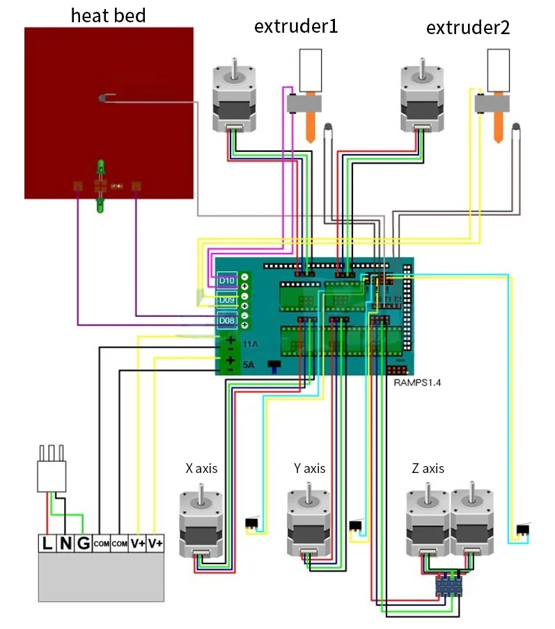 This would be difficult to implement on an Arduino USB host shield.
Most 3d printers are basically an Arduino inside. The typical 8-bit controller on the vast majority of 3d printers uses a very similar ATmega microcontroller. Some newer machines use 32-bit ARM microcontrollers which typically have 3.3V logic compared to Arduino's (typical) 5V. To add a standard RS-232 port, you need to find the RX, TX, GND, and Vcc points on each board printer controller and connect the correct pins on your RS-232 to TTL converter boards to these points. This would completely bypass USB ports on printers. nine0003
You may experience flow control and buffering issues when sending multiple ports from one PC and serial network latency. Marlin-style Gcode printers (= most filament printers that aren't Makerbot or Flashforge, roughly) don't use flow control: the printer sends back ok when it's ready for the next command. 3D printers don't need really fast serial connections (less than 20kbps per printer if they use Gcode), but they do need data when they're ready to print.