Alunar 3d printers
Alunar M508 3D Printer Kit
Alunar M508 3D Printer Kit - Ships from USA
Alunar
- $21500
- Save $84
Default Title - Sold Out Quantity
- Info
- Why buy from us?
- Shipping
- Price Guarantee
Free 0.25kg PLA filament
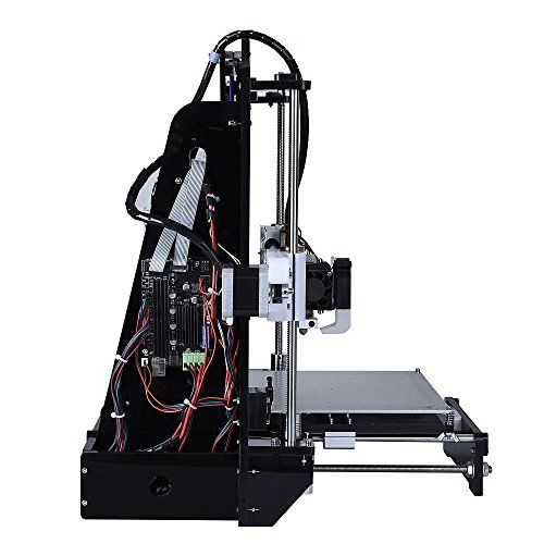
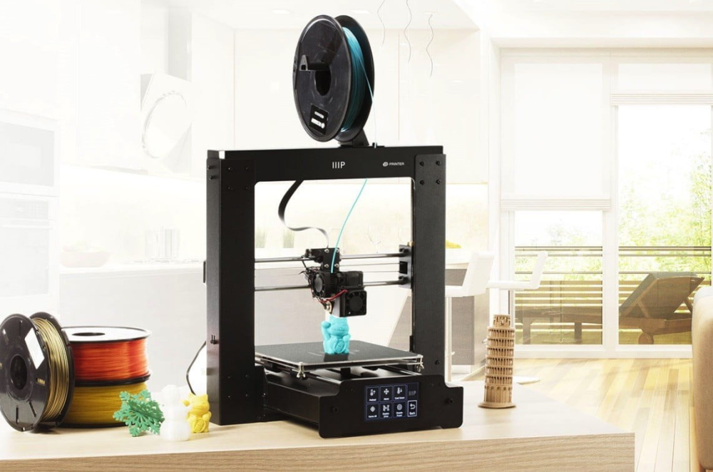
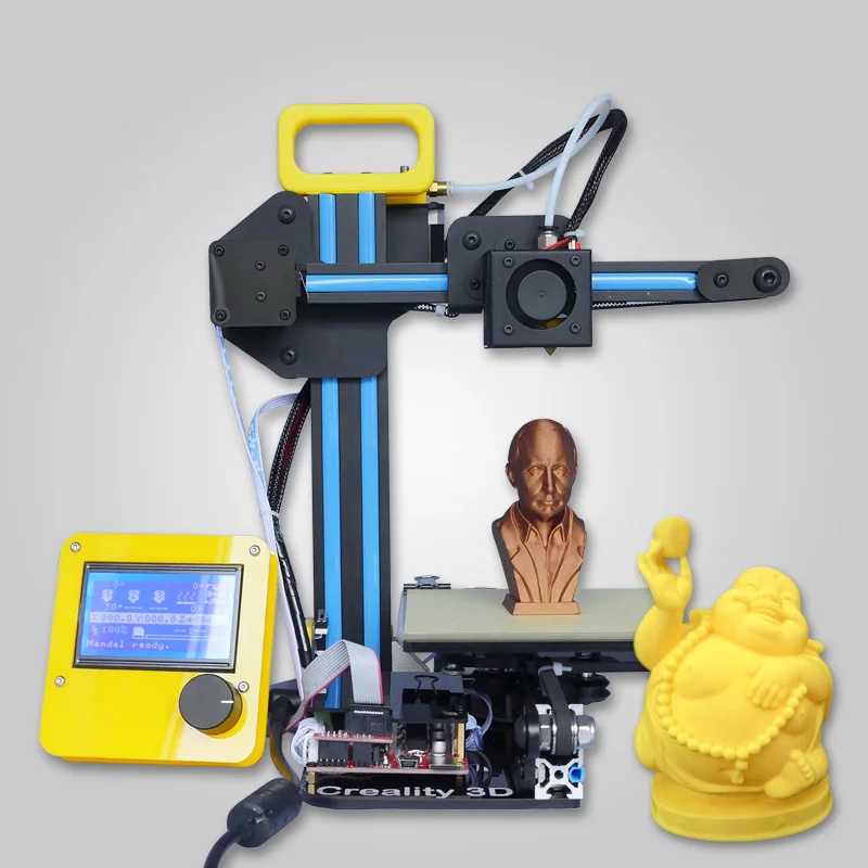
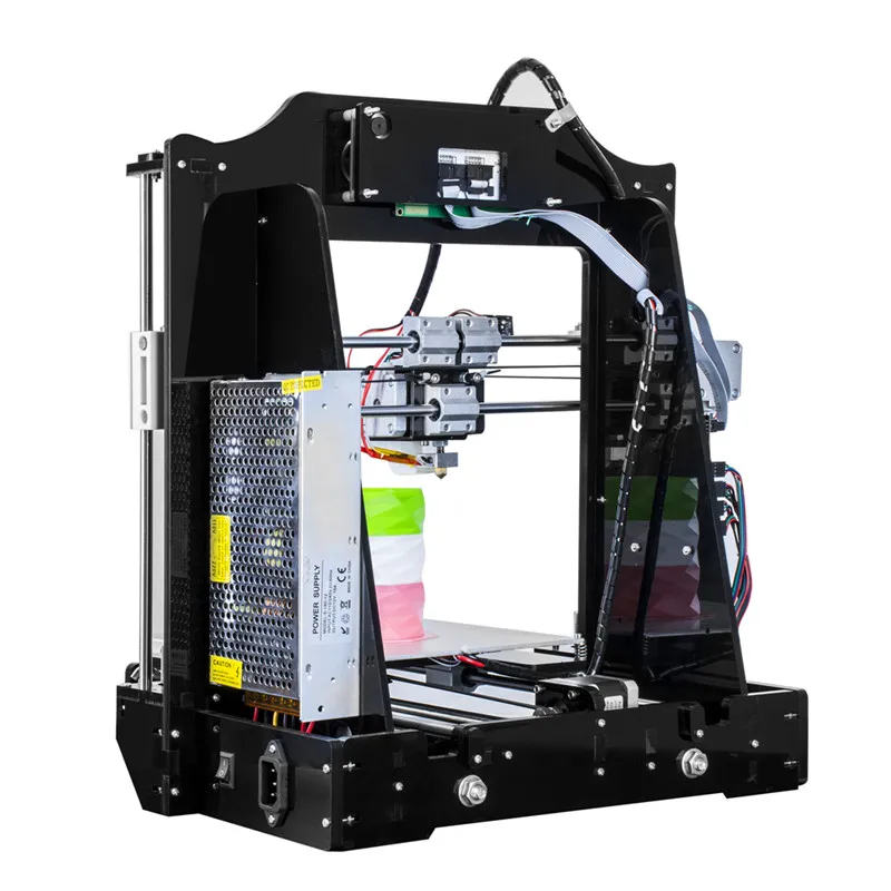
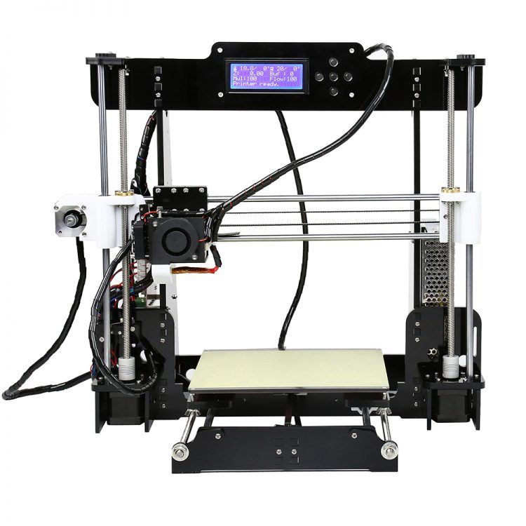
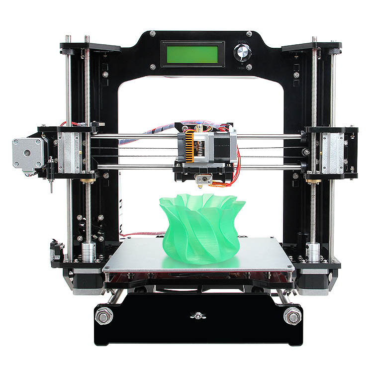
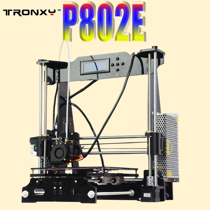
This Alunar® M508 3D Printer is the amazing king of the Prusa I3 family.This unassembled 3D printer is a new DIY kit which will feature the superior quality, performance, accuracy and most important, best affordability in desktop 3D printer market. And it is easy and quick to build up if you follow the detailed users’ assembly and manual guide. With more flexible and humanistic software system, it is convenient and fast for you to install and uninstall the filament. More importantly, you can also get the simple-combined and colorful printing works by changing the filament when the printer is working. And it can be equipped with as wee as the 0.3mm extruder to ensure its superior quality and high accuracy. Welcome to chose this late updated printer with best performance.
Features
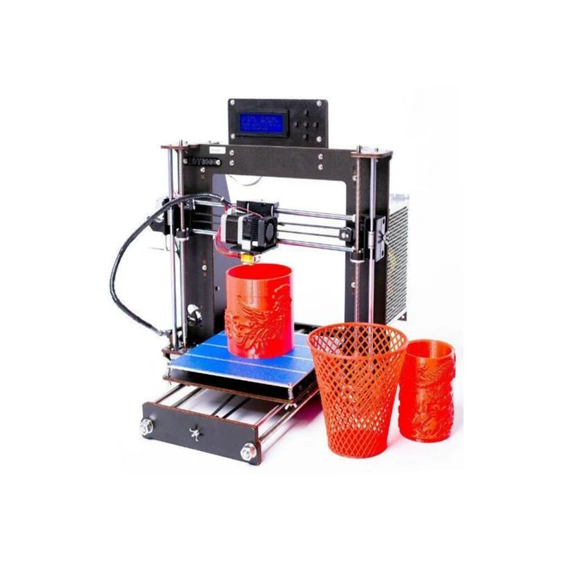
- LCD Filament Acrylic 3D Printer; Supports ABS/PLA/Wood/Flexible PLA/Nylon Filament
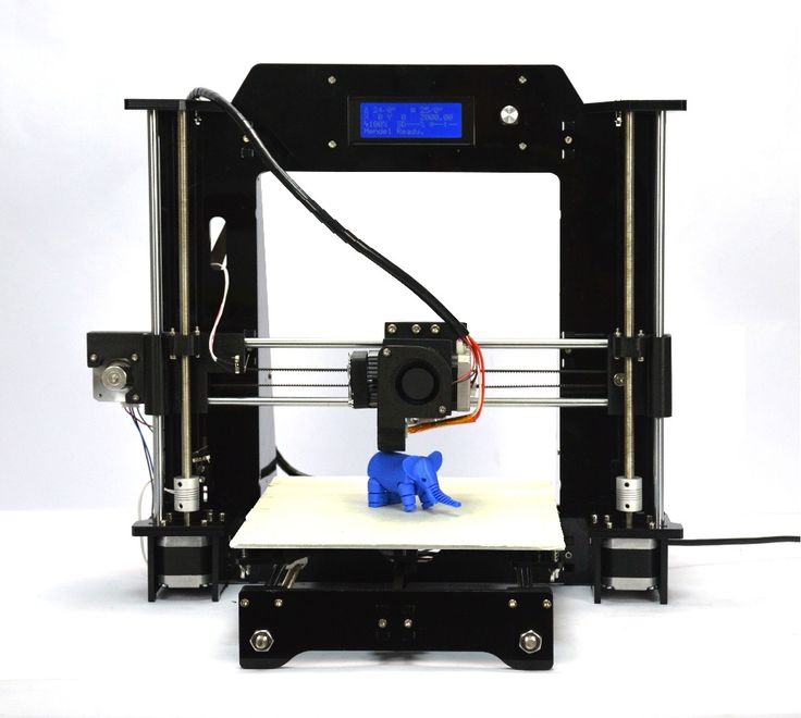
- Updated function:Auto Install and Uninstall filament function.When you choose to change filament, the 3D printer will auto uninstall the filament, you no need pull the filament so hard.
- It is unassembled DIY kit, provide you an unforgettable step-by-step learning experience of 3D printer from scratch.
- Alunar 3D printer supports multi colors printing for one item.When printing,can change filament,to print by different colors 3D filament.
- 0.3 mm 3D printer nozzle, make the printing much more elaborate. Mould parts for Z axis and three slide blocks for extruder make the printer much more stable.
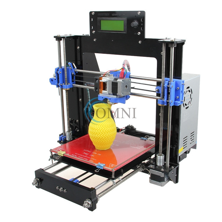
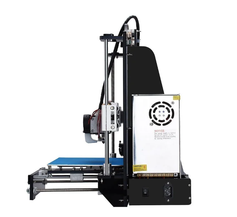
- The power supply for the Alunar DIY 3D printer M508 is 110 V/220 V, you can switch it to fit your needs.
Specification
| Frame Material: | Acrylic |
| SD-Card & LCD Screen: | Yes |
| XY Axis Accuracy: | 0.011mm |
| Z Axis Accuracy: | 0.004mm |
| # Extruders: | 1 |
| Print Color: | Single |
| Extruder Diameter: | 0.4mm |
| Printing Speed: | 120mm/s |
| Max. Print Size: | 200*200*180mm |
| Nozzle Temp.: | 210C, Max 260C |
| Heating Bed Temperature: | 50-100C |
| Heating Plate Material: | Aluminum |
| Printable Materials: | PLA, ABS, HIPS, Wood Polymer, PVA, PP, Luminescent, Nylon |
| Filament Diameter: | 1.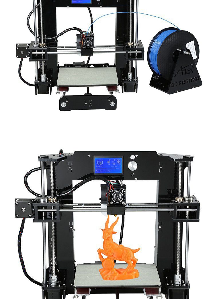 75mm 75mm |
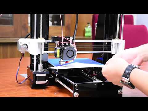
Assembly Videos
| 1.Pre Test before Assembly | 5. Printer Instruction Step 4 |
| 2.Printer Instruction Step 1 | 6. Printer Instruction Step 5 |
| 3. Printer Instruction Step 2 | 7. Printer Instruction Step 6 |
| 4. Printer Instruction Step 3 | 8. Printer Instruction Step 7 |
Drivers
You will get the device driver from the SD Card also coming with your printer kit. There is two driver respectively compatible with the MAC and WIN system, which will provide the best choice for the correct driver suited with your computer. And you just need to connect the SD card to your computer and click the driver software and it would only take few minutes to be installed automatically.
M508 Driver
ALUNAR M508 Quick Start Guide
How to download firmware
Price match guarantee:
We work very hard to ensure that we offer the absolute best prices online for all of our printers including Tevo 3D printer kits. If you find another online store that offers a lower price than us on Tevo 3D printers for sale, please let us know and we will refund your original payment for the difference. Read More
30 day price assurance guarantee:
We want you to feel confident that you are getting the absolute best price for the product. If you find that our own website has a lower price for the same item you have ordered within 30 days of your purchase date, we will refund the difference! Read More
Full manufacturer direct warranty:
We are an authorized dealer for all our products and comes with the full manufacturer warranty.
Tax free (except California and Nevada):
The price you see is the price you pay but because we operate in California and Nevada we must charge tax in California and Nevada.
Safe & secure online ordering:
We are certified Level 1 PCI DSS compliant. What this means is that we meet all the requirements defined by the Payment Card Industry Security Standards Council. For additional information on PCI Compliance, visit the PCI Compliance Guide website. We also accept payment via Pay Pal, a leader in secure online payment processing.
Best customer service:
We strive to offer the best customer service we can. If you have any questions please let us know by phone or email.
Exclusive deals:
We appreciate each and every customer that comes to our store. We know you have a lot of choices when it comes to your 3D printing purchase. That's why we'd like to show our appreciation by periodically sending out exclusive coupons and deals to our past customers!
Order Confirmation:
As soon as you place your order you will receive an order confirmation e-mail. This means that we have received your order in our system and pre-authorized your credit card for the purchase. As soon as we receive your order we automatically reach out to our suppliers to confirm that it is in stock and available for immediate shipment. If your item is on backorder or unavailable we will void the pre-authorization and reach out to you via e-mail. If your item(s) are available for immediate shipment (within 5 business days) we will process the charges and submit the order for shipment.
Order Shipment:
If your order is in stock and we process the charges to your credit card, it will ship within five business days from the date of your order. We will send you tracking information within 24 hours of your order leaving the warehouse to the e-mail address you provide when checking out. If you do not receive tracking information from us within six business days of your order feel free to follow up with us at [email protected]
Domestic Shipping:
We do not ship to P.O. Box.
International Shipping:
Please contact us for international shipping rates
We work very hard to ensure that we offer the absolute best prices online for all of our printers including Tevo 3D printer kits.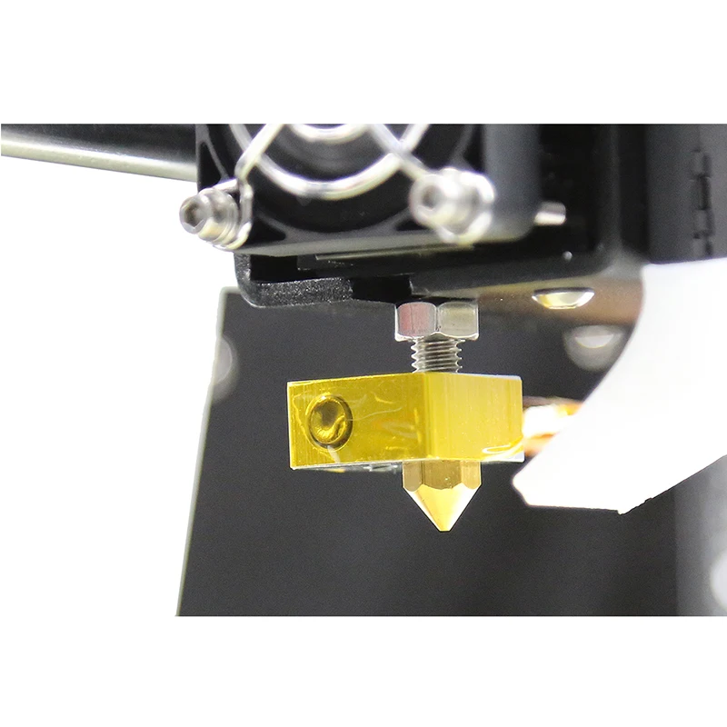 If you find another online store that offers a lower price than us on Tevo 3D printers for sale, please let us know. We want you to feel confident when you buy a Tevo 3D printer or any of our other printers that you are getting the absolute best price for the product.
To request your partial refund simply e-mail us a link to the same product on our website, or on our competitors’ website and we will process the credit accordingly.
Our 100% Price Guarantee has some limitations:
- You must purchase the item from our website before requesting your Price Match Guarantee
- Promotions such as rebates and buy one, get one free offers are not eligible
- The item must be in stock on the competitors website
- The competitor must be an online store, they may not have a retail location
- The item must ship from the same country.
- The website cannot be a discounter or auction website (ie; eBay, overstock, etc..)
- The competitor must be an Authorized Retailer for the product in question
- The Price Match Guarantee includes the item price and the shipping charges, it excludes sales tax or any customs and duties
Info▼
Free 0. 25kg PLA filament
This Alunar® M508 3D Printer is the amazing king of the Prusa I3 family.This unassembled 3D printer is a new DIY kit which will feature the superior quality, performance, accuracy and most important, best affordability in desktop 3D printer market. And it is easy and quick to build up if you follow the detailed users’ assembly and manual guide. With more flexible and humanistic software system, it is convenient and fast for you to install and uninstall the filament. More importantly, you can also get the simple-combined and colorful printing works by changing the filament when the printer is working. And it can be equipped with as wee as the 0.3mm extruder to ensure its superior quality and high accuracy. Welcome to chose this late updated printer with best performance.
Features
- LCD Filament Acrylic 3D Printer; Supports ABS/PLA/Wood/Flexible PLA/Nylon Filament
- Updated function:Auto Install and Uninstall filament function.When you choose to change filament, the 3D printer will auto uninstall the filament, you no need pull the filament so hard.

- It is unassembled DIY kit, provide you an unforgettable step-by-step learning experience of 3D printer from scratch.
- Alunar 3D printer supports multi colors printing for one item.When printing,can change filament,to print by different colors 3D filament.
- 0.3 mm 3D printer nozzle, make the printing much more elaborate. Mould parts for Z axis and three slide blocks for extruder make the printer much more stable.
- The power supply for the Alunar DIY 3D printer M508 is 110 V/220 V, you can switch it to fit your needs.
Specification
| Frame Material: | Acrylic |
| SD-Card & LCD Screen: | Yes |
| XY Axis Accuracy: | 0.011mm |
| Z Axis Accuracy: | 0.004mm |
| # Extruders: | 1 |
| Print Color: | Single |
| Extruder Diameter: | 0. 4mm 4mm |
| Printing Speed: | 120mm/s |
| Max. Print Size: | 200*200*180mm |
| Nozzle Temp.: | 210C, Max 260C |
| Heating Bed Temperature: | 50-100C |
| Heating Plate Material: | Aluminum |
| Printable Materials: | PLA, ABS, HIPS, Wood Polymer, PVA, PP, Luminescent, Nylon |
| Filament Diameter: | 1.75mm |
Assembly Videos
| 1.Pre Test before Assembly | 5. Printer Instruction Step 4 |
| 2.Printer Instruction Step 1 | 6. Printer Instruction Step 5 |
| 3. Printer Instruction Step 2 | 7. Printer Instruction Step 6 |
| 4. Printer Instruction Step 3 | 8. Printer Instruction Step 7 |
Drivers
You will get the device driver from the SD Card also coming with your printer kit.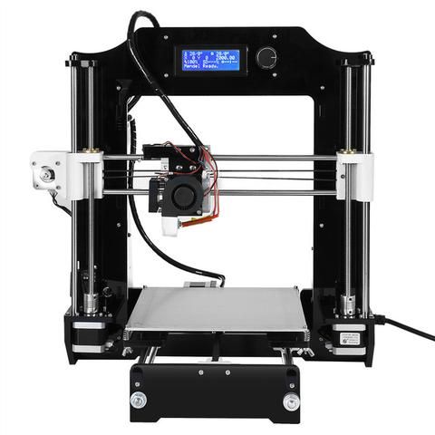 There is two driver respectively compatible with the MAC and WIN system, which will provide the best choice for the correct driver suited with your computer. And you just need to connect the SD card to your computer and click the driver software and it would only take few minutes to be installed automatically.
M508 Driver
ALUNAR M508 Quick Start Guide
How to download firmware
Why buy from us?▼
Price match guarantee:
We work very hard to ensure that we offer the absolute best prices online for all of our printers including Tevo 3D printer kits. If you find another online store that offers a lower price than us on Tevo 3D printers for sale, please let us know and we will refund your original payment for the difference. Read More
30 day price assurance guarantee:
We want you to feel confident that you are getting the absolute best price for the product. If you find that our own website has a lower price for the same item you have ordered within 30 days of your purchase date, we will refund the difference! Read More
Full manufacturer direct warranty:
We are an authorized dealer for all our products and comes with the full manufacturer warranty.
Tax free (except California and Nevada):
The price you see is the price you pay but because we operate in California and Nevada we must charge tax in California and Nevada.
Safe & secure online ordering:
We are certified Level 1 PCI DSS compliant. What this means is that we meet all the requirements defined by the Payment Card Industry Security Standards Council. For additional information on PCI Compliance, visit the PCI Compliance Guide website. We also accept payment via Pay Pal, a leader in secure online payment processing.
Best customer service:
We strive to offer the best customer service we can.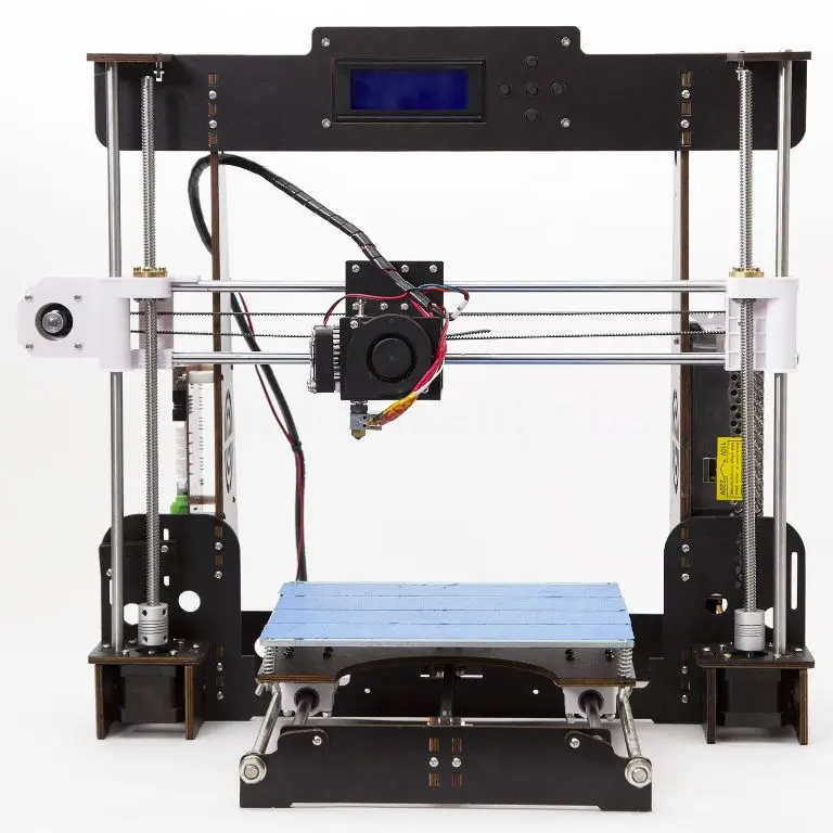 If you have any questions please let us know by phone or email.
Exclusive deals:
We appreciate each and every customer that comes to our store. We know you have a lot of choices when it comes to your 3D printing purchase. That's why we'd like to show our appreciation by periodically sending out exclusive coupons and deals to our past customers!
Shipping▼
Order Confirmation:
As soon as you place your order you will receive an order confirmation e-mail. This means that we have received your order in our system and pre-authorized your credit card for the purchase. As soon as we receive your order we automatically reach out to our suppliers to confirm that it is in stock and available for immediate shipment. If your item is on backorder or unavailable we will void the pre-authorization and reach out to you via e-mail. If your item(s) are available for immediate shipment (within 5 business days) we will process the charges and submit the order for shipment.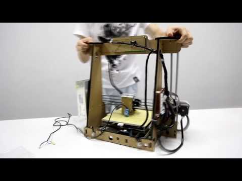
Order Shipment:
If your order is in stock and we process the charges to your credit card, it will ship within five business days from the date of your order. We will send you tracking information within 24 hours of your order leaving the warehouse to the e-mail address you provide when checking out. If you do not receive tracking information from us within six business days of your order feel free to follow up with us at [email protected]
Domestic Shipping:
We do not ship to P.O. Box.
International Shipping:
Please contact us for international shipping rates
Price Guarantee▼
We work very hard to ensure that we offer the absolute best prices online for all of our printers including Tevo 3D printer kits. If you find another online store that offers a lower price than us on Tevo 3D printers for sale, please let us know. We want you to feel confident when you buy a Tevo 3D printer or any of our other printers that you are getting the absolute best price for the product.
To request your partial refund simply e-mail us a link to the same product on our website, or on our competitors’ website and we will process the credit accordingly.
Our 100% Price Guarantee has some limitations:
- You must purchase the item from our website before requesting your Price Match Guarantee
- Promotions such as rebates and buy one, get one free offers are not eligible
- The item must be in stock on the competitors website
- The competitor must be an online store, they may not have a retail location
- The item must ship from the same country.
- The website cannot be a discounter or auction website (ie; eBay, overstock, etc..)
- The competitor must be an Authorized Retailer for the product in question
- The Price Match Guarantee includes the item price and the shipping charges, it excludes sales tax or any customs and duties
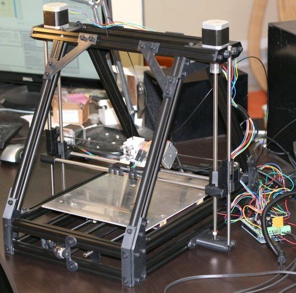
Assembling your ALUNAR 3D printer
The instructions for assembling your 3D printer are in video format.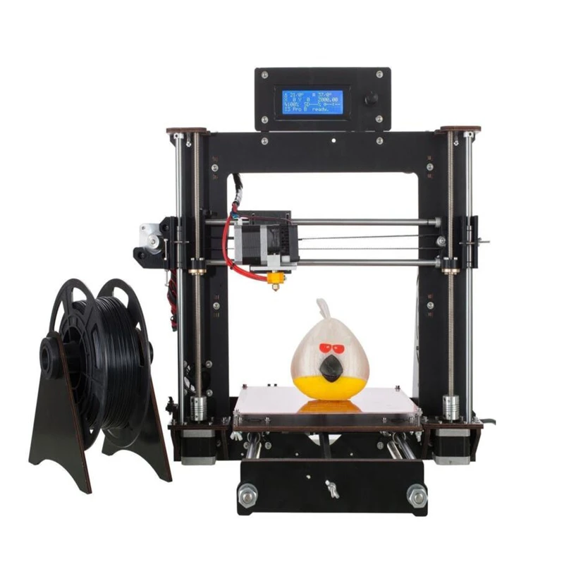 I’ve added notes here to help you interpret and check the video. Be sure to follow these directions very carefully. Also, be sure to watch each segment once before beginning that section of the assembly process. Lastly, you may find it useful to keep a larger picture of the printer open to compare to the video.
A. Assembling the X/Y frame (0:00-0:22)
- Before you assemble anything, watch the first 15 seconds of video. At 0:11 note that the aluminum extrusion for the frame you are making are all the same length, but two have a single hole and two have no hole. Be sure to line up your extrusion bars and find exactly those four (each is 37.5cm long). Also note that the bars with the holes go inside the other bars, and that the holes have room for an inset screw on one side but not the other (make sure they are rotated so that is on the same side for both bars). and follow this exactly.
- Be sure the aluminum extrusion bars are rotated correctly to match the video and find the corner pieces to attach the bars.
 Be sure to find an appropriate hex wrench so you can tighten them.
 - Check that your corners make right angles once assembled. Now turn your XY frame so that the inset sized holes in the extrusion crosspieces face up, and the small holes face down.
- Insert the right angle pieces and tighten the set screws that should already be placed in them.
- Attach the corner pieces to top of the XY frame. The corner pieces at 00:20 are laser cut acrylic. You’ll find them in a box of spare parts at the bottom of your printer box. You’ll need the T-nuts and the M4 8mm bolts for this, be sure to take the right length bolts from your 8mm & 12mm bolt bag. Also be sure to orient the bolts so that the bolt heads are inset and to orient the nuts so that the rough lines point in (toward the extrusion bar). Be sure to thoroughly tighten every bolt.
B. Assembly of Z Axis frame (0:22-1:03)
- Flip the XY frame over. Now the acrylic pieces and the inset holes are down.
 Then attach the two 44cm long Z extrusion pieces to the frame using two M5 25mm bolts as shown at 00:24 of the video.
 - Stabilize the Z axis as shown at 00:32, using the same M4 8mm bolts and T-nuts you used earlier along with the right angle supports. Not shown in the image, but critical is to make use of the washers here, otherwise your M4 8mm bolts might slip right through the holes in the right angle supports.
- 0:50 Attach the brackets for the motors using M4 8mm bolts and T-nuts. Position each one so that it is centered on the z-axis, and they rest against the floor when you place the x-y frame on the floor.
- Next attach the z-axis motors, using the M3 6mm screws. The right motors have identical motor shaft attachments, which resemble those in the video (don’t confuse them with the extruder motor or the x/y axis motors). Note that the cords attachments are not visible in the video because they are facing away from you (toward the shorter side of the x/y frame).
 Don’t overtighten the screws holding the motors as they will strip easily.
C. Assembly of print bed frame (1:03-1:18)
- Find the 41.5cm long extrusion. As can be seen at 1:04, this is placed across the x/y frame, and should be long enough to sit on top of it.
- Find the acrylic laser cut bed piece with the words X3 cut into it.
- Find the parts visible in the video at 1:06. These include four plastic pillars (found in the bag with the springs), four M5 nuts, four M5 35mm bolts, and 4 bearings. Assemble them as shown in the video. Make sure you tighten them properly (this will require a wrench to hold the bolts as you tighten the nuts).
- Slide the acrylic bed piece onto the crossbar, so that the bearings sit in the indentations in the extrusion. It should roll smoothly along the crossbar.
- Use the right angle supports (with T-nuts, M4 8mm bolts, and washers) to secure the crossbar to the XY frame. Make sure to center it.
 Important: If the printer front is facing you (i.e. the Z axis is more than halfway toward the back of the XY frame), the right angle supports go on the right side of the crossbar.
D. Attach the Y axis drive and timing belt (1:18-1:40)
- Add the y axis drive motor (1:19). The pointy extension of the laser cut acrylic should point away from the motor power supply. Use the M3 6mm bolts to attach the acrylic to the motor (note that the acrylic is non-symmetric, make sure the bolt heads are inset in it. Also, the set screws on the drive pulley on my motor were loose, so it came off. If that happens to you, just put it back on and tighten slightly (you may want to adjust the position of this later. Be sure one of the two set screws lines up with the flat side of the motor shaft when you do this).
- Add the y axis end stop (1:22). You should at this point compare all three end stops and pick the one with the shortest wire, as you will need a longer wire for the x axis end stop.
 Use the silver-colored M2 10mm bolts and M2 nuts found in the bag with the springs. Be sure to orient the end stop as shown in the video, on the same side of the acrylic as the motor, and with the metal switch opening up and out.
 - Attach the entire contraption to the crossbar using M4 8mm bolts and T-nuts. You will have to squeeze the bolts in between the wires coming off of the end-stop. Be gentle. Also make sure you are happy with where the wires going are as you tighten things down.
- Find the piece of acrylic shown in 1:28. Do not confuse it with the very similar piece in shape that has more than 3 holes in it. Attach it to the crossbar using M4 8mm bolts and T-nuts, so that the extra hole and rounded end stick out as shown at 1:28.
- Find the bearing, which is pre-assembled and in the bottom half of your printer box. You will need to unscrew the bolt, be careful to keep everything in the right order when you do so. Attach it as shown at 1:28/9.
- Find the timing belt. In the same bag you will find two black zip ties. The timing belt will run along the bottom of the crossbar, in the divet in its center. You’ll need to insert it between the crossbar and the xy frame. This is a good time to also adjust the position of the drive pully on the Y moter shaft, so that the timing belt lines up with the divet on that end. You will also need to insert the ends of the timing belt into the smily face cutouts on the print bed piece (with the X3 on it). With a little dugging you can slide it over until it lines up with the divet there too.
- Tighten and secure the timing belt. Making it tight enough is important for future functioning. Tightening can be done by moving the acrylic piece with the bearing attached (but you have to make sure there is room for it to move in the tighter direction. Assume your belt will loosen and leave your self some extra room for the future).
E. Extruder head carriage assembly (1:40-2:31)
- Find the triangular acrylic piece and motor mount shown at 1:42, along with 4 M4 12mm bolts and 4 M4 nuts.
 Assemble as shown, with the motor mount extending from the long side of the triangular acrylic piece.
 - Find the triangular acrylic piece (identical to step E1) and 3D printed plastic piece shown at 1:45, along with 2 M4 12mm bolts and 2 M4 nuts. Assemble as shown, noting the orientation and the location of the bolts in the middlemost holes of the acrylic. Do your best to make sure the top of 3D printed piece makes a right angle with the long end of the acrylic piece.
- Find the base for the z-axis threaded rod, and the bolts and nuts to secure it. They should all be in the same bag that the 3D printed piece was in. Assemble them as shown at 1:48.
- Attach the two pieces together as shown at 1:50. You will need six plastic pillars, and three bearings, M5 45mm bolts and M5 nuts. As usual, check orientation before you finish assembling and after.
- Repeat step 1, noting the 90 degree change in relative orientation of the acrylic piece and motor mount (see 1:57).
- Repeat step 2, noting the mirror image orientation (see 2:00).
- Repeat step 3 (2:02).
- Repeat step 4 (2:07). Pay attention to relative orientation.
- Place on the Z-axis frame as shown at 2:12. Pat yourself on the back :).
- You’re not done yet! Attach the extruder crossbar (40cm long) using M4 12mm bolts and T-nuts as shown at 2:22. It should be approximately centered.
- Gently screw in the z-axis threaded rods (2:26). I had to free mine from their saran wrap with a box cutter. Once they are positioned, loosen the thumb screws to move the shaft coupler, which is used to attach the threaded rods to the motors.
- Add the top bar. Use the two remaining M5 25mm bolts to attach it, and make sure you rotate it so that the bolt heads can be inset in the crossbar divet.
- Now pat yourself on the back again!
E. Attach the extruder head and X axis drive motor and timing belt (this is so exciting!). Video sequence 2:34-2:55.
- Attach the X drive motor (2:34) using four M3 6mm bolts. Pay attention to the orientation of the power plug, which should be down. As before, the drive pulley will be loose. Leave it loose.
- Slide the pre-assembled extruder head onto the extruder crossbar. Make sure the extruder head is pointing down (2:36)
- Attach the acrylic bearing to the acrylic bearing mount (2:41). This is the same style of pre-assembled bearing as we used for the Y timing belt (step D5).
- Attach the acrylic bearing mount to the crossbar (2:45) using two M4 8mm bolts and two T-nuts.
- Insert the timing belt (2:50), align it with the bearing and drive pulley, and pull it through the small holes in the extruder assembly shown at 2:52. Note the orientation of the timing belt, is with the teeth inwards, unlike what is shown in the video. Pull on the timing belt to tighten it and secure it with zip ties. Then make sure the drive pulley is correctly aligned, orient it so that one set screw is on the flat part of the drive shaft, and tighten.
F. Attach the extruder motor (2:56-3:03)
- Find the extruder assembly, which is in its own separate plastic bag and made of black metal. In the same bag, you will find a very short M5 (I think) bolt which requires a hex wrench to tighten. As shown in the picture below, it will fit into the larger extruder assembly piece, which has the bearing attached to it as well. Make sure the bolt in that piece is all the way in so it can sit in the inset hex-shaped area in the bolt (mine wasn’t). You will also find a spring, which goes over the bolt and sits in the other side of the extruder assembly. Watch the video a few times from 2:58-3:00 to see how this all fits together.
- Find the extruder motor. Make sure that the teeth are at the top of the motor shaft (you may need to loosen the set screws to do this). Note: The set screws on this motor are NOT metric. You will have to borrow a tool or buy a non-metric hex wrench set to adjust the position of these screws.

- Find an M3 22mm screw in the extruder assembly and use it to attach the motor to the motor mount (note: orientation of the assembly is important. See picture). Make sure the power plug faces to the back for the motor.
- Find the next M3 15mm bolt in the same bag and attach the rear right of motor
- Squeeze the extruder assembly together and attach the front left of motor with the final M3 22mm screw. Note that there is no place for a fourth screw.
- Find the small brass holder for the bowden cable. Insert the bowden cable into it, and screw it into the front of the extruder assembly.
G. Attach the end stops and print bed (3:04-3:18)
- Find the end stop with the longest cord and the acrylic mount shown at 3:04. Get two M2 10mm bolts and two M2 nuts and attach the end stop to the acrylic piece. Use two T-nuts and two M3 8mm bolts to attach the assembly to the X-axis crossbar (that the extruder is mounted on). At this point I discovered I was short a couple of T-nuts.
 We have extras ordered for your kits.
 - Find the last end stop (the z axis end stop) and acrylic mount shown at 3:10. Note that the orientation of the printer in the animation is backward — the back of the printer is facing you (you can see the power plug in the motor) and the front is away from you. This means that the end stop looks like it’s being mounted on the rear, right side of the printer but it actually belongs on the front, left side, as is visible at 3:15 in the video.
- Find the print bed, 4 M3 30mm bolts, 4 wing nuts, 4 regular nuts, and 4 springs. You also need 4 M3 nuts to secure the print bed above the spring. Attach the bolts to the metal bed with the regular nuts. Arrange as shown at 3:18. For orienting the print bed, the writing should go down and the power plug face to the back.
H. Assemble the electronics (3:21-4:00)
- Find the powerbox, electronics base (acrylic). Note the bright yellow sticker marking the switch between 110V and 220V.
 Before you do anything else, make sure the switch is all the way to the left!
 - Find the 3 M3 10mm bolts. Position the power box as shown at 3:21. Hold it in place as you turn the assembly over to find the bolt holes (Note: I was only able to match it up to 3 hols and bolts, but the video shows 4).
- Find four M3 20mm bolts and place them through the bolt holes shown at 3:26, putting plastic pillars on them once they are through the holes. This is a tricky maneuver as they want to fall out as you re-orient the electronics base.
- Find the long (5mmx21mm) green circuit board and place it with the USB port facing out (away from the power supply) in the position of the bright green rectangle in the video at 3:27. Secure with nuts as shown.
- Find an M3 20mm bolt and M3 nut and move the video to 3:29. The assembly order in the video is difficult. It is much easier to slide the bolt through the hole and place the nut on the bolt at the very top.
 Then place the plastic piece and adjust until the nut is in the inset shown in the video. Now tighten the bolt, and the plastic piece will be tightened into place.
 - Follow the same procedure to attach the piece shown in green at 3:34, using two M3 20mm bolts, and the piece in green shown at 3:38. Note the orientation and shape of the pieces, in particular, make sure that the USB port is accessible.
- Find the switch and plug shown at 3:42 and attach them to the corresponding acrylic piece with two M3 10mm bolts and M3 nuts.
I. Wiring your power supply (not in video).
- Wiring your power supply is a very important thing to get right!! Although it is not described in the video, your printer comes with a piece of paper that shows the wiring. With careful attention, wire the power supply to the switch as shown. Have the instructor check this if you have any concerns. It will wreck your electronics if you get it wrong.
- Also attach the free (both ends unattached) black and red wires as indicated to V- and V+, respectively.
- Now you can attach the back to the electronics base, as shown at 03:45.
- Turn over your piece of paper to see the wiring for the board.
- Attach the grey cable for the display to the board, and attach the display to the electronics base as shown at 03:52.
- Attach the wires labeled X, Y, Z1, Z2 and E to the correct locations on the board. Be sure to attach the correct side of the wires, and orient them the correct way. You can see by shape, as well as the color ordering of the wires in the picture and in your board. Run the wires along the top of the board and out the big hole near the power supply.
- Find the wires coming out of the extruder assembly. Push them through the same big hole as everything else, and wire them up. Plug in the fan, and thermistor wires as well.
- Plug the hot bed wires into the hot bed (these are difficult to get in, but the clasp should be on top). Push them through the same hole as everything else. Plug in the bed thermistor.
- Three sets of wires on your board are screwed in instead of plugged in.These are the extruder heater wires, the hot bed heater, and the power supply. Take very careful note of where each goes.Use the small yellow standard screwdriver to unscrew these screws. You have to raise the screws quite a lot to get the wires in properly. You’ve done it right if, once you tighten the screws down, the wires won’t come out. Be sure to put the black (V-) and red (V+) wires from the power supply in the proper order.
- Plug in the end stops. On the board, they have labels like ‘X-axial limit switch’ (X end stop). Also plug the motor wires into the motors, and you should be all wired up.
- Do not attach the cover to your wire box, as you probably made at least one mistake.
- Also don’t do this yet, but eventually: You can use the wire wrap to wrap your wires. The picture of the printer on the Alunar site shows very nicely which wires you want to wire wrap together.
J. Prepare your mac for connection to your board
- Install the Ch44OG Driver (Serial adapter) website https://blog.sengotta.net/signed-mac-os-driver-for-winchiphead-ch440-serial-bridge/ and instructions if that doesn’t work after restart (for later versions of osx): https://tzapu.com/making-ch440-ch441-serial-adapters-work-under-el-capitan-os-x/
- Download Repetier Host
- The repetier software download website : http://www.repetier.com/download-now/
- In order to get your printer running, you will need to change a few settings. Use Command or Control P to open the printer settings. In the connection tab, set the Port to the serial port your printer will be using, set the Baud Rate to 115200, set the Transfer Protocol to Force ACII Protocol, and set the Receive Cache Size to 127. Also make sure that Use Ping-Pong Communication and Firmware sends OK after error are checked. Then go to the dimensions tab and fill in the correct dimensions for your printer (220 x 220 x 220 should work).
- Install the FTDI usb driver. Download website: http://www.ftdichip.com/Drivers/VCP.htm
- Begin testing. When everything works, then cover it :).
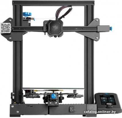
Firmware Alunar m508 - 3D printers
marlin prusa-i3 firmware alunar-m508
I have an Alunar M508 machine on which I am trying to install new firmware. The firmware that was loaded on the machine was not very good. The x-axis was mirrored and the starting point was far away. I've been looking for Marlin to put it on the machine, but I don't have any experience with what to edit in the code to get it to work on that machine.
Does anyone have experience with this machine? Downloading a new firmware that works or editing the code to make it work on this machine. I appreciate any help!
Here is a link to the firmware I am currently using. I'm on macOS Sierra 10.12.5 using the Arduino 1.6.8 development environment. @Donnie Plumly
Firmware will not improve your print quality. well, to some extent it can be, but for the most part it won't happen.
Requires fine tuning that can be set for MY printer, but you may need to change the values. Not to mention the physical setup I did with my printer. Software is not where you should initially look for print quality improvements.
Some examples:
I printed the anti-vibration caps for the Z-axis rods. Which improved the printing a lot for me. As the print got taller, the quality deteriorated.
I printed Z-stop improvements so I can fine-tune the Z-stop.
I printed X & Y belt tensioners. Loose belts result in skipped steps resulting in poor print quality.
, @ Ryan Conrad
▲ 1
The Alunar firmware you linked is a fork from the main Marlin firmware. If the Y table direction is reversed, usually the stepper switch is not positioned correctly (mirrored), this is often seen with the Anet A8 printer, which is very similar to your printer.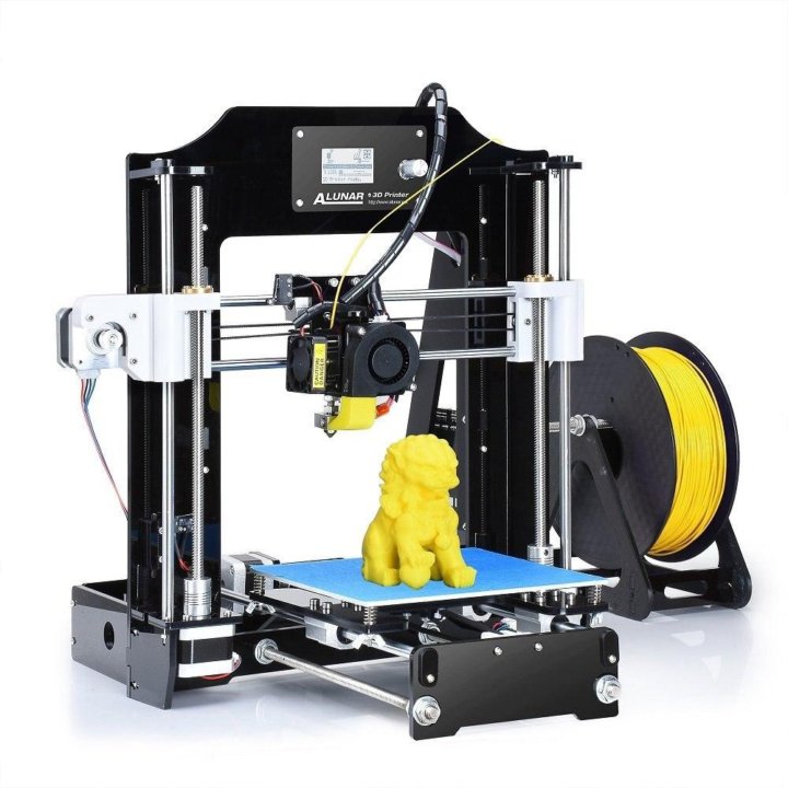 In your case the X direction is not correct, usually due to the wiring of the stepper, turning the connector 180 degrees should help (hardware solution). As a software solution, changing direction is a breeze in Marlin-based firmware; you just want to change the direction of the step; the following section in the config.h file does this for you:
// Invert the stride direction. Change (or reverse the motor connector) if the axle goes the wrong way. #define INVERT_X_DIR false #define INVERT_Y_DIR false #define INVERT_Z_DIR true
Just change the value of INVERT_X_DIR to true .
If your home position still doesn't work for you, you should look into this section of the same config file:
// Travel limits (mm) after hovering corresponding to end stop positions. #define X_MIN_POS -33 #define Y_MIN_POS -10 #define Z_MIN_POS 0 #define X_MAX_POS X_BED_SIZE #define Y_MAX_POS Y_BED_SIZE #define Z_MAX_POS 240
Change MIN_POS positions so that they start at the corner of the table.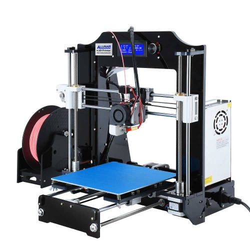 A more detailed guide to desktop center calibration can be found here.
Please don't print anti wobble caps for z axis bars (as mentioned in another answer), they don't reduce wobble, in fact they cause problems. What happens if you limit the top is that you end up with a statically indeterminate construct; forces and movements are unpredictable! The best solutions to eliminate Z-wobbles are lifting devices that separate the X/Y movement from the threaded rod (threaded rod eccentricity) from the Z movement.
, @ 0scar
ESA demonstrates its 3D-printed space base project that in the not too distant future, the first inhabited base will still appear on the surface of another planet or cosmic body. And what such a base might look like is demonstrated by representatives of the European Space Agency (ESA), presenting a project for an inflatable space base, the outer shell of which is built from local materials and which can provide all the conditions necessary for a fairly comfortable living and working of four people.

The design of the lunar base was developed by the ESA specialists together with the employees of the architectural firm Foster + Partners. And, according to the available information, the implementation of such a project will become possible in the next 40 years, when some existing technologies will be finalized and a number of new technologies necessary for this will be developed.
The main task that the specialists tried to solve when creating the project of the base is that at least 90 percent of the materials for its construction should be local materials. And only 10 percent, falling on the share of construction robots, inflatable modules, light power metal structures, airlocks and some other devices and components, must be delivered from Earth.
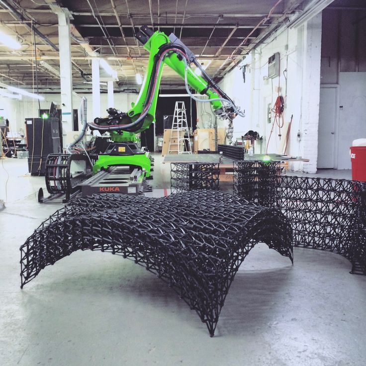
The construction of the base will be carried out by robots in automatic mode. First, inflatable structures will be inflated with air and airlock modules will be installed. After that, 3D printer robots will begin to work, using powdered lunar rock, will begin the construction of domes with a light cellular structure that will protect the inhabitants of the base from small meteorites, cosmic radiation and significant temperature fluctuations.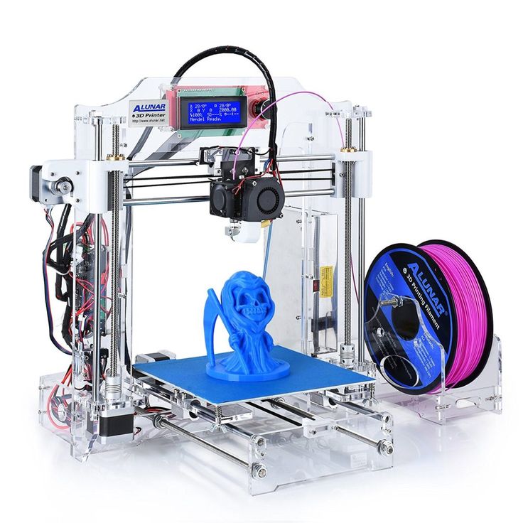
"3D construction printing technology gives us all the capabilities we need to build extraterrestrial bases," says Scott Hovland, head of one of ESA's research departments. that will need to be delivered to the Moon from the Earth.
In order to minimize the amount of building mix components that need to be delivered to the Moon from Earth, the space base shell will have a honeycomb structure with cavities filled with lighter, less dense regolith powder. At the same time, the structure of the structure is designed in such a way that the strength of the base dome does not suffer in any way due to the reduction in its weight. “We already have quite a wealth of experience in the construction of premises designed to operate in extreme climatic conditions on Earth,” says Xavier De Kestelier, one of the leaders of Foster + Partners, “And all this experience can be quite successfully used in the construction of space bases.
"We have already tested it using a special material that most closely matches the composition of lunar rock material.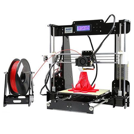 Some magnesium oxide is added to the ground powder, after which the printer prints the job layer by layer," says Enrico Dini, Founder and the head of Monolite, a space 3D printing technology company, "After the layer dries, we treat the resulting surface with a solution of certain salts, which act as a kind of" fixer ", turning the building material into a very hard stone."
The design of a prototype space 3D printer allows printing at a speed of about two meters of wall per hour. But the development of another design of the same printer is already underway, which will be able to provide a productivity of 3.5 meters per hour and which should be enough to erect all the structures of the space base in a week of work.
Keywords:
Space, moon, Earth, Planet, Base, Construction, 3D, Printing, Robot, Material, ESA
Primary
Other news on the topic: